

Инструкция на Контроллеры серии pCO...
Руководство по эксплуатации модулей расширения pCO: pCOB, pCO2, pCO1 и pCOC I/O
Смотрите также: Программируемые электронные контроллеры pCO1 →
Загружаем документ…
Текст инструкции
-
There can be a maximum number of 5 expansion boards for each pCO* board
The following programmable controllers can be used as I/O expansions, that is, “Slaves”: • pCOB standard (any model); • pCOB expansion (code PCOBCP0A21); • pCO2 (any model): only if the pCO2 master was manufactured after December 2001; • pCO1/pCOC(any model): only if the pCO2 master was manufactured…
-
Even if not economically convenient, a pCO2 LARGE can be used at the same time as both an
expansion for another pCO2 Master and a master for other expansions. Features of the application SW on the pCO² Master The following features are required for the software on the Master controller: • Read/write the inputs/outputs on the expansions using the atoms Ain/ Din/ Aout/ Dout. The value of…
-
• o by assigning IDENT a constant value (in this way, however, each expansion requires different software); o by reading the value of the dipswitches using the system variable NET_ADDRESS and assigning this value to IDENT. Note: the address set using the dipswitches for the expansions is not a pLAN…
-
Aout
Aout Aout Aout Aout Aout X11 X12 X13 X14 X15 ……. ……. X50 Riinnm, Riout Riinnm, Riout Riinnm, Riout Riinnm, Riout Riinnm, Riout ……. ……. Riinnm, Riout …… …… 40 Table 1. Coding of the inputs and outputs. (*): “X”= expansion number, from 1 to 5. Example: to control relay number 2 on expansion number 5…
-
Examples
Analogue input expansion The figure shows an example of the software to be configured on the Master and on the Expansion: MASTER EXPANSION Master Use the Ain atom to read the value sent by the expansion, setting the value ChAinMaster = X * 100 + ChAinExpansion for the Ch pin, where X = number of the…
-
Analogue output expansion
The figure shows an example of the software to be configured on the Master and on the Expansion: MASTER EXPANSION Master Use the Aout atom to send the value to the expansion, setting the Ch pin to the value ChAoutMaster = X * 100 + ChAoutExpansion, where X = number of the expansion that the analogue…
-
Configuration variables
The figure shows an example of the software to be configured on the Master and on the Expansion: MASTER EXPANSION Master Use the Aout atom to send the value to the expansion, setting the Ch pin to the value ChAoutMaster = X * 100 + Y, where X = number of the expansion that the configuration variable…
-
Introduction The pCOE expansions do not require software onboard, as they communicate according to a predefined table. tLAN expansions The tLAN expansions can be connected directly to a pCOxs or pCO1 tLAN using the serial connection card (code PCO100TLN0). A maximum of 5 expansions can be connected.…
-
How to read a variable from the expansion
The digital/analogue variables are read in the same way from a RS485 and tLAN expansion. To read a variable, simply use the AIN atom (in the case of analogue or integer variables) and the DIN atom (in the case of digital variables), as for the expansions using pCOX controllers. The output value Val…
-
Integer configuration variables
Le variabili di configurazione permettono di impostare dei parametri all’interno della espansione come il tipo di sonda analogica utilizzata (NTC, 0-5 V, 4-20 mA). Le variabili di configurazione possono non essere usate dall’applicativo; in questo caso l’espansione pCOe utilizza i valori di default…
-
Type of analogue inputs
This selection is similar to the “Ain_pco2” atom when configuring an analogue probe for a pCO. The possible values are: 0 NTC probe 2 0-1V probe 4 0-20mA probe 6 0-5V probe Pattern dell'uscita analogica e delle 4 uscite digitali Permette di stabilire lo stato delle uscite in assenza di comunicazione…
-
Digital variables
-
Using the disabling patterns
Le matrici di inibizione permettono di forzare al valore “0” una o più uscite digitali. Gli effetti delle due matrici di inibizione si sovrappongono. Se, a matrici attive, subentra l'allarme di OFF-LINE, l'eventuale pattern di allarme delle uscite digitali è prioritario rispetto alle matrici di…
-
Pattern according to the analogue inputs
This function is used to set one or more digital outputs to “0” according to the status of the predefined analogue input on the expansion. 1) First of all “Select the analogue input for the activation of the pattern” (integer). The table below shows the possible values for this variable: Set probe 1…
-
Significato dei LED di segnalazione
I significati dei LED esposti nella tabella seguente sono LED rosso - LED giallo acceso acceso - lampeggiante - - - LED verde significato acceso comunicazione attiva. errore sonde. errore di "I/O mismatch" da più di 10 sec., causato dalle matrici di inibizione. mancanza di comunicazione da più di 30…
Схемы, таблицы и рисунки — в просмотре документа выше. Клик по номеру страницы открывает её в просмотре.
Новое в каталогах
-
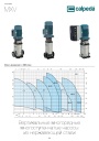
Каталог вертикальных многоступенчатых насосов Calpeda серий MXV, MXVL, MXV EI 2026. pdf, 7.05 Mb
Модели: MXV 25, 32, 40, 50, 65, 80, 100, MXVL 65, 80, MXV EI. Каталог серии: область применения, конструкция и материалы, рабочие характеристики и кривые, габаритные размеры и масса. -

Каталог осевых вентиляторов Shuft серии AXW. pdf, 4.05 Mb
Модели: AXW 4E–8DY с типоразмерами 200–910 в исполнениях S-G, S-T, B-T, B-P. Технический каталог модельного ряда: расшифровка обозначения, характеристики, схемы подключения, аэродинамические графики и габаритные чертежи. -
Каталог продукции Пульсар 2026 - Дренажные насосы. pdf, 3.91 Mb
Каталог продукции Пульсар 2026 - Дренажные насосы
Новое в инструкциях
-

Водонагреватели косвенного нагрева Immergas серии Standart UBS . pdf, 676.07 Kb
Водонагреватели косвенного нагрева Immergas серии Standart UBS150/ Standart UBS 200/ Standart UBS 300 вертикальные из углеродистой стали толщиной 2мм с эмалевым покрытием емкостью 150/200/300 литров. Руководство по эксплуатации. -

Топочный автомат горения ОВЕН МГ1. pdf, 10.23 Mb
Руководство по эксплуатации топочного автомата горения МГ1 для автоматизации розжига и контроля пламени промышленных газовых надувных и атмосферных горелок (1- и 2-ступенчатых): технические характеристики, монтаж и схемы подключения, подключение датчика пламени и OwenCloud, принцип работы и диаграммы, режимы работы, настройка в Owen Configurator, защиты, список аварий, карта регистров сетевого интерфейса, выносная панель МГ1-ВП, техническое обслуживание. -

Электрические накопительные водонагреватели STOUT серии SEW . pdf, 3.22 Mb
Электрические настенные накопительные водонагреватели STOUT серии SEW-030L-01; SEW-050L-01; SEW-080L-01; SEW-100L-01 объемом 30-100 литров. Технический паспорт.