

Инструкция на Полупромышленные кондиционеры Digital Inverter
Полупромышленные кондиционеры Digital Inverter и Super Digital Inverter 3 серия. Инструкция по обслуживанию и ремонту.
Смотрите также: Инструкция по обслуживанию и ремонту →
Загружаем документ…
Текст инструкции
-
FILE NO. A06-010
-
SAFETY CAUTION
The important contents concerned to the safety are described on the product itself and on this Service Manual. Please read this Service Manual after understanding the described items thoroughly in the following contents (Indications/Illustrated marks), and keep them. [Explanation of indications]…
-
WARNING
Check earth wires. Before troubleshooting or repair work, check the earth wire is connected to the earth terminals of the main unit, otherwise an electric shock is caused when a leak occurs. If the earth wire is not correctly connected, contact an electric engineer for rework. Do not modify the…
-
WARNING
Insulator check Ventilation After the work has finished, be sure to use an insulation tester set (500V mugger) to Ω or more between the charge section and the non-charge check the resistance is 2MΩ metal section (Earth position). If the resistance value is low, a disaster such as a leak or electric…
-
This air conditioner adopts a new HFC type refrigerant (R410A) which does not deplete the ozone layer. 1. Safety Caution Concerned to New Refrigerant The pressure of R410A is high 1.6 times of that of the former refrigerant (R22). Accompanied with change of refrigerant, the refrigerating oil has…
-
4. Tools
1. Required Tools for R410A Mixing of different types of oil may cause a trouble such as generation of sludge, clogging of capillary, etc. Accordingly, the tools to be used are classified into the following three types. 1) Tools exclusive for R410A (Those which cannot be used for conventional…
-
1. SPECIFICATIONS
1-1. Indoor Unit 1-1-1. 4-Way Air Discharge Cassette Type <Digital Inverter> Indoor unit RAV- SM563UT-E SM803UT-E SM1103UT-E SM1403UT-E Outdoor unit RAV- SM563AT-E SM803AT-E SM1103AT-E SM1403AT-E Cooling capacity (kW) 5.3 6.7 10.0 12.1 Heating capacity (kW) 5.6 8.0 11.2 14.0 Model Power supply 1…
-
Indoor unit
-
1-1-2. Concealed Duct Type
<Digital Inverter> Indoor unit RAV- SM562BT-E SM802BT-E SM1102BT-E SM1402BT-E Outdoor unit RAV- SM563AT-E SM803AT-E SM1103AT-E SM1403AT-E Cooling capacity (kW) 5.0 7.1 10.0 12.5 Heating capacity (kW) 5.6 8.0 11.2 14.0 Model Power supply 1 phase 230V (220 – 240V) 50Hz Running current (A) 8.52 – 7.81…
-
Indoor unit
RAV- SM562BT-E SM802BT-E SM1102BT-E SM1402BT-E Outdoor unit RAV- SP562AT-E SP802AT-E SP1102AT-E SP1402AT-E Cooling capacity (kW) 5.0 7.1 10.0 12.5 Heating capacity (kW) 5.6 8.0 11.2 14.0 Model Power supply 1 phase 230V (220 – 240V) 50Hz Running current (A) 6.51 – 5.97 9.74 – 8.93 11.72 – 10.74 18.09…
-
1-1-3. Under Ceiling Type
<Digital Inverter> Indoor unit RAV- SM562CT-E SM802CT-E SM1102CT-E SM1402CT-E Outdoor unit RAV- SM563AT-E SM803AT-E SM1103AT-E SM1403AT-E Cooling capacity (kW) 5.0 7.0 10.0 12.3 Heating capacity (kW) 5.6 8.0 11.2 14.0 Model Power supply 1 phase 230V (220 – 240V) 50Hz Running current (A) 8.71 – 7.98…
-
Indoor unit
RAV- SM562CT-E SM802CT-E SM1102CT-E SM1402CT-E Outdoor unit RAV- SP562AT-E SP802AT-E SP1102AT-E SP1402AT-E Cooling capacity (kW) 5.0 7.1 10.0 12.5 Heating capacity (kW) 5.6 8.0 11.2 14.0 Model Power supply 1 phase 230V (220 – 240V) 50Hz Running current (A) 6.61 – 6.06 9.74 – 8.93 11.24 – 10.31 18.09…
-
1-1-4. Twin Type
-
4-Way Air Cassette
-
1-2. Outdoor Unit
<Digital Inverter> Model name RAV- SM563AT-E Type Motor (kW) Refrigerant charged (kg) 1.1 1.6 2.5 3.0 1.0 1.7 2.8 2.8 Refrigerant control Pulse motor valve Standard length (m) 7.5 7.5 7.5 7.5 Min. length (m) 5.0 5.0 5.0 5.0 Max. total length (m) 20g/m (21m to 30m) 40g/m (21m to 30m) 40g/m (31m to…
-
Model name
-
1-3. Operation Characteristic Curve
-
• Operation characteristic curve <Super Digital Inverter>
-
• Capacity variation ratio according to temperature
-
2. AIR DUCTING WORK
-
3. CONSTRUCTION VIEWS (EXTERNAL VIEWS)
3-1. Indoor Unit 3-1-1. 4-Way Air Discharge Cassette Type RAV-SM563UT-E, RAV-SM803UT-E 200 860 to 910 Recommended external size 860 to 910 Recommended external size Check port ( 450) 200 ¨ Check port ( 450) ¨ Standing 850 or less 130 105 Standing 640 or less Surface under ceiling Surface under…
-
860 to 910 Recommended external size 860 to 910 Recommended external size 200 Check port ( 450) 200 ¨ Check port ( 450) ¨ C D SM1103 Ø9.5 Ø15.9 A 183 319 SM1403 Ø9.5 Ø15.9 183 319 SP1102 Ø9.5 Ø15.9 183 319 B 105 130 Ceiling bottom surface Electric parts box Surface under ceiling Refrigerant pipe…
-
3-1-2. Concealed Duct Type
RAV-SM562BT-E, RAV-SM802BT-E, RAV-SM1102BT-E, RAV-SM1402BT-E Hanging bolt pitch B 41 Main unit dimension A 50 638 H 498 60 to Suction port flange (Separate sold) Refrigerant pipe connecting port (Liquid side ØG) 9 6-Ø4 Tapping screw undersized hole Ø160 393 41 Knock-out hole Ø125 (Air take-in port)…
-
3-1-3. Under Ceiling Type
RAV-SM562CT-E, RAV-SM802CT-E, RAV-SM1102CT-E, RAV-SM1402CT-E Upper pipe draw-out port (Knockout hole) 210 Power supply cable take-in port (Knockout) Pipe draw-out port (Knockout hole) Drain port VP20 (Inner dia. Ø26, hose attached) B (Hanging position) Refrigerant pipe (Gas side ØD) Drain pipe…
-
3-2. Outdoor Unit
RAV-SM563AT-E, RAV-SM803AT-E Drain hole (2-Ø20 × 88 long hole) Drain hole (Ø25) 600 90 A legs 54 306 Ø6 hole pitch 290 Connecting pipe port Gas flare side RAV-SM563AT-E: Ø12.7 RAV-SM803AT-E: Ø15.9 30 ( ) Connecting pipe port Liquid flare side RAV-SM563AT-E: Ø6.4 RAV-SM803AT-E: Ø9.5 ) ( 8-Ø6 hole…
-
Knockout
(For draining) Drain hole (Ø20 × 88 Burring hole) Drain hole (Ø25 Burring hole) Suction Part B 17.5 Suction port 21 43 (Long hole pitch for anchor bolt) 40 70 Details of B part Knockout (For draining) 43 Part A 17.5 Discharge port Details of A part 95 900 Installation bolt hole (Ø12 × 17 U-shape…
-
21 Suction port Knockout (Drain) Drain hole (Ø20 x 88) Suction Knockout (Drain) port 40 Discharge port B legs A legs 43 17.5 21 26 Drain hole (Ø25) 108 320 1340 Refrigerant pipe connecting port (Ø15.9 flare at gas side) z Discharge guide mounting port (8-Ø3 embossing) Refrigerant pipe connecting…
-
4. SYSTEMATIC REFRIGERATING CYCLE DIAGRAM
4-1. Indoor Unit/Outdoor Unit RAV-SM563UT-E, RAV-SM562BT-E, RAV-SM562CT-E / RAV-SM563AT-E Outer diameter of refrigerant pipe Gas side ØA Liquid side ØB 12.7mm 6.4mm Indoor unit TCJ sensor Air heat exchanger Height difference (m) TC sensor Outdoor unit at lower side 30 30 Refrigerant pipe at gas side…
-
Outer diameter of refrigerant pipe Gas side ØA Liquid side ØB 15.9mm 9.5mm Indoor unit TCJ sensor Air heat exchanger Height difference (m) Outdoor unit at lower side 30 30 Refrigerant pipe at gas side Ø15.9 Height difference Outdoor unit at upper side TC sensor TS sensor Section shape of heat…
-
Outer diameter of refrigerant pipe Gas side ØA Liquid side ØB 15.9mm 9.5mm Indoor unit Distributor (Strainer incorporated) TCJ sensor Strainer Height difference (m) Air heat exchanger Outdoor unit at lower side 30 30 TC sensor Refrigerant pipe at gas side Ø15.9 Height difference Outdoor unit at…
-
Outer diameter of refrigerant pipe Gas side ØA Liquid side ØB 15.9mm 9.5mm Indoor unit Distributor (Strainer incorporated) TCJ sensor Strainer Height difference (m) Air heat exchanger Outdoor unit at lower side 30 30 TC sensor Refrigerant pipe at gas side Ø15.9 Height difference Outdoor unit at…
-
Outer diameter of refrigerant pipe Gas side ØA Liquid side ØB 12.7mm 6.4mm Indoor unit TCJ sensor Air heat exchanger Height difference (m) Outdoor unit at upper side Outdoor unit at lower side 30 15 TC sensor * The refrigerating cycle of the indoor units differs according to the models to be…
-
Outer diameter of refrigerant pipe Gas side ØA Liquid side ØB 15.9mm 9.5mm Indoor unit TCJ sensor Air heat exchanger Height difference (m) Outdoor unit at upper side Outdoor unit at lower side 30 15 TC sensor * The refrigerating cycle of the indoor units differs according to the models to be…
-
Outer diameter of refrigerant pipe Gas side ØA Liquid side ØB 15.9mm 9.5mm Indoor unit Distributor (Strainer incorporated) TCJ sensor Strainer Height difference (m) Air heat exchanger Outdoor unit at upper side Outdoor unit at lower side 30 15 TC sensor * The refrigerating cycle of the indoor units…
-
Outer diameter of refrigerant pipe Gas side ØA Liquid side ØB 15.9mm 9.5mm Indoor unit Distributor (Strainer incorporated) TCJ sensor Strainer Height difference (m) Air heat exchanger Outdoor unit at upper side Outdoor unit at lower side 30 15 TC sensor * The refrigerating cycle of the indoor units…
-
5. WIRING DIAGRAM
5-1. Indoor Unit 5-1-1. 4-Way Air Discharge Cassette Type RAV-SM563UT-E, RAV-SM803UT-E, RAV-SM1103UT-E, RAV-SM1403UT-E, RAV-SP1102UT-E TA FS CN34 (RED) LM1 TC Connection interface (option) CN104 (YEL) CN102 (RED) CN101 (BLK) CN80 (GRN) CN73 (RED) CN70 (WHI) (EXCT) MCC-1402 CN33 (WHI) LM2 TCJ Control…
-
5-1-2. Concealed Duct Type
RAV-SM562BT-E, RAV-SM802BT-E, RAV-SM1102BT-E, RAV-SM1402BT-E TA FS TCJ TC CN104 (YEL) CN102 (RED) CN101 (BLK) CN80 (GRN) CN73 (RED) CN70 (WHI) CN34 (RED) (EXCT) MCC-1402 Control P.C. Board for Indoor Unit CN33 (WHI) DC20V DC15V DC12V DC7V FM P.C. 3 3 Board CN60 3 (WHI) 2 1 + – ~ ~ RY 303 CN68 (BLU)…
-
5-1-3. Under Ceiling Type
RAV-SM562CT-E, RAV-SM802CT-E, RAV-SM1102CT-E, RAV-SM1402CT-E TA FS TC TCJ CN104 (YEL) CN102 (RED) CN101 (BLK) CN80 (GRN) CN73 (RED) CN70 (WHI) CN34 (RED) (EXCT) MCC-1402 Control P.C. Board for Indoor Unit CN33 (WHI) LM DC20V DC15V DC12V DC7V FM P.C. 3 3 Board CN60 3 (WHI) CN40 1 2 (BLU) U3 U4…
-
CN300
P04 P05 P06 Q200~205 IGBT R221 YEL P24 P23 R220 R320 YEL R219 R319 BRN P22 P21 YEL P20 P35 Fan motor CN700 F03 Fuse T3.15A AC250V C13 DB01 CN603 CN602 Power relay DB02 Relay P08 Color Identification BLK : BLACK BLU : BLUE RED : RED GRY : GRAY PNK : PINK WHI : WHITE BRN : BROWN ORN : ORANGE YEL…
-
P24
RED P21 BRN P29 ORN BLU P18 P19 P20 YEL ~ P17 ~ F01 Fuse T25A, 250V~ IGBT MODULE RY01 F02 Fuse T25A, 250V~ Power factor control P.C. board (MCC-1438) 5 CN13 5 RED 1 2 CN05 WHI CN06 CN04 RED WHI 1 3 CN600 1 2 BLK BLK ORN PNK RED BLU WHI BLK YEL BLU WHI CN02 5 CN01 5 RED 1 CN04 1 2 WHI CN800 CN03 RED…
-
P24
RED P21 BRN P29 ORN P18 P17 P20 IGBT MODULE RED F02 Fuse T25A, 250V~ P.C. board (MCC-1438) 5 CN13 5 RED 1 2 CN05 WHI CN06 CN04 RED WHI BLK ORN PNK RED BLU WHI BLK YEL BLU WHI Power factor control 5 CN01 5 RED 1 CN04 1 2 WHI CN800 CN03 RED WHI CN03 CN20 RED CN21 WHI CN22 BLK W V U L N Power supply…
-
P18
P17 P20 P19 IGBT MODULE RED P.C. board (MCC-1438) 5 CN13 5 RED 1 2 CN05 WHI CN06 CN04 RED WHI 1 3 CN600 1 2 BLK RED BLK ORN PNK RED BLU WHI BLK YEL BLU WHI Power factor control TH CN01 5 RED 1 CN04 1 2 WHI CN800 CN03 RED WHI CN09 RED CN10 WHI CN11 BLK W V U Power supply 220-240V~ 50Hz PMV FM FM…
-
6. SPECIFICATIONS OF ELECTRICAL PARTS
-
6-1-2. Concealed Duct Type
-
6-2. Outdoor Unit
-
6-3. Accessory Separate Soldparts
-
7. REFRIGERANT R410A
This air conditioner adopts the new refrigerant HFC (R410A) which does not damage the ozone layer. The working pressure of the new refrigerant R410A is 1.6 times higher than conventional refrigerant (R22). The refrigerating oil is also changed in accordance with change of refrigerant, so be careful…
-
Table 7-2-1 Thicknesses of annealed copper pipes
Thickness (mm) Nominal diameter Outer diameter (mm) R410A R22 1/4 6.4 0.80 0.80 3/8 9.5 0.80 0.80 1/2 12.7 0.80 0.80 5/8 15.9 1.00 1.00 1. Joints For copper pipes, flare joints or socket joints are used. Prior to use, be sure to remove all contaminants. a) Flare Joints Flare joints used to connect…
-
c) Insertion of Flare Nut
d) Flare Processing Make certain that a clamp bar and copper pipe have been cleaned. By means of the clamp bar, perform the flare processing correctly. Use either a flare tool for R410A or conventional flare tool. Flare processing dimensions differ according to the type of flare tool. When using a…
-
Table 7-2-6 Flare and flare nut dimensions for R22
Nominal diameter Outer diameter (mm) Thickness (mm) 1/4 6.4 3/8 Dimension (mm) Flare nut width (mm) A B C D 0.8 9.0 9.2 6.5 13 17 9.5 0.8 13.0 13.5 9.7 20 22 1/2 12.7 0.8 16.2 16.0 12.9 20 24 5/8 15.9 1.0 19.4 19.0 16.0 23 27 3/4 19.0 1.0 23.3 24.0 19.2 34 36 6˚ to 4 45˚ B A C 43˚ D to 4 5˚ Fig.…
-
7-3. Tools
7-3-1. Required Tools Refer to the “4. Tools” (Page 8) 7-4. Recharging of Refrigerant When it is necessary to recharge refrigerant, charge the specified amount of new refrigerant according to the following steps. Recover the refrigerant, and check no refrigerant remains in the equipment. When the…
-
1) Be sure to make setting so that liquid can be charged
2) When using a cylinder equipped with a siphon, liquid can be charged without turning it upside down. It is necessary for charging refrigerant under condition of liquid because R410A is mixed type of refrigerant. Accordingly, when charging refrigerant from the refrigerant cylinder to the equipment…
-
2. Characteristics required for flux
7-5-3. Brazing • Activated temperature of flux coincides with the brazing temperature. • Due to a wide effective temperature range, flux is hard to carbonize. • It is easy to remove slag after brazing. • The corrosive action to the treated metal and brazing filler is minimum. • It excels in coating…
-
Instruction of Works: The existing R22 and R407C piping can be reused for our digital inverter R410A products installations. NOTE) Confirmation of existence of scratch or dent of the former pipes to be applied and also confirmation of reliability of the pipe strength are conventionally referred to…
-
7-6-5. Final Installation Checks
Is there no scratch or dent on the existing pipes? Existing pipe: NO * Use a new pipes. NO Is it possible to operate the existing air conditioner? YES * After the existing air conditioner operated in cooling mode for approx. 30 minutes or longer*, recover the refrigerant. * For cooling the pipes and…
-
• When recovering refrigerant in case of reinstallation of the indoor or outdoor unit, etc., use the refrigerant recovery switch on the terminal block of the outdoor unit. Work procedure Refrigerant recovery switch ON 1. Turn on the power supply. 2. Using the remote controller, set FAN operation to…
-
8. CONTROL BLOCK DIAGRAM
8-1. Indoor Control Circuit Weekly timer Main (Sub) master remote controller *1 Connection Interface is attached to master unit. (In case of group control operation) Display LCD *2 Weekly timer is not connectable to the sub remote controller. Display LED Function setup LCD driver Key switch Display…
-
8-2. Control Specifications
No. Item Outline of specifications 1 When power supply is reset 1) Distinction of outdoor units When the power supply is reset, the outdoors are distinguished, and control is exchanged according to the distinguished result. 2) Setting of speed of the indoor fan/setting whether to adjust air…
-
Room temperature control Remarks Outline of specifications 1) Adjustment range Remote controller setup temperature (°C) COOL/ DRY Heating operation Auto operation Wired type 18 to 29 18 to 29 18 to 29 Wireless type* 18 to 30 16 to 30 17 to 27 * : Only for 4-way air discharge cassette type and Under…
-
Outline of specifications Item Air speed <HEAT> selection (Continued) Remarks Ta (˚C) L(L) L(H) H(H) (-0.5) –1.0 (0) Tsh (+0.5) +1.0 (+1.0) +2.0 (+1.5) +3.0 E H (HH) D HH (HH) C B (+2.0) +4.0 A Value in the parentheses indicates one when thermostat of the remote controller works. Value without…
-
Freeze preventive control (Low temperature release) Outline of specifications Remarks 1) The cooling operation (including Dry operation) is Tcj : Indoor heat experformed as follows based on the detected temperachanger sensor ture of Tc sensor or Tcj sensor. temperature When [J] zone is detected for…
-
Drain pump control Outline of specifications 1) In cooling operation (including Dry operation), the drain pump is usually operated. 2) If the float switch operates while drain pump operates, the compressor stops, the drain pump continues the operation, and a check code is output. 3) If the float…
-
12 Frequency fixed
operation (Test run) Outline of specifications Remarks <In case of wired remote controller> 1. When pushing [CHECK] button for 4 seconds or more, [TEST] is displayed on the display screen and the mode enters in Test run mode. 2. Push [ON/OFF] button. 3. Using [MODE] button, change the mode from…
-
Outline of specifications
14 Central control mode selection 1) Setting at the central controller side enables to select the contents which can be operated on the remote controller at indoor unit side. 2) RBC-AMT31E [Last push priority] : The operation contents can be selected from both remote controller and central…
-
Max. frequency cut control Outline of specifications Remarks 1) This control is operated by selecting [AUTO] operation mode. 2) COOL operation mode: the frequency is controlled according to the following figure if To < 28°C. Ta(˚C) Normal control +4 +3 Max. frequency is restricted to approximately…
-
Connection interface
DC fan output Indoor/Outdoor inter-unit cable Optional power supply – 70 – Remote controller power supply LED DC fan return *1 Drain pump output Float SW Fan output HA (T10) TA sensor Optional output Louver (Used only for 4-way Air Discharge Cassette Type,Under ceiling type) TCJ sensor EXCT DISP…
-
9. CIRCUIT CONFIGURATION AND CONTROL SPECIFICATIONS
9-1. Indoor Control Circuit 9-1-1. Indoor P.C. Board Optional Connector Specifications Function Option output Outside error input Filter option error Connector No. Pin No. CN60 1 DC12V (COM) 2 Defrost output ON during defrost operation of outdoor unit 3 Thermo. ON output ON during Real thermo-ON…
-
F03: 3.15A fuse
DB01: Single-phase rectifier diode L-phase power supply lead (Black) N-phase power supply lead (White) Serial lead (Orange) <V iewed from parts of P.C board> C12, 13, 14 electrolytic capacitor DB02: High power factor diode Q404: High power factor circuit IGBT RAV -SM563AT-E, RAV -SM803AT-E P.C.…
-
Dip switch
-
Dip switch for service
-
Communication signal
-
9-2-2. Outline of Main Controls
1. Pulse Modulating V alve (PMV ) control 1) For PMV with 50 to 500 pulses during operation, respectively. 2) In cooling operation, PMV is controlled with the temperature difference between TS sensor and TC sensor. 3) In heating operation, PMV is controlled with the temperature difference between TS…
-
4. Outdoor fan control
-
2) Heating fan control
Q The outdoor fan is controlled by TE sensor, TO sensor and the operation frequency. (From Min. W1 to Max. are controlled according to the following table.) R During 3 minutes after start-up, the fan is fixed with the maximum fan tap corresponding to TE [˚C] zone in the following table. After then…
-
6. Defrost control
Q In heating operation, defrost operation is performed when TE sensor temperature satisfies any condition in A zone to D zone. R The defrost operation is immediately finished if TE sensor temperature has become 12°C or more, or it also is finished when condition of 7°C < TE < 12°C has continued for…
-
10. TROUBLESHOOTING
10-1. Summary of Troubleshooting <W ired remote controller type> 1. Before troubleshooting 1) Required tools/instruments • + and – screwdrivers, spanners, radio cutting pliers, nippers, push pins for reset switch • Tester, thermometer, pressure gauge, etc. 2) Confirmation points before check a) The…
-
<W ireless remote controller type> (For 4-way air discharge cassette type only models)
1. Before troubleshooting 1) Required tools/instruments • + and – screwdrivers, spanners, radio cutting pliers, nippers, etc. • Tester, thermometer, pressure gauge, etc. 2) Confirmation points before check a) The following operations are normal. 1. Compressor does not operate. • Is not 3-minutes…
-
10-2. Check Code List
Error mode detected by indoor and outdoor units ¥: Flash, ¡: Go on, l: Go off Wireless sensor lamp display Wired remote controller Operation Timer Ready Check code Cause of operation l E03 No communication from remote controller (including wireless) and communication adapters Stop Displayed when 1.…
-
Wireless sensor lamp display Diagnostic function Wired remote controller Operation Timer Ready Check code ¥ l ¥ L09 l ¥ l L29 ¥ ¡ ¥ L30 ¥ ¡ ¥ L31 No check code is displayed. Cause of operation Status of air conditioner Judgment and measures Condition Unset indoor capacity Stop Displayed when 1. Set…
-
Error mode detected by remote controller
Wireless sensor lamp display Wired remote controller Operation Timer Ready Check code — — — ¥: Flash, ¡: Go on, l: Go off Diagnostic function Cause of operation Judgment and measures Status of air conditioner Condition Stop — No communication with master indoor unit • Remote controller cable is not…
-
10-3. Error Mode Detected by LED on Outdoor P.C. Board
RAV-SM1103AT-E, RAV-SM1403AT-E / RAV-SP562AT-E, RAV-SP802AT-E, RAV-SP1102AT-E, RAV-SP1402AT-E <SW801: LED display in bit 1, bit 2 OFF> • When multiple errors are detected, the latest error is displayed. • When LED display is ¡ (Go on), there is the main cause of trouble on the objective part of…
-
10-4. Troubleshooting Procedure for Each Check Code
10-4-1. Check Code [E01 error] NO Correct inter-unit cable of remote controller. Is inter-unit cable of A and B normal? YES Is there no disconnection or contact error of connector on harness from terminal block of indoor unit? YES Correct connection of connector. Check circuit cables. NO Check power…
-
[E04 error]
NO Does outdoor unit operate? YES NO Is setup of group address correct? Check item code [14]. YES NO Correct inter-unit cable. Are 1, 2, 3 inter-unit cables normal? YES Are connections from connectors of inter-terminal blocks (1, 2, 3) of indoor/outdoor units normal? NO Correct connection of…
-
[E10 error]
Check indoor control P.C. board (MCC-1402). Defect Replace [E18 error] NO Correct inter-unit cable of remote controller. Is inter-unit cable of A and B normal? YES Is there no disconnection or contact error of connector on harness from terminal block of indoor unit? YES Correct connection of…
-
[L20 error]
NO Correct cable connection Are cable connections to communication line U3, U4 normal? YES YES Are not multiple same central control network addresses connected? Correct central control network address. NO Check central controller (including connection interface) indoor P.C. board. Defect → Replace.…
-
[P12 error]
<Only for 4-way air discharge cassette type models> Turn off the power. Are not there connections errors or disconnection on connectors CN333 and CN334 of indoor unit P.C. board (MCC-1402)? YES Correct connection of connector. NO Remove connectors CN333 and CN334 of indoor unit P.C. board…
-
[P22 error]
Are connections of CN301 and CN300 of P.C. board correct? YES Does the fan rotate without trouble when handling the fan with hands under condition of removing CN301 and CN300 from P.C. board? CN301, * CN303 NO YES The status that the resistance values between leads below are 50 to 80W for 40W motor…
-
[P19 error]
Is operation of 4-way valve normal? NO Is voltage applied to 4-way valve coil terminal in heating operation? YES NO NO YES Is flow of refrigerant by electron expansion valve normal? ® Check 4-way valve Defect Replace YES Check and replace electron expansion valve. NO Is circuit cable normal? YES NO…
-
[F01 error]
Is connection of TCJ sensor connector (Indoor P.C. board CN102) normal? NO Correct connection of connector. YES Are characteristics of TCJ sensor resistance value normal? YES NO Replace TCJ sensor. * Refer to Characteristics-2. Check indoor P.C. board (MCC-1402). Defect Replace ® [P26 error] NO…
-
[P29 error]
NO Are connections of cable/connector normal? Check and correct circuit cabling such as cabling to compressor. YES NO Is compressor normal? YES YES Compressor error ® Replace Is not earthed? NO Is not winding shorted? (Is resistance between windings 0.6 to 1.2W?) YES Compressor error ® Replace NO…
-
[F06 error]
-
[L29 error]
Are connections of CDB CN800 and CDB IPDU CN06 connectors normal? NO Correct connection of connector. YES Was the error just after power ON determined? YES NO Are cabling/connector normal? Check cabling between IPDU and CDB and connector. YES NO ® IPDU P.C. board error Defect Replace YES Improve and…
-
[P03 error]
Is protective control such as discharge temprelease control normal? NO Are connections of cable/connector normal? YES NO Correct the cabling and connection of connector. YES Check parts. Defect NO ® Replace Check and correct the charged refrigerant amount. Is charged refrigerant amount normal? YES…
-
[P04 error]
Is high-voltage protective operation by TE sensor normal? NO YES NO Is connection of cabling connector normal? Correct connection of cabling connector. YES ® Check TE sensor. Defect Replace NO Does cooling outdoor fan normally operate? YES NO Is connection of connector normal? Correct connection of…
-
[C06 error] (Central controller)
NO Is U3, U4 communication line normal? Correct communication line. YES Are connections between connectors CN51 of connection interface P.C. board and connectors CN51 of indoor P.C. board normal? NO Correct connection of connector. YES NO Is A, B communication line normal? Check connections of A, B…
-
[E03 error] (Master indoor unit)
[E03 error] is detected when the indoor unit cannot receive a signal sent from the main remote controller (and central controller). In this case, check the communication cables of the remote controllers A and B, the central control system X and Y. As communication is disabled, [E03] is not displayed…
-
10-4-2. Relational Graph of Temperature Sensor Resistance Value and Temperature
-
[Requirement when replacing the service indoor P.C. board assembly] In the non-volatile memory (Hereinafter said EEPROM, IC10) installed on the indoor P.C. board before replacement, the type and capacity code exclusive to the corresponding model have been stored at shipment from the factory and the…
-
r1 Readout of the setup data from EEPROM
(Data in EEPROM contents, which have been changed at the local site, are read out together with data in EEPROM set at shipment from the factory.) TEST CL SET buttons of the remote controller at the same time for 4 seconds or more. 1 1. Push , , and (Corresponded with No. in Remote controller) When…
-
r3 Writing of the setup contents to EEPROM
(The contents of EEPROM installed on the service P.C. board have been set up at shipment from the factory.) TEST CL SET buttons of the remote controller at the same time for 4 seconds or more. 1 1. Push , , and (Corresponded with No. in Remote controller ) In group operation control, the master…
-
Memorandum for setup contents (Item code table (Example))
DN Item Memo 01 Filter sign lighting time According to type 02 Dirty state of filter 0000: Standard 03 Central control address 0099: Unfixed 06 Heating suction temp shift 0002: +2°C (Floor type: 0) 0F Cooling only 0000: Shared for cooling/heating 10 Type According to model type 11 Indoor unit…
-
12. SETUP AT LOCAL SITE AND OTHERS
12-1. Indoor Unit 12-1-1. Test Run Setup on Remote Controller RAV-SM563UT-E, RAV-SM803UT-E, RAV-SM562BT-E, RAV-SM802BT-E <Wired remote controller> TEST 1. When pushing button on the remote controller for 4 seconds or more, “TEST” is displayed on LC display. ON / OFF button. Then push • “TEST” is…
-
(Except 4-way Air Discharge Cassette Type and Under Ceiling Type)
1 Remove a screw which fixes the serial olate of the receiver part on the wireless remote controller. Remove the nameplate of the reciver section by inserting a minus screwdriver, etc. into the notch at the bottom of the plate, and set the Dip switch to [TEST RUN ON]. 2 Execute a test operation with…
-
<In case of wireless remote controller>
Procedure Description Turn on power of the air conditioner. 1 The operation is not accepted for 5 minutes when power has been turned on at first time after installation, and 1 minute when power has been turned on at the next time and after. After the specified time has passed, perform a test…
-
DN Item Description At shipment 01 Filter sign lighting time 0000 : None 0002 : 2500H (4-Way/Duct/Ceiling Type) 0002 for D.I. and S.D.I. models 02 Dirty state of filter 0000 : Standard 0001 : High degree of dirt (Half of standard time) 0000 : Standard 03 Central control address 0001 : No.1 unit 0099…
-
12-1-2. Cabling and Setting of Remote Controller Control
2-remote controller control (Controlled by two remote controllers) One or multiple indoor units are controlled by two remote controllers. (Max. 2 remote controllers are connectable.) • 1 indoor unit is controlled by 2 remote controllers <Wireless remote controller> (4-Way Air Discharge Cassette Type…
-
12-1-3. Monitor Function of Remote Controller Switch
n Call of sensor temperature display <Contents> Each sensor temperature of the remote controller, indoor unit, and outdoor unit can become known by calling the service monitor mode from the remote controller. <Procedure> 1 Push CL TEST + buttons simultaneously for 4 seconds or more to call the…
-
n Calling of error history
<Contents> The error contents in the past can be called. <Procedure> 1 Push SET DATA CL UNIT No. TEST + buttons simultaneously for 4 seconds or more to call the service check mode. Service Check goes on, the item code 01 is displayed, and then the content of the latest alarm is displayed. The number…
-
12-2. Setup at Local Site / Others
Model name: TCB-PCNT30TLE2 12-2-1. TCC-LINK Adapter (For TCC-LINK Central Control) 1. Function This model is an optional P.C. board to connect the indoor unit to TCC-LINK (Central controller). 2. Microprocessor Block Diagram Indoor unit TCC-LINK adapter P.C. board CN050 Indoor control P.C. board…
-
4. Wiring Specifications
• Use 2-core with no polar wire. Size No. of wires • Match the length of wire to wire length of the central Up to 1000m: twisted wire 1.25mm2 control system. 2 Up to 2000m: twisted wire 2.0mm2 If mixed in the system, the wire length is lengthened with all indoor/outdoor inter-unit wire length at…
-
Terminator (SW01) 52 85 7. Address Setup In addition to set up the central control address, it is necessary to change the indoor unit number. (Line/Indoor/Group address). For details, refer to TCC-LINK Adapter Installation Manual. 12-3. How to set up central control address number When connecting…
-
13. ADDRESS SETUP
13-1. Address Setup <Address setup procedure> When an outdoor unit and an indoor unit are connected, or when an outdoor unit is connected to each indoor unit respectively in the group operation even if multiple refrigerant lines are provided, the automatic address setup completes with power-ON of…
-
13-2. Address Setup & Group Control
<Terminology> Indoor unit No. : N - n = Outdoor unit line address N (Max. 30) - Indoor unit address n (Max. 64) Group address : 0 = Individual (Not group control) 1 = Master unit in group control 2 = Sub unit in group control Master unit (= 1) : The representative of multiple indoor units in group…
-
13-3. Address Setup
In case that addresses of the indoor units will be determined prior to piping work after cabling work (Manual setting from remote controller) <Address setup procedure> • Set an indoor unit per a remote controller. • Turn on power supply. 1 Push SET CL (Example of 2-lines cabling) (Real line…
-
1. To know the indoor unit addresses though position of the indoor unit body is recognized • In case of individual operation (Wired remote controller : indoor unit = 1 : 1) (Follow to the procedure during operation) <Procedure> 1 Push 2 Push ON / OFF button if the unit stops. UNIT No. UNIT button.…
-
14. DETACHMENTS
14-1. Indoor Unit 14-1-1. 4-Way Air Discharge Cassette Type RAV-SM563UT-E, RAV-SM803UT-E, RAV-SM1103UT-E, RAV-SM1403UT-E RAV-SP1102UT-E No. Part name Suction grille Procedure Remarks REQUIREMENT Never forget to put on the gloves at disassembling work, otherwise an injury will be caused. Knob of…
-
Adjust corner
cap Procedure 1. Detachment 1) Perform work of item 1. of . 2) Remove screws at 4 corners of the suction port. (Ø4 × 10, 4 pcs.) 3) Push the knob outward and remove the adjust corner cap by sliding it. Remarks Scre Screw 2. Attachment 1) Mount the adjust corner cap by sliding it inward. 2) Tighten…
-
Procedure
Control P.C. board 1. Detachment 1) Perform works of items 1 of and 1 of . 2) Remove connectors which are connected from the control P.C. board to other parts. CN33 : Louver motor (5P: White) CN34 : Float switch (3P: Red) CN41 : Terminal block of remote controller (3P: Blue) CN68 : Drain pump…
-
Fan motor
Procedure Remarks 1. Detachment 1) Perform works of items 1 of and 1 of . 2) Remove clamps of the lead wires connected to the following connectors of the control P.C. board. CN33 : Louver motor (5P: White) CN34 : Float switch (3P: Red) CN68 : Drain pump (3P: Blue) CN101 : TC sensor (2P: Black)…
-
Drain pan
Remarks Procedure 1. Detachment 1) Perform works of items 1 of , 1 of , 1 of and 1 of . 2) Remove clamps of the lead wires connected to the following connectors of the control P.C. board. CN34 : Float switch (3P: Red) CN68 : Drain pump (3P: Blue) CN101 : TC sensor (2P: Black) CN102 : TCJ sensor…
-
Drain pump
assembly Remarks Procedure 1. Detachment 1) Perform works of items 1 of , 1 of , 1 of , 1 of and 1 of . 2) Picking the hose band, slide it from pump connecting part to remove the drain hose. 3) Remove screw fixing the drain pump assembly, slide hooking claws of the drain pump assembly and the…
-
Heat
exchanger Procedure 1. Detachment 1) Recover refrigerant gas. 2) Remove refrigerant pipe at the indoor unit side. 3) Perform works of items 1 of , 1 of , 1 of , 1 of and 1 of . 4) Remove screws fixing the pipe cover. (Ø4 × 8, 2 pcs.) 5) Remove the heat exchanger by removing fixing band and…
-
14-1-2. Concealed Duct Type
RAV-SM562BT-E, RAV-SM802BT-E, RAV-SM1102BT-E, RAV-SM1402BT-E Be sure to turn off the power supply or circuit breaker before disassembling work No. Part name Procedure Electrical parts 1. Remove the air filter. box 2. Remove the set screws (2 positions) of the electrical parts cover. 3. Remove the…
-
Fan motor
Remarks Procedure 1. Remove the Multi blade fan. 2. Remove the hexagon head screw of fixing fan motor holder. 3. Remove the fan motor holder (2 positions). Fan motor holder Fan motor Screws (Fixing fan motor holder) Drain pan 1. Take down the main unit and then treat the drain pan on the floor. 2.…
-
Drain pump
Procedure 1. Remove the drain pan and float switch. 2. Remove the set screws (3 positions) of fixing drain pump plate and main unit. 3. Remove the set screws (3 positions) of fixing drain pump plate and drain pump. Remarks Drain pump Drain pump holder 6 -2 Screws (Fixing drain pump holder) Screws…
-
14-1-3. Under Ceiling Type
RAV-SM562CT-E, RAV-SM802CT-E, RAV-SM1102CT-E, RAV-SM1402CT-E Be sure to turn off the power supply or circuit breaker before disassembling work No. Part name Procedure Remarks Suction grille 1. Slide the suction grille fixing Pull out suction grille while pushing hook. Hinge Sli de knobs (2…
-
Remarks
Procedure Multi blade fan 1. Remove the suction grille. motor 2. Remove the connector of the fan motor from P.C. board. 3. (SM802, SM1102, SM1402CT-E only) Remove the set screw (1 position) to fixing and reinforcing bar. (Slide the reinforcing bar toward arrow side on the left figure.) 4. Push the…
-
Drain pan
Vertical grille Procedure Remarks 1. Take down the main unit and then treat the drain pan on the floor. 2. Remove the both side panels and suction grilles. 3. (SM802, SM1102, SM1402CT-E only) Remove the set screw (1 position) to fixing and reinforcing bar. (Slide the reinforcing bar toward arrow…
-
Horizontal
louver Remarks Procedure 1. Push the louver holder toward arrow direction of right figure, and pull out the center shaft (SM562, SM802 : 1 position, SM1102, SM1402 : 2 positions) from louver holder. 2. Pull off the left and right chaft of horizontal louver. 8 -1 Louver holder Shaft of horizontal…
-
14-2. Outdoor Unit
RAV-SM563AT-E, RAV-SM803AT-E No. Part name Common procedure Procedure Remarks CAUTION Never forget to put on the gloves at working time, otherwise an injury will be caused by the parts, etc. Valve cover 1. Detachment 1) Stop operation of the air conditioner, and turn off the main switch of the…
-
Front cabinet
Remarks Procedure 1. Detachment 1) Perform work of item 1 of . 2) Remove screws (ST1T Ø4 × 10L, 2 pcs.) of the front cabinet and the inverter cover. 3) Take off screws of the front cabinet and the bottom plate. (ST1T Ø4 × 10L 3 pcs.) 4) Take off screws of the front cabinet and the motor support.…
-
Inverter
assembly Procedure 1. Detachment 1) Perform work of item 1 of . 2) Take off screws of the upper part of the front cabinet. • If removing the inverter cover under this condition, P.C. board can be checked. • If there is no space in the upper part of the upper cabinet, perform work of . Remarks…
-
Control P.C
board assembly Remarks Procedure 1) Disconnect lead wires and connectors connected from the control P.C. board assembly to other parts. 1. Lead wires • Connection with the power terminal block: 3 wires (Black, White, Orange) • Earth wire: 1 wire (Black) 2. Connectors • Connection with compressor…
-
Procedure
Rear cabinet 1) Perform works of items 1 of and , . 2) Take off fixed screws for the bottom plate. (ST1T Ø4 × 10L, 3 pcs.) 3) Take off fixed screws for the heat exchanger. (ST1T Ø4 × 10L, 2 pcs.) 4) Take off fixed screw for the valve mounting plate. (ST1T Ø4 × 10L, 1 pc.) Fan motor 1) Perform…
-
Compressor
Procedure Remarks 1) Perform works of items 1 of and , , , . 2) Discharge refrigerant gas. 3) Remove the partition plate. (ST1T Ø4 × 10L, 2 pcs.) 4) Remove the noise-insulator. 5) Remove the terminal covers of the compressor, and disconnect lead wires of the compressor and the compressor thermo…
-
Procedure
Remarks Pulse Modulating 1. Detachment Valve (P.M.V.) coil 1) Perform works of items and . 2) Release the coil from the concavity by turning it, and remove coil from the P.M.V. PMV body Positioning extrusion PMV coil Concavity 2. Attachment 1) Put the coil deep into the bottom position. 2) Fix…
-
No. Part name Common procedure Remarks Procedure CAUTION Never forget to put on the gloves at working time, otherwise an injury will be caused by the parts, etc. 1. Detachment 1) Stop operation of the air conditioner, and also turn off switch of the breaker. 2) Remove the front panel. (ST1T Ø4 ×…
-
Procedure
Remarks Discharge port 1. Detachment cabinet 1) Perform work of item 1 of . 2) Take off screws (ST1T Ø4 × 10L, 3 pcs.) of discharge port cabinet for the partition plate. 3) Take off screws (ST1T Ø4 × 10L, 2 pcs.) of discharge port cabinet for the bottom plate. 4) Take off screw (ST1T Ø4 × 10L, 1…
-
Inverter
assembly Remarks Procedure 1) Perform works of items of 1) to 5) of . 2) Take off screw (ST1T Ø4 × 10L, 1 pc.) of the upper left part of the inverter cover. • If removing the inverter cover under this condition, P.C. board can be checked. • If there is no space in the upper part of the upper…
-
Inverter
assembly (Continued) Procedure Remarks 7) Remove connectors which are connected from the cycle P.C. board to other parts. CN600: TD sensor (3P: White) CN601: TO sensor (2P: White) CN604: TE sensor (2P: White) *Note 1) CN605: TS sensor (3P: White) *(Note 1) CN301: Outdoor fan (3P: White) *(Note 1)…
-
IPDU P.C
board Remarks Procedure 1) Perform the works in and . 2) Remove the connectors and the lead wires which are connected from IPDU P.C. board to the other parts. 1. Connector CN04 : Connection with cycle P.C. board (3P: White) *(Note 1) CN05 : Connection with cycle P.C. board (2P: White) *(Note 1)…
-
Fan motor
Remarks Procedure 1) Perform works of items 1) to 5), 7) of 2) Remove the flange nut fixing the fan motor and the propeller fan. • Loosen the flange nut by turning clockwise. (To tighten the flange nut, turn it counterclockwise.) 3) Remove the propeller fan. 4) Remove the lead wire from the hook…
-
Compressor
Remarks Procedure 1) Perform works of items , , , and . 2) Evacuate refrigerant gas. 3) Disconnect the connector for fan motor from the inverter. 4) Take off screws fixing the motor base to the bottom plate. (ST1T Ø4 × 10L, 2 pcs.) 5) Remove the motor base together with the fan motor and the…
-
Reactor
Procedure 1) Perform works of items 1 of and . 2) Take off screws fixing the reactor. (Ø4 x 10L , 2 pcs. per one reactor. An outdoor unit has two reactors on the partition plate.) Remarks Partition plate Screws Reactor Pulse Modulating Valve (PMV) coil 1. Detachment 1) Perform works of items 1…
-
Part name Fan guard Procedure Remarks 1. Detachment 1) Perform works of items 1 of and . 2) Remove the air flow cabinet, and put it down so that the fan guard side directs downward. Discharge port cabinet Bell mouth Perform work on a corrugated cardboard, cloth, etc. to prevent flaw to the…
-
Common
procedure Procedure REQUIREMENT Remarks Front panel Before works, put on gloves, otherwise an injury may be caused by parts, etc. 1. Detachment 1) Stop operation of the air conditioner, and turn off switch of the breaker. 2) Remove the front panel. (ST1T Ø4 × 10, 3 pcs.) • After removing the screws…
-
Procedure
Air-outlet cabinet 1. Detachment Remarks Heat exchanger Air-outlet cabinet 1) Perform the work in 1 of . 2) Take off screws for the air-outlet cabinet and the partition plate. (ST1T Ø4 × 10, 3 pcs.) 3) Take off screws for the air-outlet cabinet and the base plate. (ST1T Ø4 × 10, 2 pcs.) 4) Take…
-
Inverter
assembly Procedure 1) Perform the works in 1 of and . 2) Remove connectors which are connected from the cycle P.C. board to other parts. CN600: TD sensor (3P: White) CN601: TO sensor (2P: White) CN604: TE sensor (2P: White) *(Note 1) CN605: TS sensor (3P: White) *(Note 1) CN301: Upper outdoor fan…
-
Procedure
Cycle P.C. board 1) Perform the works in 1 of and . 2) Remove connectors and lead wires which are connected from the cycle P.C. board to other parts. 1. Connector CN800: Connection with IPDU P.C. board (5P: Red) *(Note 1) CN01: Connection with IPDU P.C. board (5P: Red) *(Note 1) CN02…
-
Procedure
Remarks IPDU P.C. board 1) Perform the works in and . 2) Take off screws of the inverter assembly to separate the inverter assembly. (M4 × 8, 4 pcs) 3) Remove the connectors and the lead wires which are connected from IPDU P.C. board to the other parts. 1. Connector CN04: Connection with cycle…
-
Fan motor
Procedure 1) Perform the works in 1 of and 1 of . 2) Take off flange nut fixing the fan motor with the propeller fan. • Loosen the flange nut by turning clockwise. (When tightening, turn it counterclockwise.) 3) Remove the propeller fan. 4) Remove connector for the fan motor from the inverter. 5)…
-
Compressor
Remarks Procedure 1) Recover refrigerant gas. 2) Perform the works in 1 of and in . 3) Remove the piping panel (Front). Take off screws of the piping panel (Front) and the base plate. (ST1T Ø4 × 10, 2 pcs) Take off screws of the piping panel (Front) and the piping panel (Rear). (ST1T Ø4 × 10, 2…
-
Fan guard
Procedure Remarks 1. Detachment 1) Perform the works in 1 of and in 1 of . Air-outlet cabinet REQUIREMENT Bell-mouth To prevent damage on the products, treat component on a corrugated paper, cloth, etc. Screws (2 pcs) Remove 2) Remove the air-outlet cabinet, and then put down it directing the fan…
-
Part name Reactor Procedure Remarks 1) Perform works of items to . Partition board Reactor NOTE) The same two reactors are installed to this outdoor unit though each installation place is different. One is attached to a partition board, and the other is attached to an electric parts box. 2)…
-
15. EXPLODED VIEWS AND PARTS LIST
-
B
-
216, 218, 222 205 213, 214, TEST 233 232 ˚C ADR SETTING CODE No. SuMoTuWeTh Fr Sa SET DATA SETTING TEST H UNIT No. PROGRAM1 R.C. PROGRAM2 No. ERROR PROGRAM3 TEMP. ON / OFF WEEKLY TIMER FILTER RESET TEST Location No. Part No. 201 43121736 43120214 4314J267 4318T681 43172187 43151290 43121737 43170244…
-
B
-
216, 218, 222 213, 214, TEST 231 ˚C ADR SETTING CODE No. SuMoTuWeTh Fr Sa SET DATA SETTING TEST H UNIT No. PROGRAM1 R.C. PROGRAM2 No. ERROR PROGRAM3 TEMP. ON / OFF WEEKLY TIMER FILTER RESET TEST Location No. Part No. 201 43121736 TIMER SET FAN MODE TIME SWING/FIX VENT SET CL UNIT Description…
-
B
-
Location No. Part No. 43409164 43480010 43407120 4302C063 43409173 43422001 43422002 Description Location No. Part No. 43407116 43409168 43409182 43407123 43160573 43182002 Panel, PS-HI100 Air Filter, ABS Outlet, Air Form, PS-F Motor, Louver, MP24ZN Louver, ABS Joint, Kit Joint, Kit – 165…
-
15-1-2. Concealed Duct Type
RAV-SM562BT-E 37 ˚C TEST SETTING 3, 902, 905 ADR 26 4, 6, 12, 13, 9, 10, 11 CODE No. SuMoTuWeTh Fr Sa SET DATA SETTING TEST H UNIT No. PROGRAM1 R.C. PROGRAM2 No. ERROR PROGRAM3 TEMP. ON / OFF WEEKLY TIMER FILTER RESET TEST TIMER SET FAN MODE TIME SWING/FIX VENT SET CL 34 UNIT Location No. Part No.…
-
33 30 ˚C TEST SETTING 6, 7, 8 3, 904, 905 901, 902, 903 ADR CODE No. SuMoTuWeTh Fr Sa SET DATA SETTING TEST H UNIT No. PROGRAM1 R.C. PROGRAM2 No. ERROR PROGRAM3 TEMP. ON / OFF WEEKLY TIMER FILTER RESET TEST TIMER SET FAN MODE TIME SWING/FIX VENT SET CL 24 UNIT Location No. Part No. 43019904 43047609…
-
35 31 ˚C TEST SETTING 6, 7, 8 3, 904, 905 ADR 901, 902, CODE No. SuMoTuWeTh Fr Sa SET DATA SETTING TEST H UNIT No. PROGRAM1 R.C. PROGRAM2 No. ERROR PROGRAM3 TEMP. ON / OFF WEEKLY TIMER FILTER RESET TEST TIMER SET FAN MODE TIME SWING/FIX VENT SET CL UNIT 26 Location No. Part No. 43019904 43047609…
-
15-1-3. Under Ceiling Type
-
Location
-
15-2. Outdoor Unit
-
21, 22 23, 15, 16, 17 19, 20 27, 26, Location No. Part No. 43005635 43100350 43100349 43100355 43191633 43191651 43122065 43047669 43120224 43121744 4314G209 43100347 43100345 43119390 43041787 43050407 43063317 43100343 43197183 Description Location No. Part No. 43149324 43046445 43146722 43146634…
-
INVERTER COVER
-
Inverter 26,27 3,4 23,24 7,8 1,2 37 28,29 32 Location No. Part No. 2 4 43100343 43041787 43049739 43097212 43050407 43063317 4314G207 4314G208 43146687 43146683 13 43146634 43146685 43146613 43147194 43146686 43047401 4314Q019 43148170 Description Location No. Part No. Description Base Ass’y…
-
702 TD SENSOR
-
15-3. Replacement of Main Parts (Sold Separately)
15-3-1. Drain up Kit TCB-DP22CE2 No. Part name Q Drain pan Procedure Remarks 1. Remove the Drain up kit from the main unit. 2. Remove the set screws (2 positions) and drain pan. Screws (Fixing drain pan and main unit) 1 -2 Drain pan R Float switch 1. Remove the drain pan. 2. Remove the plastics nut…
-
15-3-2. Wireless Remote Control Kit
RBC-AX22CE2 No. Part name Q P.C. board Procedure Remarks 1. Remove the signal receiving unit from main unit. 2. Remove the set screw (1 position) and P.C. board cover. 3. Remove the p.c. board. 1 -2 Screw P.C. board cover 1 -3 – 182 –
-
16. CORD HEATER INSTALLATION WORK
This is on installation for 2 HP and 3 HP Products (RAV-SM563AT-E, RAV-SM803AT-E, RAV-SP562AT-E, RAV-SP802AT-E). In case of 4 HP or 5 HP, refer to this installation as reference. 16-1. Required parts for installation work (Recommendation) The above products conform to RoHS (2002/95/EC). Therefore…
-
Q’ty
Specifications/Vendor Remarks 13 Power cord 1 2-cores x 0.75mm² or more, H05RN-F Procured locally 14 Thermostat fixing plate 1 Material: SGCC-Z08, Board thickness: 0.8t Procured locally (Drawing attached) 15 PVC tube 1 Inside diameter Ø8 x outside diameter Ø11 x 70 mm Procured locally 16 Shield tube…
-
3. Cord heater installation wiring diagram
L N Fuse Thermostat Cord heater * Be sure to connect the fuse and the thermostat to LIVE side of the cord heater. Outdoor unit Earth leakage circuit breaker Power supply for air conditioner Earth leakage circuit breaker Power supply for cord heater NOTE: Separate the cord heater power from the air…
-
4. Cord heater installation work procedure
No. 1 Photo / Explanatory diagram Procedure Remove each cabinet, inverter assembly, motor base assembly, and partition board assembly. * Do not damage the electric parts such as cables, connectors, etc. while this work. Remove the upper cabinet and the valve cover. Upper cabinet Related parts /…
-
Motor base
assembly Procedure Remove the motor base assembly, partition plate assembly and the sound insulation board. Related parts / Screws list Partition plate assembly 1-5 Sound insulation board Used screw Part name Screw type Quantity Motor base assembly (Including motor and fan) Ø4 × 8 2 Partition plate…
-
Procedure
2 Cord heater installation work Drill a hole on the outdoor unit base plate, and fix the cord heater to the outdoor unit base plate using P-shape clamp. Connect the cord heater cables. 2-1 Using a motor drill, etc., drill Ø3.2 holes on the outdoor unit base plate. See APPENDIX-1 and 2 for the…
-
Procedure
Photo / Explanatory diagram Rework the side cabinet (L) to remove part of it. Side cabinet (L) The area to be removed is indicated by the shaded lines in the left figure. After removing part of the side cabinet (L), deburr the edges of the side cabinet (L). 2-4 Delete Perform end process and…
-
Procedure Assembly Return a set of the refrigeration cycle assembly into the outdoor unit base plate and reassemble sound insulation board, partition plate assembly, fan motor assembly, and side cabinet (R/L) as original. Fix the thermostat fixing plate to the side cabinet (R), built in the inverter…
-
8 5. Drawing of thermostat fixing plate 37 2-Ø3.4 burring hole (Upward) 3-Ø3.4 burring hole (Downward) 45 Material: SGCC-Z08, Thickness: 0.8t – 191 –
-
16-2. Base Plate
-
WARNINGS ON REFRIGERANT LEAKAGE
Important Check of Concentration Limit The room in which the air conditioner is to be installed requires a design that in the event of refrigerant gas leaking out, its concentration will not exceed a set limit. The refrigerant R410A which is used in the air conditioner is safe, without the toxicity…
-
TOSHIBA CARRIER CORPORATION
2 CHOME 12-32, KONAN, MINATOKU, TOKYO, 108-0075, JAPAN Copyright © 1999 to 2007 TOSHIBA CARRIER CORPORATION, ALL Rights Reserved.
Схемы, таблицы и рисунки — в просмотре документа выше. Клик по номеру страницы открывает её в просмотре.
Новое в каталогах
-
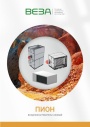
Каталог продукции Веза 2026 - Воздухонагреватели газовые ПИОН. pdf, 6.55 Mb
Каталог газовых воздухонагревателей ПИОН: назначение, конструкция и исполнения, технические характеристики, габаритные размеры, обозначение при заказе. -
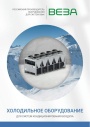
Каталог продукции Веза 2026 - Холодильное оборудование для систем кондиционирования воздуха. pdf, 4.97 Mb
Каталог холодильного оборудования Веза для систем кондиционирования: чиллеры, компрессорно-конденсаторные блоки, фанкойлы и другое оборудование — технические характеристики, габаритные размеры, обозначение при заказе. -
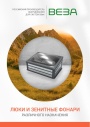
Каталог продукции Веза 2025 - Люки и зенитные фонари различного назначения. pdf, 8.45 Mb
Каталог люков дымоудаления и зенитных фонарей Веза различного назначения: конструкция и исполнения, приводы и автоматика, технические характеристики, габаритные размеры.
Новое в инструкциях
-
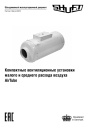
Компактные приточные установки Shuft серии AirTube. pdf, 350.53 Kb
Модели: AirTube 160, 200, 250, 315. Паспорт (объединённый эксплуатационный документ): описание устройства, монтаж, подключение электропитания, схемы электрических соединений, обслуживание, поиск и устранение неисправностей, гарантия, технические данные. -
Приточные установки Shuft серии Eco-Slim. pdf, 8.64 Mb
Модели: Eco-Slim 350, 700, 1100, 1100 W. Паспорт (объединённый эксплуатационный документ) установок с электрическим и водяным нагревателем: технические характеристики, монтаж, схема электрического подключения, обслуживание, пульт управления «Oazis», неисправности. -
Канальные фанкойлы Shuft серии SFF. pdf, 1.91 Mb
Модели: SFF-200G50 … SFF-1400G50. Инструкция по эксплуатации средненапорных канальных фанкойлов: внешние виды и размеры, технические характеристики, монтаж, электропроводка, техническое обслуживание, устранение неисправностей.