

Инструкция на Полупромышленные кондиционеры Digital Inverter
Полупромышленные кондиционеры Digital Inverter . Канальные высоконапорные блоки RAV-SM1103DT-A, RAV-SM1403DT-A, RAV-SM1603DT-A. Инструкция по обслуживанию и ремонту.
Смотрите также: Инструкция по обслуживанию и ремонту →
Загружаем документ…
Текст инструкции
-
FILE NO. A07-009
SERVICE MANUAL AIR-CONDITIONER SPLIT TYPE OUTDOOR UNIT <DIGITAL INVERTER> RAV-SM1603AT-E RAV-SM1603ATZ-E RAV-SM1603ATZG-E INDOOR UNIT <DIGITAL INVERTER> RAV-SM1403DT-A RAV-SM1603DT-A ∗ Refer to the Service Manual with File No. A06-010 for Model RAV-SM1403AT-E, and refer to the Service Manual with…
-
SAFETY CAUTION
The important contents concerned to the safety are described on the product itself and on this Service Manual. Please read this Service Manual after understanding the described items thoroughly in the following contents (Indications/Illustrated marks), and keep them. [Explanation of indications]…
-
WARNING
Check earth wires. Before troubleshooting or repair work, check the earth wire is connected to the earth terminals of the main unit, otherwise an electric shock is caused when a leak occurs. If the earth wire is not correctly connected, contact an electric engineer for rework. Do not modify the…
-
WARNING
Insulator check Ventilation After the work has finished, be sure to use an insulation tester set (500V Megger) to Ω or more between the charge section and the non-charge check the resistance is 2MΩ metal section (Earth position). If the resistance value is low, a disaster such as a leak or electric…
-
This air conditioner adopts a new HFC type refrigerant (R410A) which does not deplete the ozone layer. 1. Safety Caution Concerned to New Refrigerant The pressure of R410A is high 1.6 times of that of the former refrigerant (R22). Accompanied with change of refrigerant, the refrigerating oil has…
-
4. Tools
1. Required Tools for R410A Mixing of different types of oil may cause a trouble such as generation of sludge, clogging of capillary, etc. Accordingly, the tools to be used are classified into the following three types. 1) Tools exclusive for R410A (Those which cannot be used for conventional…
-
1. SPECIFICATIONS
1-1. Indoor Unit 1-1-1. High Static Duct Type <Single type> Indoor unit RAV- SM1403DT-A SM1403DT-A Outdoor unit RAV- SM1403AT-E SP1404AT-E SM1603AT(Z)(ZG)-E Cooling capacity (kW) 12.5 13.0 14.3 Heating capacity (kW) 14.0 14.0 16.0 Model Power supply 1 phase 240V, 50Hz Running current Cooling (A)…
-
1-1-2. 4-way Air Discharge Cassette Type
<Single type> Indoor unit RAV- SM1604UT-E Outdoor unit RAV- SM1603AT(Z)(ZG)-E Cooling capacity (kW) 14.0 Heating capacity (kW) 16.0 Model Power supply 1 phase 230V (220 – 240V) 50Hz Running current Cooling Electrical characteristics (A) 21.38 – 19.69 Power consumption (kW) 4.49 Power factor (%) 95…
-
RAV-
SM804UT-E Indoor unit 2 RAV- SM804UT-E Outdoor unit RAV- SM1603AT(Z)(ZG)-E Cooling capacity (kW) 14.0 Heating capacity (kW) 16.0 Model Indoor unit Power supply 1 phase 230V (220 – 240V) 50Hz Running current Cooling Electrical characteristics (A) 21.48 – 19.69 Power consumption (kW) 4.49 Power factor…
-
RAV-
SM564UT-E Indoor unit 2 RAV- SM564UT-E Indoor unit 3 RAV- SM564UT-E Outdoor unit RAV- SM1603AT(Z)(ZG)-E Cooling capacity (kW) 14.0 Heating capacity (kW) 16.0 Model Indoor unit Power supply 1 phase 230V (220 – 240V) 50Hz Running current Cooling Electrical characteristics (A) 21.48 – 19.69 Power…
-
1-1-3. Concealed Duct Type
<Twin type> Indoor unit 1 RAV- SM802BT-E Indoor unit 2 RAV- SM802BT-E Outdoor unit RAV- SM1603AT(Z)(ZG)-E Cooling capacity (kW) 14.0 Heating capacity (kW) 16.0 Model Indoor unit Power supply 1 phase 230V (220 – 240V) 50Hz Running current Cooling Electrical characteristics (A) 24.50 – 22.46 Power…
-
RAV-
SM562BT-E Indoor unit 2 RAV- SM562BT-E Indoor unit 3 RAV- SM562BT-E Outdoor unit RAV- SM1603AT(Z)(ZG)-E Cooling capacity (kW) 14.0 Heating capacity (kW) 16.0 Model Indoor unit Power supply 1 phase 230V (220 – 240V) 50Hz Running current Cooling Electrical characteristics (A) 24.50 – 22.46 Power…
-
1-1-4. Under Ceiling Type
<Twin type> Indoor unit 1 RAV- SM802CT-E Indoor unit 2 RAV- SM802CT-E Outdoor unit RAV- SM1603AT(Z)(ZG)-E Cooling capacity (kW) 14.0 Heating capacity (kW) 16.0 Model Indoor unit Power supply 1 phase 230V (220 – 240V) 50Hz Running current Cooling Electrical characteristics (A) 23.88 – 21.89 Power…
-
RAV-
SM562CT-E Indoor unit 2 RAV- SM562CT-E Indoor unit 3 RAV- SM562CT-E Outdoor unit RAV- SM1603AT(Z)(ZG)-E Cooling capacity (kW) 14.0 Heating capacity (kW) 16.0 Model Indoor unit Power supply 1 phase 230V (220 – 240V) 50Hz Running current Cooling Electrical characteristics (A) 23.88 – 21.89 Power…
-
1-1-5. High Wall Type
<Twin type> Indoor unit 1 RAV- SM802KRT-E Indoor unit 2 RAV- SM802KRT-E Outdoor unit RAV- SM1603AT(Z)(ZG)-E Cooling capacity (kW) 14.0 Heating capacity (kW) 16.0 Model Indoor unit Power supply 1 phase 230V (220 – 240V) 50Hz Running current Cooling Electrical characteristics (A) 24.40 – 22.37 Power…
-
RAV-
SM562KRT-E Indoor unit 2 RAV- SM562KRT-E Indoor unit 3 RAV- SM562KRT-E Outdoor unit RAV- SM1603AT(Z)(ZG)-E Cooling capacity (kW) 14.0 Heating capacity (kW) 16.0 Model Indoor unit Power supply 1 phase 230V (220 – 240V) 50Hz Running current Cooling Electrical characteristics (A) 24.40 – 22.37 Power…
-
1-1-6. Compact 4-way Cassette (600 × 600) Type
<Triple type> Indoor unit 1 RAV- SM562MUT-E Indoor unit 2 RAV- SM562MUT-E Indoor unit 3 RAV- SM562MUT-E Outdoor unit RAV- SM1603AT(Z)(ZG)-E Cooling capacity (kW) 14.0 Heating capacity (kW) 16.0 Model Indoor unit Power supply 1 phase 230V (220 – 240V) 50Hz Running current Cooling Electrical…
-
1-1-7. Slim Duct Type
<Triple type> Model Indoor unit 1 RAV- SM564SDT-E Indoor unit 2 RAV- SM564SDT-E Indoor unit 3 RAV- SM564SDT-E Outdoor unit RAV- SM1603AT(Z)(ZG)-E Cooling capacity (kW) 14.0 Heating capacity (kW) 16.0 Indoor unit Power supply 1 phase 230V (220 – 240V) 50Hz Running current Cooling (A) 23.88 – 21.89…
-
1-2. Outdoor Unit
Model name RAV-SM1603AT(Z)(ZG)-E Power supply 1 phase 230V (220 – 240V) 50Hz Type Compressor Hermetic compressor Motor (kW) Pole 4 Refrigerant charged (kg) Refrigerant control Inter connecting pipe Standard length (m) 7.5 Min. length (m) 5 Max. total length (m) 50 Additional refrigerant charge under…
-
1-3. Operation Characteristic Curve
• Operation characteristic curve RAV-SM1603AT-E, RAV-SM1603ATZ-E, RAV-SM1603ATZG-E <Cooling> <Heating> 25 23.7 28.2 Current (A) Current (A) 30 28.2 • Conditions Indoor : DB27°C/WB19°C Outdoor : DB35°C Air flow : High Pipe length : 7.5m 230V • Conditions Indoor : DB20°C Outdoor : DB7°C/WB6°C Air flow…
-
2. CONSTRUCTION VIEWS (EXTERNAL VIEWS)
2-1. Indoor Unit RAV-SM1403DT-A, RAV-SM1603DT-A 200 or more Service work space 704 664 (52) Air flow Hung-up plate (915) 965 (Bolt pitch) (50) 100 or more Drain trap (900) 1050 Air flow 950 (Bolt pitch) 200 1300 or more Check port 400 × 800 600 (35) (52) Plug (Port for check and clean) (36) (53)…
-
2 Power supply inlet hole Ø38 Kockout hole A legs Air outlet 70 383 port 17.5 Note Name Refrigerant piping hole Indoor/Outdoor unit connecting wire inlet hole Mounting bolt hole (Ø12 × 17 long hole) Drain hole (Ø25) B legs 46 128 17.5 365 Air inlet port 60 Mounting bolt hole (Ø12 × 17 U-shape hole)…
-
RBC-TWP30E2, RBC-TWP50E2 (Simultaneous Twin)
-
RBC-TRP100E (Simultaneous Triple)
<Gas side> Header assembly 300 80 Inner diameter Ø15.9 80 100 Inner diameter Ø25.4 100 <Liquid side> Branch pipe assembly Inner diameter Ø9.52 100 Inner diameter Ø12.7 100 Insulator Gas side socket Liquid side socket Ø15.9 Ø12.7 Ø9.5 Ø6.4 Ø15.9 Ø25.4 Ø9.5 Ø12.7 (External diameter) (External…
-
3. SYSTEMATIC REFRIGERATING CYCLE DIAGRAM
3-1. Indoor Unit <Indoor unit to be connected to RAV-SM1403DT-A, RAV-SM1603DT-A> • Single type (Combination of one indoor unit and one outdoor unit) Distributor (Strainer incorporated) Indoor unit TCJ sensor Air heat exchanger TC sensor Refrigerant pipe at liquid side ØB Refrigerant pipe at gas side…
-
• Single type (Combination of one indoor unit and one outdoor unit) Distributor (Strainer incorporated) Indoor unit TCJ sensor Air heat exchanger TC sensor Refrigerant pipe at liquid side Outer diameter Ø9.5 Refrigerant pipe at gas side Outer diameter Ø15.9 Heating Cooling To outdoor unit To outdoor…
-
3-2. Outdoor Unit
RAV-SM1603AT-E, RAV-SM1603ATZ-E, RAV-SM1603ATZG-E TO sensor TS sensor PMV Strainer TE sensor Check joint Capillary Ø4 ×Ø3 (6 pcs.) Cooling: High pressure Heating: Low pressure Heat exchanger Ø8, 2 rows, 52 stages FP1.45, flat fin TD sensor Distributor Refrigerant pipe at liquid side Ø9.5 Packed…
-
4. WIRING DIAGRAM
4-1. Indoor Unit Noise absorber RAV-SM1403DT-A, RAV-SM1603DT-A YEL BLU ORN WHI 8 DP Relay 43F3 WHI H M 1 1 L 1 1 CS 1 3 CN030 (RED) UL RY007 Relay 43F2 Noise absorber Noise absorber 7 Fan 9 CN083 (WHI) 9 WHI DP CN033 3 CN068 (GRN) 3 (BLU) WHI 8 RY004 1 CN034 (GRY) Relay 43F1 RY006 WHI RY002 RY001…
-
Power supply 220-240V
Single phase 50Hz Power supply 220-240V Single phase 50Hz Outdoor unit Outdoor unit L N L N Indoor A B unit Indoor unit No.1 (Master) A B Earth screw Indoor unit No.2 (Sub) A B A B Wired remote controller A B Wired remote controller • Triple type Power supply 220-240V Single phase 50Hz Outdoor unit…
-
4-2. Outdoor Unit
RAV-SM1603AT-E, RAV-SM1603ATZ-E, RAV-SM1603ATZG-E CN06 WHI CN08 WHI WHI Noise Filter P.C. Board MCC-1551 3 3 WHI CN04 WHI CN01 CN03 CN02 P01 IPDU P.C. Board MCC-1535 RED 5 5 CN09 CN13 RED BLK CN10 1 1 CN11 RED WHI CN05 WHI CN22 BLU NA NA LB LB CM BLK CN04 WHI NB NB Reactor CN20 CN21 CN01 WHI 1 1 RED…
-
4-3. Fan Characteristics
Current value as a criterion, adjust the air volume value to become within the range of the chart below. <RAV-SM1403DT-A> <RAV-SM1603DT-A> Static pressure (Pa) (unit) 30 40 m³/h Hi 3,480 3,300 2,500 2,330 2,100 l/s CMM 58.0 55.0 41.6 38.8 35.0 2,670 2,500 2,100 1,900 m³/h Med 2,700 l/s CMM 45.0 44.5…
-
5. SPECIFICATIONS OF ELECTRICAL PARTS
-
6. REFRIGERANT R410A
This air conditioner adopts the new refrigerant HFC (R410A) which does not damage the ozone layer. The working pressure of the new refrigerant R410A is 1.6 times higher than conventional refrigerant (R22). The refrigerating oil is also changed in accordance with change of refrigerant, so be careful…
-
Table 6-2-1 Thicknesses of annealed copper pipes
Thickness (mm) Nominal diameter Outer diameter (mm) R410A R22 1/4 6.4 0.80 0.80 3/8 9.5 0.80 0.80 1/2 12.7 0.80 0.80 5/8 15.9 1.00 1.00 1. Joints For copper pipes, flare joints or socket joints are used. Prior to use, be sure to remove all contaminants. a) Flare Joints Flare joints used to connect…
-
c) Insertion of Flare Nut
d) Flare Processing Make certain that a clamp bar and copper pipe have been cleaned. By means of the clamp bar, perform the flare processing correctly. Use either a flare tool for R410A or conventional flare tool. Flare processing dimensions differ according to the type of flare tool. When using a…
-
to 4 45˚ B A C 43˚ D to 4 5˚ Fig. 6-2-2 Relations between flare nut and flare seal surface 2. Flare Connecting Procedures and Precautions a) Make sure that the flare and union portions do not have any scar or dust, etc. b) Correctly align the processed flare surface with the union axis. c) Tighten…
-
6-3. Tools
6-3-1. Required Tools Refer to the “4. Tools” (Page 8) 6-4. Recharging of Refrigerant When it is necessary to recharge refrigerant, charge the specified amount of new refrigerant according to the following steps. Recover the refrigerant, and check no refrigerant remains in the equipment. When the…
-
1) Be sure to make setting so that liquid can be charged
2) When using a cylinder equipped with a siphon, liquid can be charged without turning it upside down. It is necessary for charging refrigerant under condition of liquid because R410A is mixed type of refrigerant. Accordingly, when charging refrigerant from the refrigerant cylinder to the equipment…
-
2. Characteristics required for flux
6-5-3. Brazing • Activated temperature of flux coincides with the brazing temperature. • Due to a wide effective temperature range, flux is hard to carbonize. • It is easy to remove slag after brazing. • The corrosive action to the treated metal and brazing filler is minimum. • It excels in coating…
-
Instruction of Works: The existing R22 and R407C piping can be reused for our digital inverter R410A products installations. NOTE) Confirmation of existence of scratch or dent of the former pipes to be applied and also confirmation of reliability of the pipe strength are conventionally referred to…
-
6-6-5. Final Installation Checks
Is there no scratch or dent on the existing pipes? Existing pipe: NO * Use a new pipes. NO Is it possible to operate the existing air conditioner? YES ∗ After the existing air conditioner operated in cooling mode for approx. 30 minutes or longer*, recover the refrigerant. ∗ For cooling the pipes and…
-
6-6-6. Handling of Existing Pipe
When using the existing pipe, carefully check it for the following: • Wall thickness (within the specified range) • Scratches and dents • Water, oil, dirt, or dust in the pipe • Flare looseness and leakage from welds • Deterioration of copper pipe and heat insulator Cautions for using existing pipe…
-
6-6-7. Recovery Method of Refrigerant
RAV-SP1404AT(Z)(ZG)-E RAV-SM1603AT(Z)(ZG)-E • Use the refrigerant recovery switch SW801 on the P.C. board of the outdoor unit to recover refrigerant when the indoor unit or outdoor unit is moved. • Use the refrigerant recovery switch SW802 on the P.C. board of the outdoor unit to recover refrigerant…
-
6-7. Tolerance of Pipe Length and Pipe Head
n Twin system Total length (L + a or L + b) 50 m Branch pipe length (a, b) 15 m Maximum difference between indoor units (b – a, or a - b) 10 m Between indoor units ( ∆ h) 0.5 m Pipe length (one way) Refrigerant pipe specification Height difference Between indoor unit and outdoor unit When outdoor…
-
n Triple system
Total length (L + a, L +b, L+c) 50 m Branch pipe length (a, b, c) 15 m Maximum difference between indoor units (|a – b|, |b – c|, |c – d|) 10 m Between indoor units ( ∆ h) 0.5 m Pipe length (one way) Refrigerant pipe specification Height difference Between indoor unit and outdoor unit When outdoor…
-
6-8. Additional Refrigerant Amount
n Twin system <Formula for Calculating Additional Refrigerant Amount> Do not remove the refrigerant even if the additional refrigerant amount becomes minus result as a result of calculations by the following formula and operate the air conditioner as it is. Additional refrigerant amount (kg) = Main…
-
n Triple system
<Formula for Calculating Additional Refrigerant Amount> Do not remove the refrigerant even if the additional refrigerant amount becomes minus result as a result of calculations by the following formula and operate the air conditioner as it is. Additional refrigerant amount (kg) = Main piping…
-
6-9. Piping Materials and Sizes
n Twin system Use copper tube of Copper and copper alloy seamless pipes and tubes, with 40mg/10m or less in the amount of oil stuck on inner walls of pipe and 0.8mm in pipe wall thickness for diameters for diameters 6.4, 9.5 and12.7mm and 1.0mm, for diameter 15.9mm. Never use pipes of thin wall…
-
6-10. Branch Pipe
n Twin system Now the refrigerant pipe is installed using branch pipes supplied as accessories. • Bend and adjust the refrigerant piping so that the branch pipes and pipe after branching become horizontal. • Fix the branch pipes onto a wall in a ceiling or onto a column. • Provide a straight pipe…
-
7. INDOOR CONTROL CIRCUIT
7-1. Indoor Controller Block Diagram RAV-SM1403DT-A, RAV-SM1603DT-A 7-1-1. Connection of Main (Sub) Remote Controller Main (Sub) Master remote controller (Max. 2 units) Display part LCD Function setup Display part LCD CPU Display part LED Power supply circuit A CN2 CPU Key switch *3 Power supply…
-
7-2. Control Specifications
No. Item Outline of specifications 1 When power supply is reset 1) Distinction of outdoor unit When the power supply is reset, the outdoors are distinguished and the control is selected according to the distinguished result. 2 Operation mode selection 1) Based on the operation mode selecting command…
-
Item Room temp. control Remarks Outline of specifications 1) Adjustment range: Remote controller setup temperature (°C) COOL HEAT AUTO Wired type 18 to 29 18 to 29 18 to 29 Wireless type 18 to 30 16 to 30 17 to 27 2) Using the Item code 06, the setup temperature in heating operation can be…
-
Outline of specifications
6 Air speed selection 1) Operation [HH], [L] or [AUTO] is performed by command from the remote controller. 2) The air speed is varied with difference between Ta and Ts while the air speed is set to [AUTO]. Remarks HH > L > UL <COOL> Ta (˚C) Normal cooling Cooling in Cooling/Heating [AUTO] HH (High…
-
Outline of specifications
Remarks 8 Freeze preventive control (Low temperature release) 1) The cooling operation (including Dry operation) is performed as follows based on the detected temperature of Tc sensor or Tcj sensor. When [J] zone is detected for 6 minutes (Following figure), the commanded frequency is decreased from…
-
Outline of specifications
9 High-temp. release control 1) The heating operation is performed as follows based on the detected temperature of Tc sensor or Tcj sensor. • When [M] zone is detected, the commanded frequency is decreased from the real operation frequency. After then the commanded frequency changes every 30 seconds…
-
Outline of specifications
13 Filter sign display (Except wireless type) ∗ It is provided on the separately sold type TCB-AX21E2. 1) The operation time of the indoor fan is calculated, the filter reset signal is sent to the remote controller when the specified time (2500H) has passed, and it is displayed on LCD. 2) When the…
-
7-3. Optional Connector Specifications of Indoor P.C. Board
Function Ventilation output Connector No. Pin No. Specifications Remarks 1 DC12V Setting at shipment: Interlock of ON by indoor unit operation, with OFF by stop operation 2 Output (Open collector) ∗ The single operation setting by FAN button on the remote controller is performed on the remote…
-
EEPROM
Indoor/Outdoor communication (Also used for communication of the central control system) Power transformer (Primary side) (AC240V) Remote controller power supply LED – 60 – Optional output Drain pump output Remote controller inter-unit wire Optional power supply EXCT AC fan output TA sensor Outside…
-
7-5. Outdoor Print Circuit Board
RAV-SM1603AT-E, RAV-SM1603ATZ-E, RAV-SM1603ATZG-E Inverter P.C. board <MCC-1535> [IPDU1] Electrolytic condenser (–) Electrolytic condenser (+) +12V Reactor +5V Between fan IPDU and comp IPDU Communication between I/F and comp IPDU +7V Reactor GND Compressor out put – 61 –
-
Noise filter P.C. board <MCC-1551>
-
EEPROM-IC
-
8. CIRCUIT CONFIGURATION AND CONTROL SPECIFICATIONS
8-1. Outdoor Controls 8-1-1. Outline of Main Controls 1. Pulse Motor Valve (PMV) control 1) For PMV with 45 to 500 pulses during operation, respectively. 2) In cooling operation, PMV is controlled with the temperature difference between TS sensor and TC sensor. 3) In heating operation, PMV is…
-
4. Outdoor fan control
-
2) Heating fan control
Q The outdoor fan is controlled by TE sensor, TO sensor and the operation frequency. (From Min. W1 to Max. are controlled according to the following table.) R During 3 minutes after start-up, the fan is fixed with the maximum fan tap corresponding to TE [˚C] zone in the following table. After then…
-
6. Short intermittent operation preventive control
1) For 3 to 10 minutes after operation start, in some cases, the compressor does not stop to protect the compressor even if receiving the thermostat-OFF signal from indoor. However it is not abnormal status. (The operation continuance differs according to the operation status.) 2) When the operation…
-
10. Defrost control
Q In heating operation, defrost operation is performed when TE sensor temperature satisfies any condition in A zone to D zone. R The defrost operation is immediately finished if TE sensor temperature has become 12°C or more, or it also is finished when condition of 7°C < TE < 12°C has continued for…
-
9. INDOOR UNIT TROUBLESHOOTING
9-1. Summary of Troubleshooting <Wired remote controller type> 1. Before troubleshooting 1) Required tools/instruments • + and – screwdrivers, spanners, radio cutting pliers, nippers, push pins for reset switch • Tester, thermometer, pressure gauge, etc. 2) Confirmation points before check a) The…
-
9-2. Troubleshooting
9-2-1. Check Code List (Indoor) (Indoor unit detected) Check code indication Air conditioner operation Representative defective position TCC-LINK central & Wired remote controller – 70 – E03 Regular communication error between indoor and remote controller E04 E08 E10 Indoor/Outdoor serial error…
-
Error mode detected by indoor unit
Operation of diagnostic function Check code E03 Cause of operation No communication from remote controller (including wireless) and communication adapter Status of air conditioner Judgment and measures Condition 1. Check cables of remote controller and communication adapters. Stop Displayed when…
-
Error mode detected by remote controller or central controller (TCC-LINK)
Operation of diagnostic function Check code Cause of operation Status of air conditioner Judgment and measures Condition Power supply error of remote controller, Indoor EEPROM error 1. Check remote controller inter-unit wiring. Not displayed at all (Operation on remote controller is impossible.) No…
-
9-2-2. Diagnostic Procedure for Each Check Code (Indoor Unit)
Check code [E01 error] Is inter-unit cable of A and B normal? NO Correct inter-unit cable of remote controller YES Correct connection of connector. Check circuit wiring. NO Check power connection of indoor unit. (Turn on power again.) NO Check indoor P.C. board (MCC-1403). Defect → Replace YES…
-
[E04 error]
NO Does outdoor operate? Is group address setup of remote controller correct? YES NO Check Item code [14]. YES Are wiring in indoor unit and 1, 2, 3 inter-unit cables correct? NO Correct wiring and inter-unit cables. NO Correct wiring of connector and terminal blocks. NO Check indoor P.C. board.…
-
[E18 error]
Is inter-unit cable of A and B normal? NO Correct inter-unit cable of remote controller. YES Correct connection of connector. Check circuit wiring. NO Check power connection status of indoor unit (Connect again). YES Is there no disconnection or contact error of connector on harness from terminal…
-
[L20 error]
Are wiring connections to communication lines U3 and U4 normal? NO Correct wiring connection. YES Is not the multiple same central control system addresses connected? YES Correct central control system address. NO Check central controller (including network adapter) and indoor P.C. board (MCC-1403).…
-
[P10 error]
Is connection of float switch connector (Indoor control board CN34) normal? NO Correct connection of connector. YES YES NO Does float switch work? Is circuit wiring normal? YES NO Check and correct wiring and wire circuit. NO Does drain pump work? YES Is power of drain pump turned on? ∗ NO YES Are…
-
[P19 error]
Temperature sensor check TE sensor CN601 TS sensor CN600 Indoor TC sensor Defect → Correct and repair YES Is operation of 4-way valve normal? (Check pipe temp., etc. in cooling/heating operation.) NO NO Is the coil resistance value of 4-way valve between 1.3 and 1.6kΩ? Replace coil of 4-way valve.…
-
[F02 error]
Is connection of TC sensor connector (CN101 on Indoor P.C. board) correct? NO Correct connection of connector. YES Are characteristics of TC sensor resistance value normal? YES NO Replace TC sensor. ∗ Refer to TC sensor (Temperature-Resistance value characteristic table) Check indoor P.C. board…
-
[C06 error] (TCC-LINK central controller)
NO Are U3 and U4 communication lines normal? Correct communication line. YES NO ∗1 Correct connection of connector. Is connection of connector normal? YES ∗1 TCC-LINK central: CN51 of TCC-LINK adapter P.C. board (MCC-1440) and CN050 of indoor P.C. board NO Are A and B communication lines normal?…
-
[E03 error] (Master indoor unit)
[E03 error] is detected when the indoor unit cannot receive a signal from the remote controller (also central controller). Check A and B remote controllers and communication lines of the central control system U3 and U4. As communication is impossible, this check code [E03] is not displayed on the…
-
Temperature sensor
Temperature – Resistance value characteristic table TA, TC, TCJ, TE, TS, TO sensors TD, TL sensors Representative value Representative value Ω) Resistance value (kΩ Temperature (°C) (Minimum value) (Standard value) (Maximum value) Ω) Resistance value (kΩ Temperature (°C) (Minimum value) (Standard…
-
10. OUTDOOR UNIT TROUBLESHOOTING
10-1. Summary of Troubleshooting <Wired remote controller type> 1. Before troubleshooting 1) Required tools/instruments • + and – screwdrivers, spanners, radio cutting pliers, nippers, push pins for reset switch • Tester, thermometer, pressure gauge, etc. 2) Confirmation points before check a) The…
-
<Wireless remote controller type>
1. Before troubleshooting 1) Required tools/instruments • + and – screwdrivers, spanners, radio cutting pliers, nippers, etc. • Tester, thermometer, pressure gauge, etc. 2) Confirmation points before check a) The following operations are normal. 1. Compressor does not operate. • Is not 3-minutes…
-
10-2. Troubleshooting
10-2-1. Outline of Judgment The primary judgment to check whether a trouble occurred in the indoor unit or outdoor unit is carried out with the following method. Method to judge the erroneous position by flashing indication on the display part of the indoor unit (sensors of the receiving part) The…
-
Lamp indication
Operation Timer Ready F01 F02 Alternate flash Operation Timer F10 Ready F04 F06 Alternate flash Operation Timer Cause of trouble occurrence Check code F08 Heat exchanger sensor (TCJ) error Heat exchanger sensor (TC) error Heat exchanger sensor (TA) error Indoor unit sensor error Discharge…
-
10-2-2. Others (Other than Check Code)
Lamp indication Operation Timer Check code Cause of trouble occurrence Ready — During test run — Disagreement of cool/heat (Automatic cool/heat setting to automatic cool/heat prohibited model, or setting of heating to cooling-only model) Simultaneous flash Operation Timer Ready Alternate flash New…
-
10-2-3. Check Code List (Outdoor)
ALT (Alternate): Alternate flashing when there are two flashing LED Remote controller indication ¡ : Go on, ¥ : Flash, l : Go off SIM (Simultaneous): Simultaneous flashing when there are two flashing LED Sensor lamp part Block indication Representative defective position Explanation of error…
-
ALT (Alternate): Alternate flashing when there are two flashing LED
Remote controller indication F01 F02 F10 F29 P01 P10 P12 P31 — Sensor lamp part — Representative defective position Detection ALT Indoor unit Heat exchanger sensor (TCJ) error Indoor Open/Short of heat exchanger (TCJ) was detected. ALT Indoor unit Heat exchanger sensor (TC) error Indoor Open/Short…
-
Error mode detected by indoor unit
Operation of diagnostic function Check code Cause of operation E03 No communication from remote controller (including wireless) and communication adapter E04 The serial signal is not output from outdoor unit to indoor unit. • Miswiring of inter-unit wire • Defective serial sending circuit on outdoor…
-
Error mode detected by remote controller or central controller (TCC-LINK)
. Operation of diagnostic function Check code Cause of operation Status of air conditioner — Power supply error of remote controller, Indoor EEPROM error 1. Check remote controller inter-unit wiring. 2. Check remote controller. 3. Check indoor power wiring. 4. Check indoor P.C. board. 5. Check…
-
Error mode detected by outdoor unit
Operation of diagnostic function Check code Cause of operation Indoor unit Judgment anAd measures Status of air conditioner Condition F04 Disconnection, short of discharge temp. sensor (TD) Stop Displayed when error is detected 1. Check discharge temp. sensor (TD). 2. Check outdoor P.C. board. F06…
-
10-2-4. Distinction of error mode by LED indication of outdoor unit
On the Type AP112, AP140 and AP160, a Dip switch (SW801) and LED are provided on the P.C. board of the outdoor unit. Exchanging this Dip switch enables users to know the status of the outdoor unit in that time. Lighting status of LED enables users to know the distinction stage before trouble of the…
-
You can perform fault diagnosis of the outdoor unit with the LEDs on the P.C. board of the outdoor unit in addition to check codes displayed on the wired remote controller of the indoor unit. Use the LEDs and check codes for various checks. Details of check codes displayed on the wired remote…
-
10-2-5. Diagnostic Procedure for Each Check Code (Indoor Unit)
Check code [E01 error] Is inter-unit cable of A and B normal? NO Correct inter-unit cable of remote controller YES Correct connection of connector. Check circuit wiring. NO Check power connection of indoor unit. (Turn on power again.) NO Check indoor P.C. board (MCC-1570). Defect → Replace YES…
-
[E04 error]
NO Does outdoor unit operate? YES NO Check item code [14]. Is setup of group address correct? YES NO Are 1, 2, 3 inter-unit cables normal? Correct inter-unit cable. YES Are connections from connectors of inter-terminal blocks (1, 2, 3) of indoor/outdoor units normal? NO Correct connection of…
-
[E10 error]
YES Check power supply voltage. Correct lines. Check and eliminate noise, etc. Is there no disorder of power supply? NO Check indoor control P.C. board. Defect → Replace [E18 error] Is inter-unit cable of A and B normal? NO Correct inter-unit cable of remote controller. YES Correct connection of…
-
[L09 error]
Is not yet capacity setting of indoor unit set up? YES Set capacity data of indoor unit. (Setup item code (DN)=11) NO Check indoor P.C. board. Defect → Replace [L20 error] Are wiring connections to communication lines X and Y normal? NO Correct wiring connection. YES Is the central controller [98]…
-
[b7 error] (Central controller)
NO Is group operation carried out? YES Is there check code on the follower unit of main/sub remote controllers? NO Check indoor P.C. board. Defect à Replace YES Correct wiring circuit of the connector connection. YES Check the corresponding indoor unit and outdoor unit. [P01 error] Isn’t there any…
-
[P10 error]
Is connection of float switch connector (Indoor control board CN34) normal? NO Correct connection of connector. YES YES NO Does float switch work? Is circuit wiring normal? YES NO Check and correct wiring and wire circuit. NO Does drain pump work? YES Is power of drain pump turned on? ∗ NO YES Check…
-
[P12 error]
Turn off the power. Is there no connection error or disconnection on connectors CN333 and CN334 of indoor unit P.C. board (MCC-1402)? YES Correct connection of connector. CN333 NO Remove connectors CN333 and CN334 of indoor unit P.C. board (MCC-1402). CN334 Does the fan rotate without trouble when…
-
[P22 error]
Are connections of CN300, CN301, CN302 and CN303 of P.C. board correct? Correct connection of connector. YES Does the fan rotate without trouble when handling the fan with hands under condition of removing CN300, CN301, CN302 and CN303 from P.C. board? NO CN301, ∗ CN303 YES The status that the…
-
[P19 error]
Is operation of 4-way valve normal? NO YES YES Is flow of refrigerant by electron expansion valve normal? NO NO 4-way valve coil conduction? YES Is 4-way valve coil terminal 200V Check 4-way valve Defect → Replace NO YES Is circuit cable normal? Connection of CN01 on CDB and CN13 on IPDU (Both…
-
[F01 error]
Is connection of TCJ sensor connector (Indoor P.C. board CN102) normal? NO Correct connection of connector. YES Are characteristics of TCJ sensor resistance value normal? ∗ NO Replace TCJ sensor. YES ∗ Refer to 10-2-6. Relational graph of Check indoor P.C. board. Defect → Replace temperature sensor…
-
[P29 error]
Are connections of cable/connector normal? NO Check and correct circuit cabling such as cabling to compressor. YES NO Is not earthed? Is compressor normal? YES YES NO Is not winding shorted? (Is resistance between windings 0.6 to 1.2Ω?) YES NO YES Is not winding opened? NO Check IPDU P.C. board.…
-
[F08 error]
NO Is connection of TO sensor connector of CDB CN601 normal? Correct connection of connector. YES NO Are characteristics of TO sensor resistance value normal? ∗ Replace TO sensor. YES ∗ Refer to relational graph of temperature sensor resistance value Check CDB. Defect → Replace and temperature…
-
[P03 error]
Is protective control such as discharge temprelease control normal? NO Are connections of cable/connector normal? NO Correct the cabling and connection of connector. YES YES Check parts. Defect → Replace Is charged refrigerant amount normal? NO Check and correct the charged refrigerant amount. YES…
-
[P04 error]
Is high-voltage protective operation by TE sensor normal? NO YES Is connection of cabling connector normal? NO Correct connection of cabling connector. YES Check TE sensor. Defect → Replace NO Does cooling outdoor fan normally operate? YES Is connection of connector normal? NO Correct connection of…
-
[97 error] (Central controller)
NO Are X and Y communication lines normal? Correct communication line. YES Are CN01, CN02 and CN03 of the network adapter P.C. board (MCC-1401) and CN309 and CN41 connectors correctly connected? NO Correct connection of connector. YES NO Are A and B communication lines normal? Check connection of A…
-
[E03 error] (Master indoor unit)
[E03 error] is detected when the indoor unit cannot receive a signal sent from the main remote controller (and central controller). In this case, check the communication cables of the remote controllers A and B, the central control system X and Y. As communication is disabled, [E03] is not displayed…
-
10-2-6. Relational Graph of Temperature Sensor Resistance Value and Temperature
-
11-1. Indoort Unit <Note: when replacing the P.C. board for indoor unit servicing> The nonvolatile memory (hereafter called EEPROM, IC503) on the indoor unit P.C. board before replacement includes the model specific type information and capacity codes as the factory-set value and the important…
-
[1] Setting data read out from EEPROM
The setting data modified on the site, other than factory-set value, stored in the EEPROM shall be read out. Step 1 Push SET , CL and TEST button on the remote controller simultaneously for more than 4 seconds. ∗ When the group operation control is performed, the unit No. displayed for the first…
-
[3] Writing the setting data to EEPROM
The settings stored in the EEPROM of the P.C. board for indoor unit servicing are the factory-set values. Step 1 Push SET , CL and TEST buttons on the remote controller simultaneously for more than 4 seconds. ∗ In the group control operation, the unit No. displayed for the first time is the header…
-
Table 1
DN Item Setting data Factory-set value 01 Filter sign lighting time Depending on Type 02 Filter pollution leve 0000: standard 03 Central control address 0099: Not determined 06 Heating suction temperature shift 0002: +2°C (flooring installation type: 0) OF Cooling only 0000: Heat pump 10 Type…
-
12. SETUP AT LOCAL SITE AND OTHERS
12-1. Indoor Unit 12-1-1. Test Run Setup on Remote Controller <Wired remote controller> TEST 1. When pushing button on the remote controller for 4 seconds or more, “TEST” is displayed on LC display. ON / OFF Then push button. • “TEST” is displayed on LC display during operation of Test Run. • During…
-
1. D02 (Red) • Goes on at the same time when power was turned on (Main microcomputer operates and goes on.) • Flashes with 1-second interval (every 500ms): When EEPROM is not provided or writing was an error. • Flashes with 10-seconds interval (every 5S): When the mode is DISP 2. D203 (Red) • Goes…
-
Function selection item No. (DN) list
DN Item 01 Filter sign lighting time 0000: None 0002: 2500H 0004: 10000H 03 Central control address 0001: No.1 unit 0099: Undecided 06 Heating suction temp. shift 10 Type 0000: (1-way air discharge cassette) 0001: (4-way air discharge cassette) to 0037 According to model type 11 Indoor unit capacity…
-
12-1-5. Wiring and Setting of Remote Controller Control
2-remote controller control (Controlled by 2 remote controllers) This control is to operate 1 or multiple indoor units are operated by 2 remote controllers. (Max. 2 remote controllers are connectable.) (Setup method) One or multiple indoor units are controlled by 2 remote controllers. (Max. 2 remote…
-
12-1-6. Monitor Function of Remote Controller Switch
n Calling of sensor temperature display <Contents> Each data of the remote controller, indoor unit and outdoor unit can be understood by calling the service monitor mode from the remote controller. <Procedure> 1 Push CL TEST + buttons simultaneously for 4 seconds to call the service monitor mode.…
-
n Calling of error history
<Contents> The error contents in the past can be called. <Procedure> 1 Push SET TEST TEMP. + buttons simultaneously for 4 seconds or more to call the service check mode. Service Check goes on, the item code 01 is displayed, and then the content of the latest alarm is displayed. The number and error…
-
n Indoor unit power-ON sequence
• The unit without power feed waits entirely → Waiting status is released by system start • Reboot when power is fed on the way Power ON <By indoor unit which receives power feed from outdoor unit> <Automatic address judgment> Not normal NO 3 minutes elapse Gr construction check YES Normal ∗ Gr…
-
12-2. Setup at Local Site / Others
Model name: TCB-PCNT30TLE2 12-2-1. TCC-LINK Adapter (For TCC-LINK Central Control) 1. Function This model is an optional P.C. board to connect the indoor unit to TCC-LINK (Central controller). 2. Microprocessor block diagram Indoor unit Central controller TCC-LINK adapter P.C. board CN050 Indoor…
-
4. Wiring specifications
• Use 2-core with no polar wire. • Match the length of wire to wire length of the central Size No. of wires control system. Up to 1000m: twisted wire 1.25mm2 If mixed in the system, the wire length is lengthened 2 Up to 2000m: twisted wire 2.0mm2 with all indoor/outdoor inter-unit wire length at…
-
Terminator (SW01) 52 85 7. Address setup In addition to set up the central control address, it is necessary to change the indoor unit number. (Line/Indoor/Group address). For details, refer to TCC-LINK Adapter Installation Manual. 12-3. How to Set up Central Control Address Number When connecting…
-
How to confirm the central control address (New function for AMT32 remote controller)
<Procedure> It can be confirmed even during operation or stopping. 1 Push UNIT LOUVER button for 4 seconds or more. ò 2 In the frame at left side of the remote controller screen, the lighting set contents are displayed. During unset time, '' (At shipment from factory) is displayed. ò 3 After…
-
13. ADDRESS SETUP
13-1. Address Setup Procedure When an outdoor unit and an indoor unit are connected, or when an outdoor unit is connected to each indoor unit respectively in the group operation even if multiple refrigerant lines are provided, the automatic address setup completes with power-ON of the outdoor unit.…
-
13-2. Address Setup & Group Control
<Terminology> Indoor unit No. : N - n = Outdoor unit line address N (Max. 30) - Indoor unit address n (Max. 64) Group address : 0 = Single (Not group control) 1 = Master unit in group control 2 = Sub unit in group control Master unit (= 1) : The representative of multiple indoor units in group…
-
4. Single group operation
• Each indoor unit controls the outdoor unit individually. 2-1 Sub/Header 1-1 Sub/Header 4-1 Master/Header 3-1 Sub/Header 8-1 Sub/Header 5. Multiple groups operation (Manual address setting) 2-1 Sub/Header 1-1 Sub/Header 1-2 Sub/Follower 3-1 Master/Header 3-2 Sub/Follower 3-3 Sub/Follower • Header…
-
13-2-2. Automatic Address Example from Unset Address (No miswiring)
1. Standard (One outdoor unit) 1) Single 2) Twin 3) Triple 1-2 Sub/Header 1-1 Sub/Follower 1-2 Master/Header (1-2) (1-3) 1-3 Master/Follower 1-1 Sub/Follower (1-1) (1-2) (1-1) 1-1 Individual (Master/Header) Only turning on source power supply (Automatic completion) 2. Group operation (Multiple…
-
13-3. Address Setup (Manual Setting from Remote Controller)
In case that addresses of the indoor units will be determined prior to piping work after cabling work • Set an indoor unit per a remote controller. • Turn on power supply. 1 Push SET CL (Example of 2-lines cabling) (Real line: Cabling, Broken line: Refrigerant pipe) Outdoor Outdoor Indoor Indoor…
-
1. To know the indoor unit addresses though position of the indoor unit body is recognized • In case of individual operation (Wired remote controller : indoor unit = 1 : 1) (Follow to the procedure during operation) <Procedure> 1 Push 2 Push ON / OFF button if the unit stops. UNIT LOUVER button.…
-
14. DETACHMENTS
14-1. Indoor Unit REQUIREMENT • At the service replacing time of the heat exchanger, the following tools are necessary. Prepare them before the service work. • Necessary tools: Plus screwdriver, monkey wrench, spanner, etc CAUTION • Be sure to place the heat exchanger at safe and flat place and then…
-
2. How to replace the parts (Continued)
No. 2 Work procedure Remove the foaming part. Explanatory drawing Foaming part Note) Remove the foaming part carefully so that corners of the foaming part of the inner plate are not chipped off by being caught. 3 Remove the right side plates (2) and (3). Note) Remove the side plates so as not to…
-
2. How to replace the parts (Continued)
No. Work procedure 6 Take off the pipe fixing bracket (1) and the drain shield plate. Explanatory drawing Pipe fixing bracket (1) 7 Remove the left side plate. 8 Remove the inner foaming plate and the insulator material. 1) Pull off the insulator material between the drain pan and the mounting…
-
REQUIREMENT
• At the service replacing time of the fan motor, the following tools are necessary. Prepare them before the service work. • Necessary tools: Plus screwdriver, L-shape hexagonal wrench (For ØM8mm (Face to face 4mm)), ratchet wrench (For Ø6mm nut (Face to face 10mm)), monkey wrench, spanner, etc.…
-
4. How to replace the parts (Continued)
No. 2 Work procedure Explanatory drawing Remove the electric parts box. Note) • When keeping the electric parts box, be sure not to damage or take off the sensor lead wire connected to the main unit. Motor lead wire 3 Remove the right side plates (1) and (2). 1) First remove the right side plate (2)…
-
4. How to replace the parts (Continued)
No. 7 Work procedure Explanatory drawing Remove the reinforcing plate. Note) • The reinforcing plate is provided to protect the transportation. Scrap it after unpacking because it is unnecessary to attach when reassembling. Reinforcing plate 8 Take off the screws which fix the bell mouth at the rear…
-
6. How to replace the sensor
No. Work procedure 1 As same as the work procedure of the fan motor replacing, remove the right side plates (1) and (2). Explanatory drawing Right side plate (1) 2 Remove the shielding plate. As the shielding plate is assembled with screws, take the fixing screws off to divide the plate. Shielding…
-
6. How to replace the sensor (Continued)
No. 4 Explanatory drawing Work procedure Insert the connectors into the specified positions on P.C. board. Check carefully the directions on P.C. board so that wrong insertion is not done. • TA sensor : CN104 (Yellow) • TC sensor : CN101 (Black) • TCJ sensor : CN102 (Red) CN102 CN101 Red White CN104…
-
14-2. Outdoor Unit
No. Part name 1 Common procedure Remarks Procedure XREQUIREMENTX Front panel Be sure to put on the gloves at any process; otherwise an injury will be caused by the parts, etc. 1. Detachment 1) Stop operation of the air conditioner and then turn off switch of the breaker. 2) Remove the front panel.…
-
Replacement of electric parts Common procedure 5 Replacement of electric parts CDB board Procedure Remarks 1. Detachment 1) Carry out works of 1 of 1 and 3 . 2) Remove the connectors connected to CDB board. (Connector of power supply and upper side fan motor) • Unlock the lock of the housing part…
-
Replacement of electric parts Electrolytic condenser Procedure Remarks 1. Detachment 1) Carry out works of 1 of 1 , 3 and 4 . 2) Remove the lead wire connected to the terminal block. (IPDU crossover wire) 3) Remove the connector connected to the noise filter. (IPDU crossover wire) 4) Remove the lead…
-
Replacement of electric parts IPDU P.C. board Procedure 1. Detachment 1) Carry out works of 1 of 1 , 3 and 4 . 2) Remove the lead wire connected to the terminal block. (IPDU crossover wire, reactor lead wire) 3) Remove the lead wire connected to the noise filter. (Fuse crossover wire, power supply…
-
Part name Reactor assembly Remarks Procedure 1. Detachment Bundling band 1) Carry out works of 1 of 1 , 3 and 4 . 2) Remove lead wires connected to the terminal block. 3) Cut the bundling band which binds the rector lead wires. Reactor lead 4) Remove screws of the rector assembly. (ST1T Ø4 × 8, 7…
-
Remarks
No. Part name Procedure 10 Fan motor 1) Carry out works of 1 and work of 2 . 2) Remove the flange nut fixing the fan motor and the propeller fan. ∗ The flange nut is loosened by turning it clockwise. (When tightening it, turn it counterclockwise.) 3) Remove the propeller fan. 4) Remove the connector…
-
Compressor Compressor lead Remarks Procedure 1. Removal of defective compressor 1) Recover the refrigerant gas. 2) Carry out work of item 1 of 1 and work of 3. 3) Remove the piping panel (Front). Remove the piping panel (Front) and screws of the bottom plate. (Hexagonal screw Ø4 × 10, 2 pcs.) Remove…
-
Compressor Compressor lead (Continued) Remarks Procedure 2. Mounting of compressor 1) Mount the compressor in the reverse procedure for removal. Note) • After replacement of the compressor, necessarily replace the compressor lead wires. (Spare parts code: 43160591) In this time, wind compressor lead…
-
Part name PMV coil Procedure Remarks 1. Detachment Concave part PMV main unit Positioning projection PMV coil Fan guard Discharge port cabinet 1) Carry out work of item 1 of 1 . 2) Turn the coil while pulling upward and then remove the coil from the PMV main unit. 2. Attachment 1) Surely match the…
-
15. EXPLODED VIEWS AND PARTS LIST
-
Location
-
15-2. Outdoor Unit
-
Model Name
RAV-SM Location No. Part No. 1603AT-E 1603ATZ-E 1603ATZG-E 1 43019904 Holder, Sensor, SUS 43032441 Nipple, Drain 43041794 Compressor, DA422A3F-25M 43047246 Bonnet, 3/8 IN 43047669 Nut, Flange 2 5 43197164 Nut, Flange, SUS304-WSB 43049739 Cushion, Rubber 43050407 Thermostat, Bimetal 43063317 Holder…
-
WARNINGS ON REFRIGERANT LEAKAGE
Important Check of Concentration Limit The room in which the air conditioner is to be installed requires a design that in the event of refrigerant gas leaking out, its concentration will not exceed a set limit. The refrigerant R410A which is used in the air conditioner is safe, without the toxicity…
-
TOSHIBA CARRIER CORPORATION
23-17, TAKANAWA 3 CHOME, MINATOKU, TOKYO, 108-8580, JAPAN Copyright © 1999 to 2007 TOSHIBA CARRIER CORPORATION, ALL Rights Reserved.
Схемы, таблицы и рисунки — в просмотре документа выше. Клик по номеру страницы открывает её в просмотре.
Новое в каталогах
-
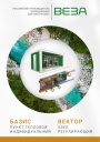
Каталог продукции Веза 2025 - Пункт тепловой индивидуальный БАЗИС, узел регулирующий ВЕКТОР. pdf, 8.85 Mb
Каталог индивидуальных тепловых пунктов БАЗИС, узлов регулирующих ВЕКТОР и блочных тепловых пунктов: назначение, схемы, комплектация, технические характеристики, габаритные размеры. -
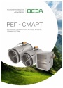
Каталог продукции Веза 2024 - Регуляторы переменного расхода воздуха РЕГ-СМАРТ для VAV-систем. pdf, 1.83 Mb
Каталог регуляторов переменного расхода воздуха РЕГ-СМАРТ для VAV-систем: назначение, конструкция, исполнения, технические характеристики, габаритные размеры, обозначение при заказе. -
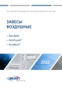
Каталог продукции Веза 2025 - Воздушные завесы. pdf, 4.97 Mb
Каталог воздушных завес Веза AeroWall, AeroGuard, AeroBlast: назначение, конструкция и исполнения, технические характеристики, габаритные размеры, подбор.
Новое в инструкциях
-

Полупромышленные канальные сплит-системы Shuft серии SFLC_D. pdf, 10.37 Mb
Модели: SFLC_D/in-18…60HN1_V2, SFLC_D/out-18…60HN1_V2. Руководство по эксплуатации: устройство, проводной пульт, монтаж, электрические схемы подключения, размеры, технические характеристики, устранение неисправностей, протоколы приёмки и тестового запуска, гарантийный талон. -

Полупромышленные напольно-потолочные сплит-системы Shuft серии SFLC_CF. pdf, 8.93 Mb
Модели: SFLC_CF/in-18…60HN1_V2, SFLC_CF/out-18…60HN1_V2. Руководство по эксплуатации: устройство, проводной пульт, монтаж, электрические схемы подключения, размеры, технические характеристики, устранение неисправностей, протоколы приёмки и тестового запуска, гарантийный талон. -

Мульти-сплит-системы Shuft серии FMI. pdf, 4.82 Mb
Модели: внутренние блоки SFMS/I-07…18 HB FMI/N8/IN/WHITE, наружные SFMO/I-14…42 FMI-2…5/N8/OUT. Руководство по эксплуатации: технические характеристики, управление кондиционером, монтаж, техническое обслуживание, поиск и устранение неисправностей, возможная комплектация блоков, гарантийный талон.