

Инструкция на Наружные блоки мини VRF-системы V4+ 8-10-12-14-16-18 (сервис мануалы)
Наружные блоки мини VRF-системы V4+ (R410a 380). Часть 3. Установка. Сервис мануал.
Смотрите также: Сервис мануал →
Загружаем документ…
Текст инструкции
-
1. Precautions
Ensure that all Local, National and International regulations are satisfied. Read this “PRECAUTIONS” carefully before Installation. The precautions described below include the important Items regarding safety. Observe them without fail. After the installation work, perform a trial…
-
Electrical work must be performed by a qualified electrician in accordance with the Installation Manual. Make sure the air conditioner uses an exclusive power supply. An insufficient power supply capacity or inappropriate installation may cause fire. Use the specified cables for wiring connect the…
-
3.2 Installation space (units: mm)
Since the gravity center of the unit is not at its physical center, so please be careful when lifting it with a sling. Never hold the inlet of the outdoor unit to prevent it from deforming. Do not touch the fan with hands or other objects. Do not lean it more than 45°, and do not lay it…
-
Outlet for power and connecting pipes
Reserve water outlet (Need to knock open) Reserve water outlet Water Outlet (With rubber stopper) While installing the outdoor unit, pay attention to the installation place and the drainage pattern; if it’s installed at the alpine zone, the frozen condensed water will block up the water outlet…
-
The first connecting method
Pipe Length (IDU to the nearest branch) L1 a A Maximum pipe equivalent length The first line Branch Pipe L2 Level difference bwtween IDU-IDU Level difference between ODU-ODU Outdoor unit Pipe Length (from the first branch to the furthest IDU) L3 B L4 C b L5 D c E e d f Indoor Unit The second…
-
Outdoor Unit(Take Model 14kW for example)
N1 (28) a L1 L2 A L3 The first line pipe branch intdoor Units B N2 (28) b L4 C N3 (28) c D L5 N4 (28) d e E f Pipe definition Pipe connecting position first branch of indoor unit. The main pipes of indoor unit The branch pipes of indoor unit N6 (22) Code The pipe between outdoor units to the Main…
-
Table 3: Main pipes selection (L1)
Total capacity of outdoor units (kW) When the equivalent length of all liquid and air pipes < 90m When the equivalent length of all liquid and air pipes ≥ 90m gas side liquid side The first line gas side liquid side (mm) (mm) branch pipe (mm) (mm) A<16 Φ15.9 Φ9.5 FQZHN-01C Φ19.1 Φ9.5 16≤A<23 Φ19.1…
-
Liquid Side Piping Diameter
Refrigerant to be Added Perimeter Piping Φ6.4 0.023kg Φ9.5 0.060kg Φ12.7 0.120kg Φ15.9 0.180kg Φ19.1 0.270kg Φ22.2 0.380kg Note: Additional refrigerant volume of divergent pipe is 0.1kg per item (Consider the liquid side of divergent pipe only). 4.8 Leak detection Use soap water or leak detector to…
-
5. Electric System
5.1 Wiring Diagrams and Field Wiring Wiring diagrams and field wiring please refer to “Wiring Diagrams and field wiring” of Part 2. 5.2 Description of Main Control Board of Outdoor unit Electric System 59
-
Dial codes definition
SW3 definition SW3 ON Obtain network address automatically OFF Obtain network address manually ON Revocation indoor unit network address OFF / 1 2 Explanation of main board No. Content No. 1 Port for inverter module voltage inspection Mutual inductor for compressor DC current Activation port of…
-
3) Fan speed: 0──OFF; 1~7──Speed increasing in turn
4) SW1: Forced cooling button. 5) SW2: Query button. 5.4 Description of Main Control Board of Indoor unit There are two shapes of main control board that used to all types of indoor unit matching with V4+ outdoor unit. Shape 1 Shape 2 Electric System 61
-
Dial codes definition
0/1 definition Means 0 Means 1 SW1 definition 1 means factory test mode 0 means default auto addressing mode 1 means DC fan is chosen 0 means AC fan is chosen 00 means DC fan static pressure is 0 (reserved) 01 means DC fan static pressure is 1 (reserved) 10 means DC fan static pressure is 2…
-
SW7 definition
Normal configuration R410a Full DC Inverter Mini VRF Last unit of the network J1 J2 definition Without jumper J1 for auto restart function reserved With jumper J1 for non-auto restart function Error code & indication Error code Lamp indication FE Time LED and run LED flash together H0 4 LED flash…
-
5.5 Electric Wiring Installations
5.5.1 Highlights of electrical installation 1) Please separately design the special power of indoor units and outdoor units. 2) The power adopts special circuit, and installs creepage protector and manual switch. 3) The indoor units’ power, creepage protector and manual switch connecting to the same…
-
4) The wiring with different voltage should not pass through the same wire tube
5) Total sectional area of wiring through wire tube shall not exceed 40% valid area of stuffing tube. 6) Fixing point of wire tube support shall follow the standard below: Normal diameter of wire tube Largest gap between fixed points of wire tube Mm Metal pipe Plastic pipe 15~20 1.5m 1m 25~32 2m…
-
5.5.5 Indoor unit power wiring selection
Note: 1) Set refrigerant piping system, signal wires between indoor unit, and that between outdoor units into one system. 2) Please do not put the signal wire and power wire in the same wire tube; keep distance between the two tubes. (Current capacity of power supply: less than 10A--300mm, less than…
-
6. Outdoor Unit Wiring
6.1The Specification of Power Table 6-1 Capacity 12kW-16kW 18kW 3 phase 3 phase 380-415V~ 50Hz 380-415V~ 50Hz 5-core X2.5 5-core X2.5 Circuit Breaker/Fuse (A) 25 32 Indoor unit/Outdoor unit Signal wire 2 (Weak electric signal) (mm ) 3-core shielded wire 3X0.75 3-core shielded wire 3X0.75 Outdoor…
-
Fig.6-2
CAUTION The reserved function is indicated in broken line table, users can select it when necessary. Indoor/Outdoor Unit Signal Wire Connect the wire according to their numbers. Wrong connection may cause malfunction. Wiring Connection Seal the wiring connection with the insulation material, or the…
-
6.2 Indoor Unit Wiring
Power Supply Table 6-2 Capacity (kW) 1.8~16 Phase indoor Unit power 1- phase Frequency and Voltage 220-240V~ 50Hz 2 Power Wiring(mm ) 3-core×1.0 Circuit Breaker (A) 16 2 Indoor unit/Outdoor unit Signal wire (Weak electric signal) (mm ) 3-core shielded wire 3X0.75 1. Signal wire is 3-core, polarized…
-
Indoor unit power supply wiring
Indoor Power Supply Circuit Breaker Manual swtich Wire Distribution Box Indoor Unit Fig.6-4 CAUTION 1. Refrigerant piping system, indoor unit-indoor unit connection signal wires and indoor unit-outdoor unit connection signal wire are in the same system. 2. When power cord is parallel with signal…
-
7.Test Running
Operate according to “key points for test running” on the electric control box cover. CAUTION Test running cannot start until the outdoor unit has been connected to the power for 12hours. Test running cannot start until all the valves are affirmed open. Never make the test running if the…
-
8.Precautions on Refrigerant Leakage
This air conditioner (A/C) adopts innocuous and nonflammable refrigerant. The locating room of the A/C should big enough that any refrigerant leakage is unable to reach critical thickness. So certain essential action can be taken on time. Refrigerant critical thickness: 0.44[kg/m 3] for R410A.…
Схемы, таблицы и рисунки — в просмотре документа выше. Клик по номеру страницы открывает её в просмотре.
Новое в каталогах
-
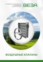
Каталог продукции Веза 2025 - Воздушные клапаны. pdf, 6.71 Mb
Каталог воздушных клапанов Веза: номенклатура, клапаны отсечные и регулирующие РЕГУЛЯР, РЕГУЛЯР-Л, РЕГЛАН, КЕДР и другие — конструкция, исполнения, приводы, технические характеристики, габаритные размеры. -
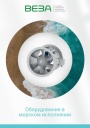
Каталог продукции Веза 2026 - Оборудование в морском исполнении. pdf, 7.62 Mb
Каталог вентиляционного и холодильного оборудования Веза в морском исполнении: радиальные и осевые вентиляторы, кондиционеры КОМПАС-БОВ, компрессорно-конденсаторные агрегаты КОМПАС-ККБ, шкафы управления КОМПАС-ШСАУ — технические характеристики и размеры. -
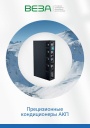
Каталог продукции Веза 2026 - Прецизионные кондиционеры АКП. pdf, 4.90 Mb
Каталог прецизионных кондиционеров АКП: назначение, исполнения, конструкция, технические характеристики, габаритные размеры, обозначение при заказе.
Новое в инструкциях
-

Водонагреватели косвенного нагрева Immergas серии Standart UBS . pdf, 676.07 Kb
Водонагреватели косвенного нагрева Immergas серии Standart UBS150/ Standart UBS 200/ Standart UBS 300 вертикальные из углеродистой стали толщиной 2мм с эмалевым покрытием емкостью 150/200/300 литров. Руководство по эксплуатации. -

Топочный автомат горения ОВЕН МГ1. pdf, 10.23 Mb
Руководство по эксплуатации топочного автомата горения МГ1 для автоматизации розжига и контроля пламени промышленных газовых надувных и атмосферных горелок (1- и 2-ступенчатых): технические характеристики, монтаж и схемы подключения, подключение датчика пламени и OwenCloud, принцип работы и диаграммы, режимы работы, настройка в Owen Configurator, защиты, список аварий, карта регистров сетевого интерфейса, выносная панель МГ1-ВП, техническое обслуживание. -

Электрические накопительные водонагреватели STOUT серии SEW . pdf, 3.22 Mb
Электрические настенные накопительные водонагреватели STOUT серии SEW-030L-01; SEW-050L-01; SEW-080L-01; SEW-100L-01 объемом 30-100 литров. Технический паспорт.