

Инструкция на Наружные водоохлаждаемые блоки VRF-системы V4+ (сервис мануалы)
Наружные блоки системы VRF V4+ с жидкостным охлаждением конденсатора (R410a DC Inverter V4 Plus W 50Hz). Часть 6. Система управления. Сервис мануал.
Смотрите также: Сервис мануал →
Загружаем документ…
Текст инструкции
-
1. Electric System
1.1 Wiring Diagrams and Field Wiring Wiring diagrams and field wiring please refer to ―6. Wiring Diagrams and field wiring‖ of ―Part 3 Specification & Performance‖ 1.2 Description of Main Control Board of Main unit Fig.1-1 Electric and Control System 105
-
■Explanation of main board
No Content 1 Reserve 2 Reserve 3 Air discharge temp. sensed port 2 of inverter compressor 4 Air discharge temp. sensed port 1 of inverter compressor 5 Power supply port in the Mid-adapted panel 6 Communication between indoor and main units, indoor unit network, main unit network and terminal of…
-
1.3 SW1 Query Instruction
No. Display content Note No. 1 Main unit address 0,1,2,3 14 2 Capacity of main unit 8,10,12 15 3 Qty. of modular main unit 4. Total capacity of main unit Total capacity requirement of indoor unit Total capacity requirement of master unit after correction Effective to master unit Capacity requirement…
-
1.4 Dial codes definition
Fig.1-2 S1 definition Starting time is set about 10 minutes Starting time is set about 12 minutes (Default the Factory Set) S3 definition Reserve S5 definition (For cooling & heating type) Heating priority mode (Default the Factory Set) Cooling priority mode Priority mode Only Respond the heating…
-
Reserve
NOTE: Please shut off the power when setting the switch Electric and Control System 109
-
1.5 Description of Main Control Board of Indoor unit
There are two shapes of main control board that used to all types of indoor unit matching with V4+ main unit. Shape 1 Shape 2 110 Electric and Control System
-
Dial codes definition
0/1 definition Means 0 Means 1 SW1 definition 1 means factory test mode 0 means default auto addressing mode 1 means DC fan is chosen 0 means AC fan is chosen 00 means DC fan static pressure is 0 (reserved) 01 means DC fan static pressure is 1 (reserved) 10 means DC fan static pressure is 2…
-
SW7 definition
Normal configuration Last unit of the network J1 J2 definition Without jumper J1 for auto restart With jumper J1 for non-auto restart function function Reserved Explanation of main board No. Content No. Content 1 Power input of transformer 12 Electric expansion valve drive port 2 Power output of…
-
13) Voltage discrepancy of power wire terminal (side of power transformer) and end voltage (side of unit) should be less than 2%. If its length could not be shortened, thicken the power wire. Voltage discrepancy between phases shall not pass 2% rated value and Current discrepancy between highest and…
-
It should turn on or shut down the unit at the same time, otherwise, the service life would affect seriously, even the unit may not turn on.) ■Please put the connective wiring system between indoor unit and main unit with refrigerant piping system together. ■It is suggested to use 3-core shielded…
-
Fig.1-9
Fig.1-10 ■Select the wire diameter Power wiring refer to the main wire (a) connecting to branch box and the wiring (b) between branch box and power facilities. Please select the wire diameter according to the following requirement. ·Diameter of main wire (a) Depends on the total horsepower of…
-
MCAC-VTSM-2012-09 ■Select the capacity of manual switch and fuse of the branch box ·See following table when without power facilities, depends on the main unit it connecting to. ·See table.1-5 below when there is power facility, depends on the total horsepower. Table.1-5 Total horsepower, capacity…
-
2. Control System
2.1 Control System Introduction 2.1.1 Connecting highlights of control line (RS-485 communication) 1. The control line should be shielded wire. Using other wiring shall create signal interference, thus leading to error operation. 2. The shielded nets at the two sides of shielded wires are either…
-
Note
1. The signal connecting line between main units, indoor and main units and indoor units has polarity. When connecting, be careful to prevent error connection. 2. Signal wire shall adopt three-core shielded wire with the dia. no less than 0.75m2. 3. The signal wire of indoor unit and main unit must…
-
Main unit
b. Star connection of signal wire ● Star connection of part signal wires Main unit ● Star connection of all signal wires Main unit c. Reverse connection of signal wire ● Main unit — indoor unit Main unit ● Indoor unit — indoor unit Main unit Caution: shielded layer should be connected to electrical…
-
indoor units which are in the same refrigerant system via the port X Y E of outdoor unit. Main unit will automatically distribute the address to indoor units without any manual setting. Remote controller can enquiry and modify every indoor unit address. The diagram below shows the connection of…
Схемы, таблицы и рисунки — в просмотре документа выше. Клик по номеру страницы открывает её в просмотре.
Новое в каталогах
-
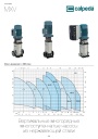
Каталог вертикальных многоступенчатых насосов Calpeda серий MXV, MXVL, MXV EI 2026. pdf, 7.05 Mb
Модели: MXV 25, 32, 40, 50, 65, 80, 100, MXVL 65, 80, MXV EI. Каталог серии: область применения, конструкция и материалы, рабочие характеристики и кривые, габаритные размеры и масса. -

Каталог осевых вентиляторов Shuft серии AXW. pdf, 4.05 Mb
Модели: AXW 4E–8DY с типоразмерами 200–910 в исполнениях S-G, S-T, B-T, B-P. Технический каталог модельного ряда: расшифровка обозначения, характеристики, схемы подключения, аэродинамические графики и габаритные чертежи. -
Каталог продукции Пульсар 2026 - Дренажные насосы. pdf, 3.91 Mb
Каталог продукции Пульсар 2026 - Дренажные насосы
Новое в инструкциях
-

Полупромышленные канальные сплит-системы Shuft серии SFLC_D. pdf, 10.37 Mb
Модели: SFLC_D/in-18…60HN1_V2, SFLC_D/out-18…60HN1_V2. Руководство по эксплуатации: устройство, проводной пульт, монтаж, электрические схемы подключения, размеры, технические характеристики, устранение неисправностей, протоколы приёмки и тестового запуска, гарантийный талон. -

Полупромышленные напольно-потолочные сплит-системы Shuft серии SFLC_CF. pdf, 8.93 Mb
Модели: SFLC_CF/in-18…60HN1_V2, SFLC_CF/out-18…60HN1_V2. Руководство по эксплуатации: устройство, проводной пульт, монтаж, электрические схемы подключения, размеры, технические характеристики, устранение неисправностей, протоколы приёмки и тестового запуска, гарантийный талон. -

Мульти-сплит-системы Shuft серии FMI. pdf, 4.82 Mb
Модели: внутренние блоки SFMS/I-07…18 HB FMI/N8/IN/WHITE, наружные SFMO/I-14…42 FMI-2…5/N8/OUT. Руководство по эксплуатации: технические характеристики, управление кондиционером, монтаж, техническое обслуживание, поиск и устранение неисправностей, возможная комплектация блоков, гарантийный талон.