

Инструкция на VRF-системы V4 (сервис мануалы)
Устранение неисправностей VRF-системы. Сервис мануал.
Смотрите также: Коды ошибок CCM03 →
Загружаем документ…
Текст инструкции
-
VRF system Trouble shooting
-
Content
Outdoor Error Code Explanation Indoor Error Code Explanation System trouble analysis
-
Midea VRF system has self trouble analysis function,
the service people can be benefited a lot: When system in error status, the outdoor unit or indoor unit can display the error code: In the indoor PCB, there’s LED for error code display; In the outdoor unit display board, it will display the error code. E1
-
70 23: when in standby mode, it display the quantity of indoor units in the system; 70: when outdoor unit is running, For DC Inverter System, It display the frequency of inverter compressor(70HZ); For Digital Scroll System It display the ratio of power output (70%) dF dF: when in defrost mode, it…
-
d0
-
No
Display 1 E0 Communication error between outdoor units Only slave unit display 2 E1 Phase protection All the outdoor units display 3 E2 Communication error between indoor unit and master unit All the outdoor units display 4 E4 Outdoor temperature sensor error All the outdoor units display 5 E5…
-
No
Display Malfunction or Protection Remark 14 P1 Hi-pressure protection All the outdoor units display 15 P2 Low-pressure protection All the outdoor units display 16 P3 Inverter or digital compressor current Protection All the outdoor units display 17 P4 Compressor discharge temperature protection All…
-
E0: Communication error between outdoor units
More than 3 is forbidden Check address code setting of outdoor units Yes Reset address No H1 to H1, H2 to H2? Open or short circuit? Check the connection of communication wire between outdoor units: Yes Reconnect or change communication wire. Yes Reinstall or replace the chip Shielding wire? No…
-
E1: Phase-sequence reverse or lose
Must be same with compressor requirement Check Phase-sequence (Auto-check is only valid when first powered on.) Yes Change sequence of any two phase line No power wire is not well touched with the terminals Check if the power supply lose phase Yes Fix the wire with terminal No Correct direction?…
-
Three-phase power protector
The bad power supply may cause the compressor badly damaged by frequent start/stop, over/under voltage, over current, reverse roll, etc.
-
From Power Supply
To low pressure switch Connect to the transferring cable of lower pressure switch, i.e. the original port of low pressure switch. To Port 95, 98 The logic is: Serial in the protector output signal to the Low pressure switch, When phase sequence error or lack of phase, the Outdoor PCB will display E1…
-
E2: Communication Error
between Outdoor Unit and Indoor Units Short or Open circuit? Address code is repeated All the indoor units are powered on? Hand in hand connection? Too closed to the strong power? Too many lamps? Power transforms? The wire is too long? Check communication wire between indoor and outdoor unit…
-
E4: Outdoor ambient temperature sensor(T4) error
Check the connection between the sensor and PCB. Error well Connected the sensor with the PCB OK Open or short circuit Temp. (℃) Resistor value (KΩ ) 6.4 Check if sensor is damaged OK Check chip or outdoor PCB Error Change a new sensor
-
E9: Voltage too high or low,
Too high or too low? Compressor is short circuit? Fan motor is short circuit? Check the voltage of power supply Error use stable power supply OK Check the electric part of strong power IPM output abnormal? OK Check chip or outdoor PCB Error Replace the broken part
-
H2: Error of reduction in the number of outdoor units
The signal wire between outdoor unit is loosed during running? Check signal wire between outdoor units Error Well connected the signal wire OK The power wire is loosed? Check the power supply for each outdoor unit OK Check chip or outdoor PCB Error Well connected the power wire
-
Charge additional refrigerant
correctly? Refrigerant leakage? Too close between outdoor units? Outdoor fan is broken? Short circuit between discharge air and suction air? Too dirty of outdoor coil? Too many indoor units? P0, P4: High discharge temp.(P0 only for inverter compressor Lack of refrigerant Error OK Error High ambient…
-
P1: High-pressure Protection
Too close between outdoor units? Outdoor fan is broken? Short circuit between discharge air and suction air? Too dirty of outdoor coil? Heat exchange of outdoor unit is not good Error Check and repair one by one Error Remove the dirty; Open the valve Error Discharge refrigerant, vacuum, recharge…
-
P2: Low-pressure Protection
Charge additional refrigerant correctly? Refrigerant leakage? Gas pipe is blocked? Gas valve is not opened Lack refrigerant Error Repair the leakage & Charge refrigerant; Error Remove the dirty; Open the valve OK High temp. of discharge and suction, low operation current, low pressure is low? Check…
-
compressor Heat exchange of outdoor unit is not good OK Check the liquid side of system OK There is Air or N2 in the system OK Short circuit of strong power part? Compressor malfunction? The normal resistance between any two terminals of compressor is 1~3Ω Too much refrigerant in the system OK…
-
P5: High temp. protection of outdoor condensor
Check the connection, sensor and terminal Error Well connected the wire; Replace the sensor or terminal OK Check if the cooling load is too big OK Heat exchange of outdoor unit is not good OK Check chip or PCB There is Air or N2 in the system ok OK Check the liquid side of system, jam? ok Check…
-
P6: Inverter module protection
Heat exchange is not good? Ambient temp. is too high? High temp. Error Improve the heat exchange; block the sunshine. OK Compressor malfunction? Big current Error Short circuit happens to strong power Check strong power part & compressor OK Use this module in another outdoor unit to check Module is…
-
All lamps off: indoor unit is in standby mode
-
Timer lamp flashes
Communication Error between Outdoor Unit and Indoor Units: See the solution in E2 of outdoor unit
-
Defrost lamp flash
Mode conflict : For the Inverter Smart system, cooling or heating can be not realized by the same system at the same time. Heating mode has priority: Rules: Outdoor unit is running in cooling mode, when received heating requirement, outdoor unit change to heating mode and the indoor units which…
-
Operation lamp flashes
Room temp. sensor T1 Indoor coil middle temp. sensor T2 Indoor coil outlet temp. sensor T2B Indoor temp. sensor abnormal Check the connection port between sensor and PCB is loosed or not? Error Well connected the sensor and PCB No Sensor is open circuit? Sensor is short circuit Check the sensor is…
-
Check the power
is failure? If the drainage pipe is blocked? The lift height of drainage pipe is more than the limitation ? Alarm lamp flashes Revise the mistake Condensate Water lever is higher Check the connection between switch and PCB is loosed or not? Error Well connected the switch and PCB No Check the…
-
Poor performance
wrong selection of refrigerant pipe, indoor EXV or branch joint, the refrigerant distribution among the indoor units is quite imbalance; 1.Low designed load 2.Long refrigerant pipe and big height difference 3.The match ratio is more than 130% 1.Leakage in the system; 2.Additional refrigerant is not…
-
How to Check indoor capacity code Quickly
Address code Capacity (x 100W) Horsepower (HP) 0.8 1.0 1.2 1.6 2.0 2.5 3.0 3.2 4.0 5.0 In the below example: Operation and Alarm lamp is constant-on. The capacity code = 8+1=9 Continue pressing the “manual” button” of indoor unit for 10s, the capacity code of this indoor unit will display. 1
-
How to set indoor capacity code
-
The suction pipe Frost
Outdoor ambient temp. is low or high? Frost volume is much or little? Check ambient temp. and frost volume Error Find the root cause Error Clean the indoor unit; Fix the broken part OK Indoor EXV jammed? Indoor fan doesn’t run? Check low pressure Filter or coil of indoor unit is too dirty? OK When…
Схемы, таблицы и рисунки — в просмотре документа выше. Клик по номеру страницы открывает её в просмотре.
Новое в каталогах
-
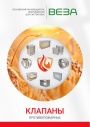
Каталог продукции Веза - Клапаны противопожарные. pdf, 77.84 Mb
Каталог противопожарных клапанов Веза (КПУ и др.): назначение, конструкция и исполнения, приводы, технические характеристики, габаритные размеры, схемы электрические подключения. -
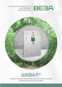
Каталог продукции Веза 2026 - Шкафы управления для систем приточно-вытяжной противодымной вентиляции ШКВАЛ. pdf, 6.57 Mb
Каталог шкафов управления ППУ ШКВАЛ для систем приточно-вытяжной противодымной вентиляции: назначение и типы, номенклатура, конструкция, габаритные размеры и масса, маркировка, схемы внешних соединений, комплект поставки. -

Каталог продукции Веза - Противопожарный вентилятор ОСА-ЭВО-ДУВ. pdf, 9.16 Mb
Каталог противопожарных осевых вентиляторов ОСА-ЭВО-ДУВ: назначение, конструкция и исполнения, аэродинамические и технические характеристики, габаритные размеры, обозначение при заказе.
Новое в инструкциях
-

Водонагреватели косвенного нагрева Immergas серии Standart UBS . pdf, 676.07 Kb
Водонагреватели косвенного нагрева Immergas серии Standart UBS150/ Standart UBS 200/ Standart UBS 300 вертикальные из углеродистой стали толщиной 2мм с эмалевым покрытием емкостью 150/200/300 литров. Руководство по эксплуатации. -

Топочный автомат горения ОВЕН МГ1. pdf, 10.23 Mb
Руководство по эксплуатации топочного автомата горения МГ1 для автоматизации розжига и контроля пламени промышленных газовых надувных и атмосферных горелок (1- и 2-ступенчатых): технические характеристики, монтаж и схемы подключения, подключение датчика пламени и OwenCloud, принцип работы и диаграммы, режимы работы, настройка в Owen Configurator, защиты, список аварий, карта регистров сетевого интерфейса, выносная панель МГ1-ВП, техническое обслуживание. -

Электрические накопительные водонагреватели STOUT серии SEW . pdf, 3.22 Mb
Электрические настенные накопительные водонагреватели STOUT серии SEW-030L-01; SEW-050L-01; SEW-080L-01; SEW-100L-01 объемом 30-100 литров. Технический паспорт.