

Инструкция на Чиллеры Clivet серии WSAT...
Чиллеры Clivet серии WSAT-ЕЕ 17-21-25-31-41-51-61-71-81-91-101-121-131-151 с водяным охлаждением для наружной установки. Инструкция по монтажу и эксплуатации.
Смотрите также: Инструкция по монтажу и эксплуатации →
Загружаем документ…
Текст инструкции
-
WSAT-EE
17-21-25-31-41-51-6171-81-91-101-121-131-151 ELFO ENERGY COMPACT AIR COOLED WATER CHILLER FOR OUTDOOR INSTALLATION Installation and Use Manual M02Q40C8-00 26/05/08
-
UNIT IDENTIFICATION
SERIAL NUMBER LABEL The units are identified by the serial number label shown here. The label lists the type of unit (series and size), serial number, year of manufacture, number of electrical diagram, main technical data, logo and address of the manufacturer. The label is placed on the unit…
-
INSTRUCTIONS FOR THE USER
• This is a partial sintex of the information provided in the manual; carefully read this manual • Carefully read this manual. Keep it with the electrical diagram. Make it available to technicians for servicing. • Ask the installer for training on start-up, shutdown, changing set points, placing in…
-
REFRIGERANT CIRCUIT ALARM
Inlet probe Outlet probe Radiant panel water probe Coil/flow probe External probe Pressure 1 probe Water reset inlet External relative humidity probe Phase monitor Electric heater output probe HP LP CCMP/VENT HP1 Pre-Alarm BP1 Pre-Alarm serial faulty alarm serial faulty alarm Flow pump System…
-
GENERAL WARNINGS
MANUAL PURPOSE This manual has been designed to enable the unit to be installed, started up and maintained correctly. MANUAL INSTRUCTIONS It is essential to observe these instructions. The manufacturer declines all liability for any damage that may be caused whether directly or indirectly to persons…
-
RESIDUAL RISKS
GENERAL This section lists some of the more common situations which, being beyond the control of the manufacturer, could be a source of risk to persons or property. DANGER AREA The figure below highlights the area in which only authorised personnel may operate. • External danger zone, identified by…
-
Contact with parts that could become live when the unit is
started up can result in electric shock, burns or death by electrocution. When there is no need for circuits to be powered up, set the isolating switch on the power line to the OFF position, padlock it and post a warning sign. MOVING PARTS Contact with the fan rotors can cause injury. Before…
-
Chemical -physical
properties. Relative density, gas (air=1) Heavier than air. Solubility in water (mg/l). Not known, but probably very low. Aspect. Colourless liquefied gas. Smell. Simile to ether. Point of ignition. Don’t ignite. Stability and reactivity. Stability and reactivity. No decomposition if used following…
-
RECEPTION
INSPECTION UPON RECEPTION Check on arrival that the unit has not suffered damage during transit and that it is complete in every part as specified in the order. In the event of visible damage/deficiencies being discovered, make a note immediately on the delivery document with the comment…
-
POSITIONING
GENERAL For installing air-conditioning systems, it is necessary to consider the following: • the technical spaces necessary for the machine and system • the place where the machine will be installed • the transport of thermal carrier fluids and relevant connections to the unit: o water o air o…
-
Install the unit raised off the ground and on a sturdy base
Consider the maximum depth that snowfall might reach. ! ! 2A ! Tree ! A Consider clearances and direction of expelled air. Keep the coil clean. Avoid zones with leaves / dirt / corrosives. 1. elastic joint 2. floating floor 3. soundproofing Prevent the transmission of vibrations. ! Provide…
-
WATER CONNECTIONS
GENERAL Piping must be designed with the least possible number of bends and head variations. If the pressure chute of the installation is above the useful prevalence of the pump, the water delivery capacity is reduced as well as, as a consequence, the thermal exchange and the yield. INTERCEPTING…
-
DIAGRAM OF RECOMMENDED USE SIDE CONNECTION
Depending on the type of machine and the selected setup, some components may be integrated into the unit. The accumulation tank is necessary in the event of the following: • the water in the system is very low • the unit will not be used in a private house (in an industrial process or other) P 1. 2.…
-
ELECTRICAL CONNECTION
the unit; the electrical data shown in the technical chart refer to standard units. In the event of differences between the data of the registration plate and the data shown in this manual, as well as in the technical chart, please refer to the DATA SHOWN IN THE REGISTRATION PLATE. The protection…
-
CONNECTION TO THE MAINS
1. Make sure that the sectioning device at the beginning of the unit’s power line is opened, locked and equipped with a signal. 2. Open the general line disconnecting switch (if present) 3. Verify that the net is in conformity with the data shown in the registration plate placed on the electrical…
-
FUNCTIONAL CONNECTIONS
FOR ALL THE CONNECTIONS MAKE REFERENCE TO THE ELECTRICAL PANEL SUPPLIED WITH UNIT Use voltage-free remote control devices that are suitable to commutate very low loads (12V, 10mA) Few inputs must be activated by configuration parameters whose access is reserved to authorized assistance centres (in…
-
The water set point at the radiant panels can be managed in three ways
1. the valve is managed to maintain the outlet temperature at par 192 value. 2. calculated automatically in function of the external air temperature; two set are calculated (HEAT. / COOL.) that become actives on the basis of the unit operating mode. This configuration is obtained setting par 190=1…
-
UNIT INTERFACE VIA RS 485 Below the indications for the serial connection ; refer anyway to the CLIVET “RS 485 NETWORKS – GUIDELINES” document and ask for the COMMUNICATION PROTOCOL about the COMPACT electronics - The total length of each single serial line, don’t have to be over 1000 metres The…
-
START-UP
ALL THE EQUIPMENT MUST BE COMMISSIONED BY AUTHORISED SERVICE CENTRES. THIS SERVICE IS LIMITED TO START-UP OF THE UNIT ONLY AND NOT THE CONNECTIONS OR INSTALLATION OF THE SYSTEM. ONLY QUALIFIED TECHNICIANS MUST PERFORM THE FOLLOWING OPERATIONS. PRELIMINARY CHECKS Before checking, please verify the…
-
VERIFY TENSIONS – ABSORPTIONS
EVAPORATOR WATER FLOW RATE Check that the temperatures of the fluids are included in the WORKING LIMITS. Check that the difference between the temperature of exchanger return and supply water corresponds to power according to this formula: If the controls of the previous paragraphs are positive, it…
-
CONTROL
The HEATING mode functions are active only on HEAT PUMP unit version . In ONLY COOL units, the relative parameters are VISIBLE but NOT ACTIVE , for example the winter setpoint. OPERING MODES ON – OFF Unit can be switched on and off by: • keypad • remote switch (see ELECTRICAL CONNECTIONS paragraph)…
-
COMPENSATED compressor activation point
offset by compensation non compensated compressor activation point o e O s ACTUAL set point • The compensation on the DURATION is useful when the installation water content is limited. • The compensation on the CHARGE is useful if the variable charge is present. For the enabling and the…
-
MAINTENANCE
This way, the plant can be kept within the operating limits even when the unit is OFF or on STANDBY, for example during the weekend or the night-time. Periodically the system activates the circulation pump, measures the water temperature and activates the compressor, if required, to take the water…
-
SELECTING OPERATING TEMPERATURE
COMFORT: to select the COMFORT temperature for the current operating mode, press the COMFORT key. The set point is only displayed on the machine. When this mode is activated, the led to the left of the key lights up and remains alight. ECO: to select the ECONOMIC temperature for the current…
-
VISIBLE STATUS FROM REMOTE KEYBOARD OR SERVICE KEYBOARD
INDICE DESCRIPTION Current Set Point Temperature drop in degrees centigrade given by the compressor including compensations, if any Resource activation timer When this value reaches the value fixed at the next status (TimeScan), the thermal regulator will compare the input temperature with the set…
-
ALARMS
BEFORE RESETTING THE ALARM, IDENTIFY AND ELIMINATE THE CAUSE OF ITS ACTIVATION. REPEATED RESETS CAN CAUSE IRREVERSIBLE DAMAGES. The ALARMS show a potentially dangerous situation for machine safety. Before resetting the alarm, discover and remove the cause: repeated resetting could cause irreversible…
-
ROUTINE MAINTENANCE
BEFORE UNDERTAKING ANY SORT OF MAINTENANCE OR CLEANING, DISCONNECT THE ELECTRICAL POWER SUPPLY TO THE UNIT, AND ENSURE THAT OTHER PEOPLE CANNOT RE-CONNECT IT . All equipment is subjected to wear out. The maintenance makes : 1. keeps the unit efficiency 2. the components last longer 3. keeps their…
-
MAINTENANCE INSPECTIONS
Foresee inspection assistance carried out by authorized centers or by qualified personnel. The inspections should be carried out at least: • Every year for only the cooling units • Every six months for the cooling and warming units The frequency, however, depends on the use: in the event of frequent…
-
REFRIGERANT TABLES
THIS SECTION IS DEVOTED ONLY TO QUALIFIED TECHNICIANS THAT KNOW THE FOLLOWING: • THE OPERATIONAL PRINCIPLES OF THE REFRIGERATING CIRCUIT OPERATION • THE MODES OF DETECTING TEMPERATURE AND PRESSURE • THE RISKS RELEVANT TO THESE OPERATIONS The data of the tables allow the testing of the refrigerating…
-
TROUBLESHOOTING
THE OPERATIONS MUST BE CARRIED OUT BY TECHNICAL QUALIFIED PERSONNEL HAVING THE REQUISITES UNDER LAW REQUISITES AND IN CONFORMITY WITH THE SAFETY REGULATIONS IN FORCE. THE INTERVENTIONS WITHIN THE WARRANTY PERIOD WILL BE CARRIED OUT BY AUTHORIZED SERVICE CENTERS. BEFORE RESETTING AN ALARM, IDENTIFY…
-
COMPRESSOR PROTECTION
1. Identify the part on the wiring diagram 2. Loose electric contacts/terminals, leads broken 3. electrical windings interrupted 4. Vacuum power voltage below the limits 5. power contactors / contacts defective 6. start-up power voltage lower than the limits 7. electrical absorption high /…
-
DECOMMISSIONING OF THE UNIT
DISCONNECTING THE UNIT DISMANTLING AND DISPOSAL The units must be disconnected by authorised personnel, who before proceeding must first read the Residual Risks section in this manual. THE UNIT MUST ALWAYS BE SENT TO AUTHORISED CENTRES FOR DISMANTLING AND DISPOSAL. Before disconnecting the unit, the…
-
TECHNICAL DATA
-
DIMENSIONS
Size 17-21-25 (1) COMPRESSOR (2) EXTERNAL EXCHANGER (3) INTERNAL EXCHANGER (4) ELECTRICAL PANEL (5) WATER INLET 1" GAS (6) WATER OUTLET 1" GAS (7) FAN (8) PUMP (9) WATER SIDE SAFETY VALVE (10) POWER INPUT (11) EXPANSION VESSEL (12) CLEARANCE ACCESS RECOMMENDED ("G") BARYCENTRE M N O P (12) W1 W2 W3…
-
Size 31
(1) COMPRESSOR (2) EXTERNAL EXCHANGER (3) INTERNAL EXCHANGER (4) ELECTRICAL PANEL (5) WATER OUTLET 1" GAS (6) WATER INLET 1" GAS (7) FAN (8) PUMP (9) WATER SIDE SAFETY VALVE (10) POWER INPUT (11) EXPANSION VESSEL (12) CLEARANCE ACCESS RECOMMENDED ("G") BARYCENTRE (12) 150 157 P (12) 500 O (12) 100 1…
-
Size 41-51
(1) COMPRESSOR (2) EXTERNAL EXCHANGER (3) INTERNAL EXCHANGER (4) ELECTRICAL PANEL (5) WATER OUTLET 1" GAS (6) WATER INLET 1" GAS (7) FAN (8) PUMP (9) WATER SIDE SAFETY VALVE (10) POWER INPUT (11) EXPANSION VESSEL (12) CLEARANCE ACCESS RECOMMENDED ("G") BARYCENTRE 7 8 1244 (12) 150 M N O P W1 P (12)…
-
Size 61-71
411 1040 2 (1) COMPRESSOR (2) ELECTRICAL PANEL (3) INTERNAL EXCHANGER (4) EXTERNAL EXCHANGER (5) HELICAL FANS (6) PUMP (7) EXPANSION VESSEL (8) WATER OUTLET (STANDARD UNIT) (9) WATER INLET (STANDARD UNIT) (10) POWER INPUT (11) CLEARANCE ACCESS RECOMMENDED (12) LIFTING HOLES ("G") BARYCENTRE M 5 W3 7…
-
Size 81-91-101-121
-
Size 131-151
684 1711 1476 8 (1) COMPRESSOR (2) ELECTRICAL PANEL (3) INTERNAL EXCHANGER (4) EXTERNAL EXCHANGER (5) HELICAL FANS (6) PUMP (7) EXPANSION VESSEL (8) WATER OUTLET (STANDARD UNIT) (9) WATER INLET (STANDARD UNIT) (10) POWER INPUT (11) CLEARANCE ACCESS RECOMMENDED (12) LIFTING HOLES ("G") BARYCENTRE…
-
TECHNICAL DATA
Size COOLING Cooling capacity 1 kW Compressor power input 1 kW Total power input 2 kW EER 3 ESEER COMPRESSOR Type of compressors 7 No. of Compressors Nr Compressor RPM 6 rpm Std Capacity control steps Nr Refrigerant charge (C1) 8 kg Refrigerant circuits Nr INTERNAL EXCHANGER Type of internal…
-
DIMENSIONS
Length Depth Height Packing volume STANDARD UNIT WEIGHTS Shipping weight Operating weight mm mm mm m3 0.2 0.2 0.2 0.4 800 300 1244 0.5 800 300 1244 0.5 1087 411 1175 0.7 1087 411 1175 0.7 1373 555 1225 0.7 1373 555 1225 0.7 1373 555 1225 1.1 1373 555 1225 1.1 1710 684 1477 2.1 1710 684 1477 2.1 kg…
-
CORRECTION FACTOR FOR ANTIFREEZE SOLUTIONS
% ethylene glycol by weight 5% 10% 15% 20% 25% 30% 35% 40% Freezing temperature °C -2.0 -3.9 -6.5 -8.9 -11.8 -15.6 -19.0 -23.4 Safety temperature °C 3.0 1.0 -1.0 -4.0 -6.0 -10.0 -14.0 -19.0 Cooling Capacity Factor Nr 0.995 0.990 0.985 0.981 0.977 0.974 0.971 0.968 Compressor input Factor Nr 0.997…
-
INTERNAL EXCHANGER PRESSURE DROP
EXCHANGER PRESSURE DROP LIMIT. WARNING: DON'T USE OVER THIS LIMIT 71-81 DP (kPa) DP (kPa) 0,1 0,2 0,3 0,4 0,5 0,6 0,3 0,7 0,4 0,5 0,6 0,7 0,8 0,9 1,0 1,1 1,2 1,3 1,4 1,5 1,6 1,7 1,8 1,9 2,0 Q (l/s) Q (l/s) EXCHAMGER PRESSURE DROP LIMIT. WARNING: DON'T USE BELOW THIS LIMIT. UNIT WITHOUT HYDRONIC…
-
CLIVET SPA
Feltre (BL) ITALY Tel. + 39 0439 3131 Fax + 39 0439 313300 info@clivet.it CLIVET ESPAÑA S.A. Madrid - SPAIN Tel. + 34 91 6658280 Fax + 34 91 6657806 info@clivet.es CLIVET UK LTD Fareham (Hampshire) U.K. Tel. + 44 (0) 1489 572238 Fax + 44 (0) 1489 573033 info@clivet-uk.co.uk CLIVET NEDERLAND B.V.…
Схемы, таблицы и рисунки — в просмотре документа выше. Клик по номеру страницы открывает её в просмотре.
Новое в каталогах
-
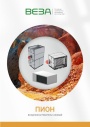
Каталог продукции Веза 2026 - Воздухонагреватели газовые ПИОН. pdf, 6.55 Mb
Каталог газовых воздухонагревателей ПИОН: назначение, конструкция и исполнения, технические характеристики, габаритные размеры, обозначение при заказе. -
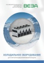
Каталог продукции Веза 2026 - Холодильное оборудование для систем кондиционирования воздуха. pdf, 4.97 Mb
Каталог холодильного оборудования Веза для систем кондиционирования: чиллеры, компрессорно-конденсаторные блоки, фанкойлы и другое оборудование — технические характеристики, габаритные размеры, обозначение при заказе. -

Каталог продукции Веза 2025 - Люки и зенитные фонари различного назначения. pdf, 8.45 Mb
Каталог люков дымоудаления и зенитных фонарей Веза различного назначения: конструкция и исполнения, приводы и автоматика, технические характеристики, габаритные размеры.
Новое в инструкциях
-
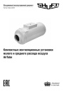
Компактные приточные установки Shuft серии AirTube. pdf, 350.53 Kb
Модели: AirTube 160, 200, 250, 315. Паспорт (объединённый эксплуатационный документ): описание устройства, монтаж, подключение электропитания, схемы электрических соединений, обслуживание, поиск и устранение неисправностей, гарантия, технические данные. -
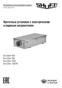
Приточные установки Shuft серии Eco-Slim. pdf, 8.64 Mb
Модели: Eco-Slim 350, 700, 1100, 1100 W. Паспорт (объединённый эксплуатационный документ) установок с электрическим и водяным нагревателем: технические характеристики, монтаж, схема электрического подключения, обслуживание, пульт управления «Oazis», неисправности. -
Канальные фанкойлы Shuft серии SFF. pdf, 1.91 Mb
Модели: SFF-200G50 … SFF-1400G50. Инструкция по эксплуатации средненапорных канальных фанкойлов: внешние виды и размеры, технические характеристики, монтаж, электропроводка, техническое обслуживание, устранение неисправностей.