

Инструкция на Промышленные кондиционеры канального типа Midea серии MHB-76-96CRN1, MHB-76-96HWN1
Промышленные кондиционеры канального типа Midea высоконапорные серии MHB-76CRN1 / MOV-76CN1-C, MHB-96CRN1 / MOV-96CN1-C, MHB-76HWN1/MOV-76HN1-R, MHB-96HWN1/MOV-96HN1-R. Руководство по техническому обслуживанию.
Загружаем документ…
Текст инструкции
-
Middle Static Pressure Duct unit
High Static Pressure Duct unit Service Manual 2013 MTA-76CRN1 / MOV-76CN1-C MTA-96CRN1 / MOV-96CN1-C MTA-120CRN1 / MOV-120CN1-C MTA-150CRN1 / 2* MOV-76CN1-C MTA-76HRN1 / MOV-76HN1-C MTA-96HRN1 / MOV-96HN1-C MTA-120HRN1 / MOV-120HN1-C [Введите текст] MHB-76CRN1 / MOV-76CN1-C MHB-96CRN1 / MOV-96CN1-C…
-
Part 1
DM13-01.01.16en General Information 1. Model Names of Indoor/Outdoor Units 3 2. External Appearance 4 3. Nomenclature 5 2 Service manual
-
1. Model Names of Indoor/Outdoor Units
1.1 Model Names of Units with Cooling only: Type Mid-static pressure duct type High-static pressure duct type Indoor unit Power Model supply MTA-76CRN1 MTA-96CRN1 MOV-76CN1-C MOV-96CN1-C MTA-120CRN1 MOV-120CN1-C MTA-150CRN1 MHB-76CRN1 220~240V-1 Ph-50Hz MHB-96CRN1 Outdoor unit Model MOV-76CN1-C *2…
-
2. External Appearance
-
3. Nomenclature
3.1 Indoor unit: M T A – 76 C R N1 None:R22;N1:R410a R:Remote Controller Function Code: C: Cooling H: Cooling and Heating Cooling Capacity (*76 kBtu/h) Product Series A: 1st time design B: 2nd time design Indoor Units T: Duct type H: High static pressure Midea 3.2 Outdoor unit: M O V 76 C N1 - C…
-
1. Features
1. Nested in the ceiling, space-saving and noble. 2. High capacity of cooling/heating, efficient, and energy-saving. 3. The air outlet is laid out according to you desire. 4. Economic and convenient installation 1) Several diffusers branch off from an indoor unit, adjusting the room temperature…
-
2. Specifications
Model MTA-76CRN1 MTA-76HRN1 MTA-96HRN1 Power supply - Temp. setting range ℃ ≥17 ≤30 ≥17 ≤30 Rated input power W 11700 11700 14400 14400 Rated current A 19.3 19.3 23.7 23.7 Btu/h 76000 76000 96000 96000 W 22000 22000 28000 28000 Input W 7500 7500 9600 9600 EER W/W 2.93 2.93 2.92 2.92 Btu/h / 78000 /…
-
Model
MTA-120CRN1 MTA-120HRN1 MTA-150CRN1 MTA-150CRN1 Power supply - 220~240V-1Ph-50Hz 220~240V-1Ph-50Hz Temp. setting range ℃ ≥17 ≤30 ≥17 ≤30 Rated input power W 17300 17300 21200 21200 Rated current A 28.6 28.6 35 35 Btu/h 120000 120000 150000 150000 W 35000 35000 44000 44000 Input W 12000 12000 15100…
-
Model
MHB-76CRN1 MHB-76HRN1 MHB-96CRN1 MHB-96HRN1 Power supply - 220~240V-1Ph-50Hz 220~240V-1Ph-50Hz Temp. setting range ℃ ≥17 ≤30 ≥17 ≤30 Rated input power W 11700 11700 14400 14400 Rated current A 19.3 19.3 23.7 23.7 Btu/h 76000 76000 96000 96000 W 22000 22000 28000 28000 Input power W 7500 7500 9600…
-
3. Dimensions
-
D
-
≥500mm
4. Service Space H ≥600mm Electric control box Inspection hole Inspection hole Top view Side view Canvas adapter Muffle Air outlet Muffle Air inlet Inspection hole Air filter Air duct system Service manual 13
-
5. Refrigerant cycle diagram
5.1 Cooling only: MTA-76CRN1, MTA-96CRN1, MTA-120CR N1, MTA-150CR N1 MHB-76CRN1, MHB-96CRN1 Outdoor heat-exchanger Cooling HP Switch Stop valve Stop valve T3 Indoor unit Check valve Discharge temp. sensor LP Switch Compressor Indoor heat-exchanger Liquid-gas seperator T2 T4 5.2 Cooling and heating…
-
6. Wiring Diagrams
6.1 MTA-76CRN1, MTA-96CRN1, MHB-76CRN1, MHB-96CRN1 TO WIRE CONTROLLER CN11 CN10 MAIN CONTROL BOARD WHITE WHITE BROWN BROWN BROWN BROWN HIGH SLOW BLACK WHITE N-LINE BLUE YELLOW E BL U E B LU BLACK BLACK YELLOW BROWN GREEN RL3 CN1 BROWN CN2 RL2 RED RED BLUE RED BLUE RED BLUE CN3 RL1 BROWN CN7 RED CN20…
-
MTA-120CRN1, MTA-150CRN1
TO WIRE CONTROLLER CN11 CN10 MAIN CONTROL BOARD BROWN BROWN BROWN SLOW BLACK RED BLUE BLUE WHITE LOW YELLOW BLUE BLUE HIGH RED YELLOW BROWN GREEN RED BLUE RED BLACK WHITE YELLOW WHITE BROWN CN1 BLUE RED RL3 BLACK RED RL2 RED CN2 BROWN CN3 BROWN CN7 RED CN20 RL1 BLUE CN8 CN15 RED Y/G WHITE (GRAY)…
-
6.2 MTA-76HRN1, MTA-96HRN1, MHB-76HRN1, MHB-96HRN1
TO WIRE CONTROLLER CN11 CN10 MAIN CONTROL BOARD RED BLUE WHITE HIGH BROWN BROWN BROWN SLOW BLACK YELLOW WHITE N-LINE BLACK RED LOW BLUE Y/G WHITE (GRAY) WHITE RED BLACK YELLOW RED BLACK BLUE RED YELLOW Y/G BLUE YELLOW BLACK UE BL E U L B RED YELLOW BLACK BROWN GREEN RED BLUE RL3 CN1 WHITE RED BLUE…
-
MTA-120HRN1
TO WIRE CONTROLLER CN11 CN10 MAIN CONTROL BOARD BROWN BROWN BROWN BLUE WHITE BLACK RED BLUE BLUE SLOW LOW YELLOW BLUE HIGH RED YELLOW BROWN GREEN RED BLUE RED BLACK WHITE YELLOW WHITE BROWN CN1 BLUE RED RL3 BLACK RED RL2 RED CN2 BROWN CN3 BROWN CN7 RED CN20 RL1 BLUE CN8 CN15 RED Y/G WHITE (GRAY)…
-
7. Capacity Table
7.1 Cooling: 7.1.1 MTA-76CRN1 Gross Cooling Capacity(kW) Outdoor DB(°C) 29.40 16.10 35.00 Indoor WB (°C) 19.40 22.80 16.10 19.40 22.80 CFM DB(°C) TGC SHC PI TGC SHC PI TGC SHC PI TGC SHC PI TGC SHC PI TGC SHC PI 23.9 19.5 15.2 6.56 21.9 12.4 6.76 23.3 5.4 6.89 18.7 15.3 6.99 20.8 11.7 7.22 22.0 5.1…
-
Gross Cooling Capacity (kW)
40.60 Outdoor DB(°C) 16.10 Indoor WB(°C) CFM 46.10 19.40 22.80 16.10 51.70 19.40 22.80 16.10 22.80 19.40 DB(°C) TGC SHC PI TGC SHC PI TGC SHC PI TGC SHC PI TGC SHC PI TGC SHC PI TGC SHC PI TGC SHC PI TGC SHC PI 23.9 17.3 14.2 7.94 18.9 10.7 8.18 20.1 4.6 8.33 15.8 13.0 8.13 17.3 9.8 8.39 18.5 4.3…
-
7.1.2 MTA-76HRN1
Gross Cooling Capacity (kW) Outdoor DB(°C) 29.40 16.10 35.00 Indoor WB(°C) 19.40 22.80 16.10 19.40 22.80 CFM DB(°C) TGC SHC PI TGC SHC PI TGC SHC PI TGC SHC PI TGC SHC PI TGC SHC PI 23.9 19.2 15.0 6.38 21.6 12.2 6.58 23.0 5.3 6.71 18.4 15.1 6.81 20.5 11.6 7.04 21.7 5.0 7.18 26.7 19.9 17.2 6.40 22.1…
-
Gross Cooling Capacity (kW)
Outdoor DB(°C) 40.60 Indoor WB(°C) CFM 16.10 46.10 19.40 22.80 16.10 51.70 19.40 22.80 16.10 22.80 19.40 DB(°C) TGC SHC PI TGC SHC PI TGC SHC PI TGC SHC PI TGC SHC PI TGC SHC PI TGC SHC PI TGC SHC PI TGC SHC PI 23.9 17.2 14.1 8.01 18.7 10.6 8.25 20.0 4.6 8.40 15.7 12.9 8.20 17.2 9.7 8.46 18.4 4.2…
-
7.1.3 MTA-96CRN1
Air-cooled Package Gross Cooling Capacity (kW) Outdoor DB(°C) 29.40 Indoor WB(°C) CFM DB(°C) TGC SHC PI TGC SHC PI TGC SHC PI TGC SHC PI TGC SHC PI TGC SHC PI 23.9 25.3 19.8 8.50 27.8 15.7 8.70 29.2 6.7 8.83 24.6 20.2 8.93 26.6 15.1 9.16 27.9 6.4 9.30 26.7 26.2 22.6 8.52 28.4 18.4 8.72 29.8 12.8…
-
Gross Cooling Capacity (kW)
Outdoor DB(°C) 40.60 Indoor WB(°C) CFM 16.10 46.10 19.40 22.80 16.10 51.70 19.40 22.80 16.10 22.80 19.40 DB(°C) TGC SHC PI TGC SHC PI TGC SHC PI TGC SHC PI TGC SHC PI TGC SHC PI TGC SHC PI TGC SHC PI TGC SHC PI 23.9 22.0 18.0 10.63 23.6 13.3 10.87 24.8 5.7 11.02 20.5 16.8 10.82 22.0 12.4 11.08 23.2…
-
7.1.4 MTA-96HRN1
Gross Cooling Capacity (kW) Outdoor DB(°C) 29.40 Indoor WB(°C) CFM DB(°C) TGC SHC PI TGC SHC PI TGC SHC PI TGC SHC PI TGC SHC PI TGC SHC PI 23.9 24.9 19.4 8.47 27.4 15.5 8.67 28.8 6.6 8.80 24.2 19.8 8.90 26.2 14.8 9.13 27.5 6.3 9.27 26.7 25.8 22.2 8.49 27.9 18.1 8.69 29.3 12.6 8.82 24.7 22.4 8.92…
-
Gross Cooling Capacity (kW)
Outdoor DB(°C) 40.60 Indoor WB(°C) CFM 16.10 46.10 19.40 22.80 16.10 51.70 19.40 22.80 16.10 22.80 19.40 DB(°C) TGC SHC PI TGC SHC PI TGC SHC PI TGC SHC PI TGC SHC PI TGC SHC PI TGC SHC PI TGC SHC PI TGC SHC PI 23.9 22.0 18.0 10.83 23.5 13.3 11.07 24.8 5.7 11.22 20.5 16.8 11.02 22.0 12.4 11.28 23.1…
-
7.1.5 MTA-120CRN1
Gross Cooling Capacity (kW) Outdoor DB(°C) 29.40 Indoor WB(°C) CFM DB(°C) TGC SHC PI TGC SHC PI TGC SHC PI TGC SHC PI TGC SHC PI TGC SHC PI 23.9 32.0 25.0 10.99 34.6 19.5 11.19 36.0 8.3 11.32 31.4 25.7 11.42 33.4 18.9 11.65 34.7 8.0 11.79 26.7 33.1 28.5 11.02 35.3 22.8 11.22 36.7 15.8 11.35 32.0…
-
Gross Cooling Capacity (kW)
Outdoor DB(°C) 40.60 Indoor WB(°C) CFM 16.10 46.10 19.40 22.80 16.10 51.70 19.40 22.80 16.10 22.80 19.40 DB(°C) TGC SHC PI TGC SHC PI TGC SHC PI TGC SHC PI TGC SHC PI TGC SHC PI TGC SHC PI TGC SHC PI TGC SHC PI 23.9 23.9 28.3 23.2 12.33 29.9 16.9 12.57 31.1 7.2 12.72 26.8 22.0 12.52 28.3 16.0 12.78…
-
7.1.6 MTA-120HR
Gross Cooling Capacity (kW) Outdoor DB(°C) 29.40 Indoor WB(°C) CFM DB(°C) TGC SHC PI TGC SHC PI TGC SHC PI TGC SHC PI TGC SHC PI TGC SHC PI 23.9 31.8 24.8 10.87 34.4 19.4 11.07 35.8 8.3 11.20 31.2 25.6 11.30 33.2 18.8 11.53 34.5 8.0 11.67 26.7 32.9 28.4 10.90 35.1 22.7 11.10 36.5 15.7 11.23 31.8…
-
Gross Cooling Capacity (kW)
Outdoor DB(°C) 40.60 Indoor WB(°C) CFM 16.10 46.10 19.40 22.80 16.10 51.70 19.40 22.80 16.10 22.80 19.40 DB(°C) TGC SHC PI TGC SHC PI TGC SHC PI TGC SHC PI TGC SHC PI TGC SHC PI TGC SHC PI TGC SHC PI TGC SHC PI 23.9 23.9 28.0 22.9 12.73 29.5 16.7 12.97 30.8 7.1 13.12 26.5 21.7 12.92 28.0 15.8 13.18…
-
7.1.7 MTA-150CRN1
Gross Cooling Capacity (kW) Outdoor DB(°C) 29.40 Indoor WB(°C) CFM DB(°C) TGC SHC PI TGC SHC PI TGC SHC PI TGC SHC PI TGC SHC PI TGC SHC PI 23.9 41.0 32.0 14.20 43.7 24.7 14.40 45.1 10.4 14.53 40.5 33.2 14.63 42.5 24.0 14.86 43.8 10.1 15.00 26.7 42.4 36.6 14.24 44.6 28.9 14.44 46.0 19.8 14.57 41.3…
-
Gross Cooling Capacity (kW)
Outdoor DB(°C) 40.60 Indoor WB(°C) CFM 16.10 46.10 19.40 22.80 16.10 51.70 19.40 22.80 16.10 22.80 19.40 DB(°C) TGC SHC PI TGC SHC PI TGC SHC PI TGC SHC PI TGC SHC PI TGC SHC PI TGC SHC PI TGC SHC PI TGC SHC PI 23.9 36.4 29.8 17.07 37.9 21.4 17.31 39.2 9.1 17.46 34.9 28.6 17.26 36.4 20.5 17.52 37.5…
-
8. Air flow rate- Static pressure curve
MTA-76(H)CRN1 MTA-96(H)CRN1 MTA-120(H)CRN1 33 Service manual
-
MTA-150(H)CRN1
MHB-76(H)CRN1 MHB-96(H)CRN1 34 Service manual
-
9. Electric Characteristics
Indoor Unit Model Power Supply IFM Hz Voltage Min. Max. MCA MFA kW FLA MTA-76CRN1 50 220-240 198 254 7.53 15 1.341 6.02 MTA-76HRN1 50 220-240 198 254 7.53 15 1.341 6.02 MTA-96CRN1 50 220-240 198 254 9.1 15 1.605 7.28 MTA-96HRN1 50 220-240 198 254 9.1 15 1.605 7.28 MTA-120CRN1 50 220-240 198 254…
-
10. Sound Levels
-
11. Troubleshooting
Infrared signal receiver Operation lamp Manual Switch Timer lamp Alarm lamp PRE-DEF lamp(cooling and heating type) or fan only lamp(cooling only type) Type TME. Light ☆ DEF. Light - ALARM Light - Remarks Room temp. sensor error OPT. Light - Evaporator temp. sensor error ☆ - - - Manual reset…
-
If the air conditioner fails and does not meet the above phenomena, check the system as the following table: Symptoms The unit does not work Causes Power supply fails. Operate after power resumes. Power switch is not connected. Connect the power supply properly. Fuse blows out or circuit breaker…
-
Symptoms
Causes Check whether the mode marked on the screen is “AUTO”. The fan speed When the “AUTO” mode is selected, the unit will change the fan speed automatically. When the “DEWET” mode is selected, cannot be changed Handling methods Check whether the mode marked on the screen is “DEWET”. the unit will…
-
Operation lamp flashes
All lamps flashing at 5Hz Judge 1: The PRO terminal on PCB of indoor unit without connecting to grounding wire Validate: Check whether the PRO terminal on PCB of indoor unit without connected to grounding wire. No Connect it to grounding wire. Yes Judge 2: Optical coupler on PCB malfunction…
-
Operation lamp flashes
Timer lamp flashing at 5Hz Room temperature sensor malfunction Judge 1: Check the room temperature sensor Is break off. Yes Connects it well. No Judge 2: Check the room temperature sensor is abnormal. Validate: Check whether the resistance of the temperature sensor is correct according to Annex 1.…
-
Operation lamp flashes
Operation lamp flashing at 5Hz Evaporate temperature sensor is abnormal. Judge 1: Check evaporate temperature sensor is break off. Yes Replace temperature sensor No Judge 2: Evaporate temperature sensor is abnormal. Validate: Check whether the resistance of the room temperature sensor is correct…
-
Operation lamp flashes
Defrosting lamp flashing at 5Hz Condenser temperature sensor malfunction Yes Judge 1: Check condenser temperature sensor is break off. Replace temperature sensor No Judge 2: Condenser temperature sensor is abnormal. Validate: Check whether the resistance of the condenser temperature sensor is…
-
1. Specifications
Model MOV-76CN1-C MOV-76HN1-C MOV-96HN1-C Power supply - Ambient temp range ℃ 17~52 -7~52 17~52 -7~52 Rated input W 11700 11700 14400 14400 Rated current A 19.3 19.3 23.7 23.7 Noise level dB(A) Type - scroll scroll scroll scroll Qty. - Capacity Btu/h 74500 74500 100000 100000 Input W 6950 6950 9110…
-
Model
MOV-120CN1-C MOV-120HN1-C Power supply - Ambient temp range ℃ 17~52 -7~52 Rated input W 17300 17300 Rated current A 28.6 28.6 Noise level dB(A) 69 69 Type - scroll scroll Qty. - 1 1 Capacity Btu/h 118000 118000 Input W 10862 10862 Rated current (RLA) A 21.4 21.4 Locked rotor Amp (LRA) A 147 147 Type…
-
2. Dimension
-
3. Service Space
3.1 MOV-76CN1-C, MOV-76HN1-C, MOV-96CN1-C, MOV-96HN1-C MOV-120HN1-C, MOV-120CN1-C Air outlet Air inlet Air inlet ≥1000 mm ≥500 mm ≥1000 mm ≥1000 mm ≥1000 mm Note: 1. In case any obstacles exist above the outdoor unit, such obstacles must be 2000mm above the outdoor unit. 2. If miscellaneous articles…
-
Foundation of the outdoor unit
671mm 757mm 10HP 15×20 rectangular hole ≥500 mm ≥500 mm M12 foundation bolt 4 screws for 1 unit Service manual 49
-
4. Wiring Diagrams
4.1 MOV-76CN1-C, MOV-96CN1-C, MOV-120CN1-C Item Name Item COMP Compressor HEAT(A) Crank RT3A FAN1-2 Outdoor fan CT1 Current detector RT4 CAP1-2 Fan capacitance XT1-2 4-way terminal XS1-5, XP1-5 S.V 4-way valve XT3 3-way terminal L-PRO(A) H-PRO(A) High pressure switch K1 - - - KM(1) XT4-10 50 AC…
-
Item Name Item COMP Compressor HEAT(A) Crank RT3A FAN1-2 Outdoor fan CT1 Current detector RT4 CAP1-2 Fan capacitance XT1-2 4-way terminal XS1-5, XP1-5 S.V 4-way valve XT3 3-way terminal L-PRO(A) H-PRO(A) High pressure switch K1 - - - KM(1) XT4-10 AC contactor Middle wire joint Service manual Name…
-
5. Electric Characteristics
-
6. Operation Limits
Temperature range for unit operation: Cooling mode Item Heating mode Model Outdoor Indoor Outdoor Indoor All model 17℃~52℃ ≥17℃ -7℃~24℃ ≤30℃ Heating p 52 Standard operation Outdoor air temperature ℃ Cooling 24 Standard operation -7 17 15 Indoor air temperature ℃ Service manual Indoor air temperature…
-
7. Sound Levels
-
8. Troubleshooting
Type LED1 LED2 Remarks Standby ☆ ☆ - Cooling mode ◆ ◇ - Heating mode ◆ ◆ - Defrosting mode ◇ ◆ - Phase sequence protection ◆ ●★ Manual reset Communication failure ◆ ●●★ Manual reset Outdoor condenser temp. sensor error ◆ ●●●★ Manual reset Outdoor ambient temp. sensor error ◆ ●●●●★ Manual reset…
-
Malfunctions
About the Fault of T3A or T3B, High pressure protection, low pressure protection. Please refer to the following: Fault of T3A or T3B Judge 1: Whether the sensor is break off. Yes Connects it well. No Judge 2: Whether the sensor is malfunction. Validate: Short-connect the outdoor ambient temperature…
-
High pressure protection
No Judge 1: Whether the wiring between the high pressure switch and main control board is connected well or correctly Connect it well Yes Judge 2: Whether the high pressure switch is broken Validate: Short connect the high pressure switch socket, check whether the system can run normally Yes Replace…
-
Low pressure protection
Judge 1: The wiring between the low pressure switch and main control board is connected well or correctly No Connect it well Yes Judge 2: Whether the low pressure switch is broken Validate: Short connect the low pressure switch socket, check whether the system can run normally Yes Replace low…
-
1. Note
CAUTION: Install the unit where enough space of installation and maintenance is available. Install the unit where the ceiling is horizontal and enough for bearing the weight of the indoor unit. Install the unit where the air inlet and outlet are not baffled and are the least affected…
-
2. Installation of Indoor Units
2.1 Installation of Duct ≥500mm 2.1.1 Installation Space Ensure enough space required for installation and maintenance. (Fig-1 and Fig-2) H ≥600mm Electric control box Inspection hole Inspection hole Fig-1 Fig -2 2.1.2 Install Φ10 Pendant Bolts Or Ground Bolts (Fig-3) MTA-76C(H)RN1 MTA-96C(H)RN1…
-
3. Fix the pendant bolts firmly and reliably in light of the specific situation
4. Installation of the pendant bolt in different environments. DM13-01.01.16en A. Wooden structure Put rectangular sticks across the beams, and set pendant bolts. (Fig-4) Fig-4 B. New concrete roughcast Use embedded bolts, embedded pulling plugs, and embedded stick harness. (Fig-5) Fig-5 C. New…
-
2.1.3 Suspending the Indoor Unit
Use a hoisting device to hoist the indoor unit, align it with the installation screw, adjust the horizontality and then tighten it. (Fig-8) Pendant bolt ≥30mm Unit body Fig-8 2.1.4 Design and Connection of Duct The duct design must comply with the national heating air conditioner pipeline design…
-
2.2 Installation of Floor-standing
2.2.1 Installation Space For ensure the proper installation Select the enough solid and level sites. Ensure enough space required for installation and maintenance. (Fig-10and Fig-11) Fig-10 Fig-11 For anti-fall down, please conduct the follow measures: See Fig-12 to fix the feet on the floor after…
-
Put down the air intake panel, before electric connection
Uncover the screw-cap in the air intake panel, and then lessen the screws. Take off the air intake panel; ensure which place secure enough will not make risk to the other people. Fig-13 NOTE: Please beware of the foot screw, which may be hurt for the pass-by people, make sure enough security of…
-
3. Installation of Outdoor Units
3.1 Important: Construction Checkpoints 1). Installation Check the model and name to avoid mistaken installation. 2). Refrigerant pipe The refrigerant pipes must have the specified diameter. Nitrogen of a certain pressure must be filled into the refrigerant pipe before welding. The refrigerant…
-
3.2 Installation Space
When installing the unit, leave a space for maintenance shown in the following figure. Install the power supply at the side of the outdoor unit. Ensure enough space for installation and maintenance. (Fig-14 and Fig-15) Air outlet Air inlet Air inlet Fig-14 ≥1000 mm ≥500 mm ≥1000 mm ≥1000 mm…
-
As shown in Fig-16, leave an interval of 500mm between the outdoor units
≥500 mm DM13-01.01.16en ≥500 mm M12 foundation bolt 4 screws for 1 unit Fig-16 The distance of the foundation bolt is shown in Fig-17. 671mm 757mm 10HP 15×20 rectangular hole Fig-17 68 Service manual
-
3.3 Convey Outdoor Unit
Use 4 steel ropes of a Ф6mm or bigger size to hoist the outdoor unit and convey it into the room. In order to prevent scratch and deformity the outdoor unit, apply a guard board to the surface of contact between the steel ropes and the air conditioner. Remove the cushion for use in the…
-
3.5 Installation of Refrigerant Pipe
The refrigerant pipe adapter is located inside the outdoor unit. When the pipe is connected from the front side, the pipe can be let out through the right front board. (Fig-20 and Fig-21) So remove the left front board first. (Three M5 screws) The pipe can be connected from the front left lower…
-
3.5.1 Size of Outdoor Unit Pipes and Piping Methods
1) Size of outdoor unit pipes and piping methods Model Air-cooled Package Gas side Liquid side MOV-76CN1-C Φ22 Φ9.52 MOV-76HN1-C Φ22 Φ9.52 MOV-96CN1-C Φ25 Φ9.52 MOV-96HN1-C Φ25 Φ9.52 MOV-120CN1-C Φ28.6 Φ12.7 MOV-120HN1-C Φ28.6 Φ12.7 2) Allowed length of refrigerant pipe and height difference…
-
3) Connection between indoor unit and outdoor unit (Fig-23)
DM13-01.01.16en Signal wire Gas line Liquid line 76000, 96000, 120000 Btu/h Signal wire Gas line Liquid line 150000 Btu/h Fig-23 72 Service manual
-
3.6 Airtight Test
After the pipes between the indoor unit and the outdoor unit are connected, replenish compressed nitrogen to perform airtight test. NOTE: 1. The airtight test is performed by using the compressed nitrogen [2.94MPa (30kg/cm2G)]. 2. Tighten the spool of the gas valve and liquid valve before…
-
Outdoor unit
Room in which refrigerant is leaked (All refrigerant is leaked) Fig-24 b. Leakage detection alarm device linked with the mechanical ventilation device Indoor unit OA a. Ventilation orifice part (The leakage detection alarm device should be installed at the place vulnerable to retention of the…
-
4. Heat Insulation of the Pipe
4.1 Heat Insulation of the Pipe In order to prevent faults caused by condensate of the refrigerant pipe and drain pipe, perform condensate prevention and heat insulation properly. CAUTION: If it is forecast that high humidity/temperature environment (condensate temperature is over 23℃) may exist in…
-
5. Installation of Connective Pipe
5.1 Preparation before Installation Check the height difference between the indoor unit and the outdoor unit, and check the length and number of bends of the refrigerant pipeline, which must meet the following requirements: Max. Height difference 30m (If the height difference is greater than 5m…
-
Fig-27
5.2.2 Deploy the pipelines Drill a porthole on the wall, and put the hole sheath and hole cover through the wall. Place the connective pipe together with the indoor & outdoor connection wires. Use wrapping tape to tie them tight. Do not let air penetrate into it lest condensation and drips of…
-
b. Pull the pipe into the rear flare of the connective nut
DM13-01.01.16en Fig-29 Tighten the nut Align with the connective pipe Screw up the connection pipe nut manually, and use a spanner to tighten it as shown in Fig-38 Fig-30 NOTE: According to the installation conditions, too large torque will damage the flaring, and too small torque will lead to…
-
5.3 Expelling Air
5.3.1. From the following table, select a method of expelling air. Table 4: Length of connective pipe (single pass) Procedure of expelling air Less than 5m Use refrigerant in the outdoor unit 5~15m Use vacuum pump or refrigerant tank. If the air conditioner is relocated, be sure to use a vacuum pump…
-
Manifold valve
Multimeter manometer -76cmHg Lo-handle Filler hose Vacuum pum p Filler hose Hi -handle Lo pressure valve Fig-32 Loosen and remove the maintenance orifice nut of valve A, and connect the filler hose of the manifold valve to the maintenance orifice of valve A (tighten both valve A and…
-
Fig-33
5.4 Leak Detection Use soap water or a leak detector to check whether gas leakage exists at the adapters. 5.5 Heat Insulation Use heat insulation materials to wrap the part protruding outside the flared pipe joint and the refrigerant pipe of the liquid pipe and the gas pipe, and ensure that no gap…
-
6. Installation of Drain Pipe
6.1 Install the drain pipe of the indoor unit Bush (Checking orifice) Bush (Checking orifice) Main drain pipe over 50mm over 100mm In order to prevent drain overflow, install a drainage controller at place 1 of the drain pipe. (The drainage controller is designed to smoothen the drainage when the…
-
7. Electric Connection
7.1 Electric field wiring CAUTION: Use special power supply for the air conditioner. Design power supplies specific to the indoor unit and outdoor unit. The supply voltage must comply with the nominal voltage. The external supply circuit of the air conditioner must have a ground wire, and the…
-
Duct type- 76 kBtu/h; 96 kBtu/h; 120 kBtu/h, cooling only
Duct type- 76 kBtu/h; 96 kBtu/h; 120 kBtu/h, cooling and heating type: 84 Service manual
-
Duct type-150 kBtu/h, cooling only
Air-cooled Package Duct type-150 kBtu/h, cooling and heating type: Service manual 85
-
7.2 Specifications of power supply
-
Outdoor unit
-
7.3 Power wires
The power wires are as follows: (schematic diagram) Indoor unit Control wire between indoor unit and outdoor unit RCCB Manual switch Indoor unit power supply Outdoor unit 220-240V~ 50Hz RCCB Manual switch Outdoor unit power supply 380-415V 3N~ 50Hz Fig-35 88 Service manual
-
8. Methods of configuring and selecting installation
Material name Characteristics, advantages and other contents 1. Install the filter at the main body grille in case the storey height is low, and at the main body of the indoor unit in case the storey height is high. 1 2. It cleans conveniently at the time of installing/uninstalling the filter. 3.…
-
1. Fixed model that diffuses air at a 360 angle
7 2. The outline size should increase when the air volume is over 350CMH. (For above 303), i.e., when about 9 diffusers are required, the outline size should increase. 3. The diffuser pipes should preferably have the same length after branching, and the minimum length of the ventilation pipes is 5m.…
-
1. Low noise compared with other air outlets. Applicable to tall
buildings that require a long distance of air conditioning. 12 2. Select the ventilation pipe connection caliber according to the distance and the air speed. 3. Applicable to storey height of over 5m (for design of tall stores such as temple, consult Midea). 1. Flanges and pipelines connected to the…
-
Part 5
DM13-01.01.16en Control 1. Wireless Remote Controller 93 2. Wired controller (Optional) 99 3. Central Control Monitor (Optional) 101 92 Service manual
-
1.1 Remote Controller Specifications Model R51/CE and R51/E Rated Voltage 3.0V Lowest Voltage of CPU Emitting Signal 2.0V Reaching Distance Environment Temperature Range 8m (when using 3.0 voltage, it Gets 11m) -5℃~60℃ Performance Features 1. Operating Mode: COOL HEAT DRY FAN and AUTO. 2. Timer…
-
1.2 Introduction of Function Buttons on the Remote Controller
Fig-1 Note: This illustration is for explanation purposes only. The actual shape or button names of the remote controller may be slightly different. 94 Service manual
-
① TEMP Button: Push the TEMP button to decrease the indoor temperature setting or to adjust the TIMER in a counter-clockwise direction. ② MODE Select Button: Each time you push the button, a mode is selected in a sequence that goes from AUTO COOL DRY HEAT and FAN as the following figure indicates: ③…
-
1.3 Names and Functions of indicators on Remote Controller
Fig-2 ①TRANSMISSION Indicator: This indicator lights when remote controller transmits signals to indoor unit. ② MODE Display: Show the current operation modes-- AUTO, COOL, DRY and HEAT. HEAT is only available for heat pump model. ③ HEAT PUMP ONLY - LOCK display is displayed by pushing the LOCK…
-
1.4 Operating the Remote Controller
1) Install / Replace Batteries The Remote Controller uses two alkaline dry batteries (R03/Ir03X2). ※ To install batteries, slide back the cover of the battery compartment and install the batteries according to the directions (+and -) shown on the Remote Controller. ※ To replace the old batteries…
-
PUSH TIMER button to set the on and off times of the unit
a. To set the STARTING time. ※ Please push the CANCEL button to cancel any former settings. ※ Push the TIMER button. The remote controller will show the TIMER and the signal "h" is shown on the display panel. The control is now ready to reset the TIMER ON to start the operation. ※ Push the TEMP…
-
2. Wired controller (Optional)
KJR-10B 1) Outlook 2) Installation Wiring P rinciple Sketc h: In fra ed P i pe Wire Controller Wir e J oint, 5p A B C D E A B C D E 5-Core Shield Cable,the length is decided by install ati on +5 RUN G ND Indoor Unit Switch Board Indoor U nit Note: When the air conditioner needs the constant…
-
Note
1. Never turn screws too tightly, or else the cover would be dented or the Liquid Crystal breaks. 2. Please leave enough long cable for maintenance of the Wire Controller Board. 100 Service manual
-
3. Central Control Monitor (Optional)
CCM03 1) Outlook Buttons and Functions Service manual 101
-
Liquid Crystal Display
102 Service manual
-
2) Installation
Note: To differentiate each centralized controller, the controllers in the same RS-485 net should be with different address with each other. NOTE: 1. Never turn screws too tightly, otherwise the cover would be dented, or the Liquid Crystal would be broken. 2. Do not cut wires when installing the…
-
Appendix 1: Indoor Temp. and Pipe Temp. Sensor Resistance Value Table (℃--K)
Схемы, таблицы и рисунки — в просмотре документа выше. Клик по номеру страницы открывает её в просмотре.
Новое в каталогах
-

Каталог продукции Веза - Клапаны противопожарные. pdf, 77.84 Mb
Каталог противопожарных клапанов Веза (КПУ и др.): назначение, конструкция и исполнения, приводы, технические характеристики, габаритные размеры, схемы электрические подключения. -
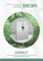
Каталог продукции Веза 2026 - Шкафы управления для систем приточно-вытяжной противодымной вентиляции ШКВАЛ. pdf, 6.57 Mb
Каталог шкафов управления ППУ ШКВАЛ для систем приточно-вытяжной противодымной вентиляции: назначение и типы, номенклатура, конструкция, габаритные размеры и масса, маркировка, схемы внешних соединений, комплект поставки. -

Каталог продукции Веза - Противопожарный вентилятор ОСА-ЭВО-ДУВ. pdf, 9.16 Mb
Каталог противопожарных осевых вентиляторов ОСА-ЭВО-ДУВ: назначение, конструкция и исполнения, аэродинамические и технические характеристики, габаритные размеры, обозначение при заказе.
Новое в инструкциях
-
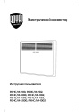
Электрические конвекторы Royal Thermo серии Capella RCHC/M. pdf, 5.01 Mb
Модели: RCHC/M-500, 502, 1000, 1002, 1500, 1502, 2000, 2002. Инструкция пользователя: устройство конвектора, управление прибором, уход и обслуживание, монтаж, хранение и транспортирование, технические характеристики, гарантийный талон. -
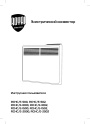
Электрические конвекторы Royal Thermo серии Capella RCHC/E. pdf, 5.01 Mb
Модели: RCHC/E-500, 502, 1000, 1002, 1500, 1502, 2000, 2002. Инструкция пользователя: устройство конвектора, управление прибором, уход и обслуживание, монтаж, хранение и транспортирование, технические характеристики, гарантийный талон. -

Бойлеры косвенного нагрева Royal Thermo. Правила установки. pdf, 251.55 Kb
Схема-памятка по установке бойлера косвенного нагрева: подключение к котлу и контурам ГВС/ХВС, группа безопасности, расширительный бак, диэлектрические муфты, фильтр очистки воды, заземление.