

Инструкции на Сплит - системы Midea серии Blanc
Настенные сплит-системы Midea серии MSMA1A-07HRN1, MSMA1A-09HRN1, MSMA1B-12HRN1, MSMA1C-18HRN1, MSMA1D-24HRN1, MOAB02-07HN1, MOAB02-09HN1, MOBA01-12HN1, MOBA03-18HN1, MOCA02-24HN1. Инструкция по техническому обслуживанию.
Смотрите также: Инструкция по монтажу →Инструкция по эксплуатации →
Загружаем документ…
Текст инструкции
-
Blanc ON-OFF Series
Service Manual 2016 MSMA1A-07HRN1 / MOAB02-07HN1 MSMA1A-09HRN1 / MOAB02-09HN1 MSMA1B-12HRN1 / MOBA01-12HN1 MSMA1C-18HRN1 / MOBA03-18HN1 MSMA1D-24HRN1 / MOCA02-24HN1 1
-
1. Precaution
1.1 Safety Precaution To prevent injury to the user or other people and property damage, the following instructions must be followed. Incorrect operation due to ignoring instruction will cause harm or damage. Before service the unit, be sure to read this service manual at first. 1.2 Warning …
-
There is risk of fire or electric shock
Do not touch (operation) the product with wet hands. Do not place a heater or other appliance near the power cable. There is risk of fire and electric shock. Do not allow water to run into electrical parts. It may cause fire, failure of the product, or electric shock. Do not store or use…
-
Do not install the product where it will be exposed to sea wind (salt spray) directly. It may cause corrosion on the product. Corrosion, particularly on the condenser and evaporator fins, could cause product malfunction or inefficient operation. Operational Do not expose the skin directly to…
-
2. Function
Model Names of Indoor/Outdoor Units On-Off 6 Capacity Indoor units Outdoor units 7k MSMA1A-07HRN1 MOAB02-07HN1 9k MSMA1A-09HRN1 MOAB02-09HN1 12k MSMA1B-12HRN1 MOBA01-12HN1 18k MSMA1C-18HRN1 MOBA03-18HN1 24k MSMA1D-24HRN1 MOCA02-24HN1 Service manual
-
3. Specification
Indoor model name MSMA1A-07HRN1 MSMA1A-09HRN1 MSMA1B-12HRN1 Outdoor model name MOAB02-07HN1 MOAB02-09HN1 MOBA01-12HN1 220-240V- 50Hz, 1Ph 220-240V- 50Hz, 1Ph 220-240V- 50Hz, 1Ph Btu/h 7000 9000 12000 kW 2,05 2,64 3,52 Input W 639 822 1096 Rated current A 2.8 3.6 4.8 W/W 3,21 3,21 3,21 Btu/h 8000…
-
Indoor model name
-
Model
-
4. Dimension
4.1 Indoor Unit Model W D H MSMA1A-07HRN1 MSMA1A-09HRN1 MSMA1B-12HRN1 MSMA1C-18HRN1 MSMA1D-24HRN1 1040 235 327 Service manual 11
-
For MSMA1A-07HRN1, MSMA1A-09HRN1,
12 Service manual
-
For MSMA1B-12HRN1,
For MSMA1C-18HRN1, Service manual 13
-
For MSMA1D-24HRN1,
14 Service manual
-
4.2 Outdoor Unit
-
For MOAB02-07HN1, MOAB02-09HN1,
16 Service manual
-
For MOBA01-12HN1, MOBA03-18HN1,
-
For MOCA02-24HN1,
18 Service manual
-
5. Capacity tables
-
MSMA1A-09HRN1 / MOAB02-09HN1
-
MSMA1B-12HRN1 / MOBA01-12HN1
-
MSMA1C-18HRN1 / MOBA03-18HN1
-
MSMA1D-24HRN1 / MOCA02-24HN1
-
6. Refrigerant Cycle Diagram
INDOOR OUTDOOR CHECK VALVE (Heating Model only) LIQUID SIDE 2-WAY VALVE CAPILIARY TUBE HEAT EXCHANGE (EVAPORATOR) HEAT EXCHANGE (CONDENSER) T1 Room temp. sensor T2 Evaporator temp. sensor GAS SIDE 4-WAY VALVE 3-WAY VALVE ACCUMULATOR COOLING COMPRESSOR 24 HEATING Service manual
-
7. Installation Details
7.1 Wrench torque sheet for installation Outside diameter Torque Additional tightening torque mm inch N.cm N.cm Ф6.35 1/4 1500(153kgf.cm) 1600(163kgf.cm) Ф9.52 3/8 2500(255kgf.cm) 2600(265kgf.cm) Ф12.7 1/2 3500(357kgf.cm) 3600(367kgf.cm) Ф15.9 5/8 4500(459kgf.cm) 4700(479kgf.cm) Ф19 3/4…
-
7.3 Pipe length and the elevation
-
7.4 Installation for the first time
Air and moisture in the refrigerant system have undesirable effects as below: Pressure in the system rises. Operating current rises. Cooling or heating efficiency drops. Moisture in the refrigerant circuit may freeze and block capillary tubing. Water may lead to corrosion of parts in the refrigerant…
-
2. Air purging by refrigerant
Procedure: 1). Confirm that both the 2-way and 3-way valves are set to the closed position. 2). Connect the charge set and a charging cylinder to the service port of the 3-way valve. 3). Air purging. Open the valves on the charging cylinder and the charge set. Purge the air by loosening the flare…
-
Open the valve at the bottom of the cylinder and press the check valve on the charge set to purge the air (be careful of the liquid refrigerant). 3) Put the charging cylinder onto the electronic scale and record the weight. 4) Operate the air conditioner at the cooling mode. 5) Open the valves (Low…
-
7.6 Re-installation while the indoor unit need to be repaired
1. Collecting the refrigerant into the outdoor unit Procedure 1). Confirm that both the 2-way and 3-way valves are set to the opened position Remove the valve stem caps and confirm that the valve stems are in the opened position. Be sure to use a hexagonal wrench to operate the valve stems. 2).…
-
the 2-way valve approximately 45’ for 3 seconds then closing it for 1 minute; repeat 3 times
After purging the air, use a torque wrench to tighten the flare nut on the 2-way valve. 4). Check the gas leakage Check the flare connections for gas leakage. 5). Discharge the refrigerant. Close the valve on the charging cylinder and discharge the refrigerant by loosening the flare nut on the 2-way…
-
1). Connect the charge hose to the charging cylinder, open the 2-way valve and the 3-way valve
Connect the charge hose which you disconnected from the vacuum pump to the valve at the bottom of the cylinder. If the refrigerant is R410A, make the cylinder bottom up to ensure liquid charge. 2). Purge the air from the charge hose Open the valve at the bottom of the cylinder and press the check…
-
8. Wiring Diagram
8.1 Indoor Unit MSMA1A-07HRN1, MSMA1A-09HRN1, MSMA1B-12HRN1, MSMA1C-18HRN1 Service manual 33
-
MSMA1D-24HRN1,
34 Service manual
-
8.2 Outdoor Unit
MOAB02-07HN1, MOAB02-09HN1, MOBA01-12HN1, MOBA03-18HN1, Service manual 35
-
MOCA02-24HN1
36 Service manual
-
9. Operation Characteristics
Mode Cooling operation Heating operation Drying operation Room temperature 17℃~32℃ 0℃~30℃ 10℃~32℃ Outdoor temperature 18℃~43℃ -7℃~24℃ 11℃~43℃ Temperature CAUTION: 1. If the air conditioner is used beyond the above conditions, certain safety protection features may come into operation and cause the…
-
10. Electronic function
10.1 Abbreviation T1: Indoor room temperature T2: Coil temperature of evaporator T3: Coil temperature of condenser T4: Outdoor ambient temperature T5: Compressor discharge temperature 10.2 Display function 10.2.1 Icon explanation on indoor display board. Digital display: Displays the temperature…
-
Dispalys ‘
Blanc On-off ’ under 8℃ heating operation. WIFI control display (optional) Displays when the WIFI control feature is activated. (Not available when the unit does not have this function) NOTE: A guide on using the infrared remote is not included in this literature package. Service manual 39
-
10.3 Main Protection
10.3.1 Time Delay at restart for compressor. Less than 1 minute delay for the 1st time start-up and 3 minutes delay for others. 10.3.2 Sensor protection at open circuit and breaking disconnection. 10.3.3 Zero crossing detection error protection If AC can not detect zero crossing signal for 4 minutes…
-
(3) Indoor fan can be set to high/med/low/auto
(4) The louver operates the same as in cooling mode. (5) Auto fan: High Medium Low 10.4.2 Cooling Mode 10.4.2.1 Compressor running rules When indoor room temp.T1 is lower than setting value, the compressor and outdoor fan will shut off. T1 On Off 10.4.2.2 Outdoor fan running rules The On-off outdoor…
-
T1-Ts
High Medium Low 10.4.2.4 Low evaporator coil temperature T2 protection T2 On Off When the evaporator coil temp.T2 keeps lower than setting value, the compressor and outdoor fan will shut off. 10.4.2.5 High condenser temperature T3 protection (only for MSMAD-24HRN1-QB8W) T3 Compressor Off Compressor…
-
10.4.3 Heating Mode
10.4.3.1 Compressor running rules: When indoor room temp.T1 is higher than setting value the compressor and outdoor fan will shut off. T1 Off On 10.4.3.2 Outdoor fan running rules: The outdoor units have single fan speed. The outdoor fan will run following the compressor except when AC is in…
-
Condition of ending defrosting
If any one of the following items is satisfied, the defrosting will terminate and the machine will turn to normal heating mode. (1) The defrosting time is reached to the setting value. (2) The defrosting has been running for 3 minutes and T2≥TCDE1℃. (3) The defrosting has been running for 2 minutes…
-
(3) After setting the mode, AC will run in auto mode if the compressor keeps not running for certain time. 10.4.5 Drying mode 8.4.5.1 The compressor is cycled running with 10 minutes on and then 5 minutes off. The indoor fan will keep running at low speed. 8.4.5.2 In drying mode, if room temperature…
-
10.4.11 Follow me (optional)
1) If the indoor PCB receives the signal which results from pressing the FOLLOW ME button on remote controller, the buzzer will emit a sound and this indicates the follow me function is initiated. But when the indoor PCB receives signal which sent from remote controller every 3 minutes, the buzzer…
-
will display the maximum value or minimum
value. Service manual 47
-
11. Troubleshooting
11.1 Indoor Unit Error Display Operation lamp Timer lamp Display ☆ 1 time X E0 EEPROM parameter error ☆ 2 times X E1 Indoor / outdoor units communication error(only for MSMAD-24HRN1-QB8W) ☆ 3 times X E2 Zero-crossing signal detection error ☆ 4 times X E3 Indoor fan speed has been out of control ☆ 5…
-
11.2 Trouble shooting
11.2.1 EEPROM parameter error diagnosis and solution (E0) Error Code E0 Malfunction decision Indoor or outdoor PCB main chip does not receive feedback conditions from EEPROM chip. Supposed causes ● Installation mistake ● PCB faulty Trouble shooting: EEPROM: a read-only memory whose contents can be…
-
11.2.2 Indoor / outdoor unit’s communication diagnosis and solution (E1)
Error Code E1 Malfunction decision Indoor unit does not receive the feedback from outdoor unit during conditions 120 seconds. Supposed causes ● Wiring mistake ● Indoor or outdoor PCB faulty Trouble shooting: 50 Service manual
-
11.2.3 Zero crossing detection error diagnosis and solution (E2)
Error Code E2 Malfunction decision When PCB does not receive zero crossing signal feedback for 4 conditions minutes or the zero crossing signal time interval is abnormal. Supposed causes ● Connection mistake ● PCB faulty Trouble shooting: Service manual 51
-
11.2.4 Fan speed has been out of control diagnosis and solution (E3)
Error Code E3 Malfunction decision When indoor fan speed keeps too low (300RPM) for certain time, conditions the unit will stop and the LED will display the failure. Supposed causes ● Wiring mistake ● Fan ass’y faulty ● Fan motor faulty ● PCB faulty Trouble shooting: 52 Service manual
-
Index1
1: Indoor AC Fan Motor Power on and set the unit running in fan mode at high fan speed. After running for 15 seconds, measure the voltage of pin1 and pin2. If the value of the voltage is less than 100V(208~240V power supply)or 50V(115V power supply), the PCB must has problems and need to be…
-
11.2.5 Open circuit or short circuit of temperature sensor diagnosis and solution (E4)
Error Code E4/E5/F2 Malfunction decision If the sampling voltage is lower than 0.06V or higher than 4.94V, conditions the LED will display the failure. Supposed causes ● Wiring mistake ● Sensor faulty ● PCB faulty Trouble shooting: 54 Service manual
-
11.2.6 Indoor PCB /Display board communication error (E7)
Error Code E7 Malfunction decision Indoor PCB does not receive feedback from Display board. conditions Supposed causes ● Wiring mistake ● PCB faulty ● Display board malfunction Trouble shooting: Service manual 55
-
11.2.7 Refrigerant Leakage Detection diagnosis and solution(EC)
Error Code EC Malfunction decision Define the evaporator coil temp.T2 of the compressor just starts conditions running as Tcool. In the beginning 5 minutes after the compressor starts up, if T2 <Tcool-2℃ does not keep continuous 4 seconds and this situation happens 3 times, the display area will…
-
Main parts check
1.Temperature sensor checking Disconnect the temperature sensor from PCB, measure the resistance value with a tester. Temperature Sensors. Room temp.(T1) sensor, Indoor coil temp.(T2) sensor, Outdoor coil temp.(T3) sensor, Outdoor ambient temp.(T4) sensor, Compressor discharge temp.(T5) sensor.…
-
Appendix 2 Temperature Sensor Resistance Value Table for T5 (°C --K)
Схемы, таблицы и рисунки — в просмотре документа выше. Клик по номеру страницы открывает её в просмотре.
Новое в каталогах
-
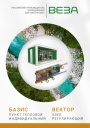
Каталог продукции Веза 2025 - Пункт тепловой индивидуальный БАЗИС, узел регулирующий ВЕКТОР. pdf, 8.85 Mb
Каталог индивидуальных тепловых пунктов БАЗИС, узлов регулирующих ВЕКТОР и блочных тепловых пунктов: назначение, схемы, комплектация, технические характеристики, габаритные размеры. -
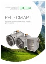
Каталог продукции Веза 2024 - Регуляторы переменного расхода воздуха РЕГ-СМАРТ для VAV-систем. pdf, 1.83 Mb
Каталог регуляторов переменного расхода воздуха РЕГ-СМАРТ для VAV-систем: назначение, конструкция, исполнения, технические характеристики, габаритные размеры, обозначение при заказе. -
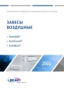
Каталог продукции Веза 2025 - Воздушные завесы. pdf, 4.97 Mb
Каталог воздушных завес Веза AeroWall, AeroGuard, AeroBlast: назначение, конструкция и исполнения, технические характеристики, габаритные размеры, подбор.
Новое в инструкциях
-

Полупромышленные канальные сплит-системы Shuft серии SFLC_D. pdf, 10.37 Mb
Модели: SFLC_D/in-18…60HN1_V2, SFLC_D/out-18…60HN1_V2. Руководство по эксплуатации: устройство, проводной пульт, монтаж, электрические схемы подключения, размеры, технические характеристики, устранение неисправностей, протоколы приёмки и тестового запуска, гарантийный талон. -

Полупромышленные напольно-потолочные сплит-системы Shuft серии SFLC_CF. pdf, 8.93 Mb
Модели: SFLC_CF/in-18…60HN1_V2, SFLC_CF/out-18…60HN1_V2. Руководство по эксплуатации: устройство, проводной пульт, монтаж, электрические схемы подключения, размеры, технические характеристики, устранение неисправностей, протоколы приёмки и тестового запуска, гарантийный талон. -

Мульти-сплит-системы Shuft серии FMI. pdf, 4.82 Mb
Модели: внутренние блоки SFMS/I-07…18 HB FMI/N8/IN/WHITE, наружные SFMO/I-14…42 FMI-2…5/N8/OUT. Руководство по эксплуатации: технические характеристики, управление кондиционером, монтаж, техническое обслуживание, поиск и устранение неисправностей, возможная комплектация блоков, гарантийный талон.