

Инструкция на Модели: MDVOS-150HVR1A, MDVOS-192HVR1A, MDVOS-250HVR1A. Сервисное руководство: общая информация, компоновка и холодильный контур, управление, настройки, электрические компоненты и схемы, диагностика и
Модели: MDVOS-150HVR1A, MDVOS-192HVR1A, MDVOS-250HVR1A. Сервисное руководство: общая информация, компоновка и холодильный контур, управление, настройки, электрические компоненты и схемы, диагностика и коды ошибок, поиск неисправностей. Документ на английском языке.
Смотрите также: Руководство по установке и эксплуатации →
Загружаем документ…
Текст инструкции
-
R410A
Service Manual Quantum Series №/ №/ = & MDVOS-150HVR1A MDVOS-192HVR1A MDVOS-250HVR1A
-
Мм
Quantum 50/60Hz Jenue|] ad1Asas saisag шпзиепто AGIN
-
Part 1
General Information 1 Indoor and Outdoor Unit Capacities 4 2 External Appearance 5 3 Nomenclature 6 Part 1 - General Information 3
-
1 Indoor and Outdoor Unit Capacities
Table 1-1.1 Outdoor Unit Model MDV Quantum Series Service Manual MDVOS-150HVR1A MDVOS-192HVR1A MDVOS-250HVR1A Indoor Unit Indoor Unit Capacity(kW) Model High Static Pressure Duct 45 MDVID3-150HVR1E Floor Standing 45 MDVIFS-150HVR1D Floor Standing 45 MDVIFST-150HVR1D High Static Pressure Duct 22.4…
-
2 External Appearance
2.1 Indoor Units Table 1-2.1: Indoor unit appearance Four-way Cassette Wall-mounted Medium Static Pressure Duct High Static Pressure Duct Ceiling & Floor Floor Standing Part 1 - General Information 2.2 Outdoor Units Table 1-2.2: Single outdoor unit appearance 16HP 20/24HP 5
-
3 Nomenclature
-
Part 2
Component Layout and Refrigerant Circuits 2 Piping Diagrams 10 3 Refrigerant Flow Diagrams 13 7 Part 2 - Component Layout and Refrigerant Circuits 1 Layout of Functional Components 8
-
1 Layout of Functional Components
1.1 8-16HP layout of functional components Figure 2-1.1: 16HP layout of functional component 7 6 MDV Quantum Series Service Manual Legend No. 8 Parts name No. Parts name 1 Compressor 11 Stop valve (liquid side) 2 Oil separator 12 Electronic expansion valve (EEVC) 3 High pressure switch 13 Electronic…
-
1.2 18-24HP layout of functional components
Figure 2-1.2: 20-24HP layout of functional components Part 2 - Component Layout and Refrigerant Circuits Legend No. Parts name No. Parts name 1 Compressor 11 Stop valve (liquid side) 2 Oil separator 12 Electronic expansion valve (EEVC) 3 High pressure switch 13 Electronic expansion valve…
-
2 Piping Diagrams
2.1 8-16HP piping diagram Figure 2-2.1: 16HP piping diagram 7 7 T3 T8 ST1 6 21 T4 E S C 9 TL SV5 SV7 14 T6B HPS PL MHE T6A 1 ACC INV1 19 13 Heat SV8A 15 Customized EEVE T7C1 T 71 MDV Quantum Series Service Manual O/S PH 3 Tg EEVA 8 12 EEVC 17 T5 11 Legend 10 No. Parts name No. Parts name 1…
-
2.2 18-24HP piping diagram
Figure 2-2.2: 20-24HP piping diagram 7 7 T3 T8 ST1 6 21 T4 E S C 9 TL SV5 SV7 14 T6B HPS PL MHE T6A ACC INV1 19 13 Heat SV8A 15 Customized EEVE 1 T 71 T7C1 8 Part 2 - Component Layout and Refrigerant Circuits O/S PH 3 Tg EEVA 12 EEVC 17 T5 11 Legend No. Parts name No. Parts name 1 Compressor 17…
-
2.3 Key components
1. Oil separator: Separates oil from gas refrigerant pumped out of the compressor and quickly returns it to the compressor. Separation efficiency is up to 99%. 2. Gas-liquid separator: Separates liquid refrigerant from gas refrigerant, stores liquid refrigerant and oil to protect compressor from…
-
Refrigerant Flow Diagrams 3.1 Cooling operation Figure 2-3.1: 16-24HP refrigerant flow during cooling operation Part 2 - Component Layout and Refrigerant Circuits Note: There is no SV8A for 20/24HP outdoor units. High temperature, high pressure gas High temperature, high pressure liquid Low…
-
3.3 Oil return operation in cooling mode
MDV Quantum Series Service Manual Figure 2-3.3: 16-24HP refrigerant flow during oil return operation in cooling mode Note: There is no SV8A for 20/24HP outdoor units. High temperature, high pressure gas High temperature, high pressure liquid Low temperature, low pressure gas 3.4 Oil return operation…
-
1 General Control Scheme Flowchart
Sections 2 to 8 on the following pages detail when each of the controls in the flowchart below is activated. 2 Stop operation ▪ Abnormal shutdown ▪ System stops ▪ A unit stops when the load demanded decreases 3 Standby control ▪ Crankcase heater control Special control 7 MDV Quantum Series Service…
-
2 Stop Operation
The stop operation occurs for one of the three following reasons: 1. Abnormal shutdown: in order to protect the compressors, if an abnormal state occurs,the system will makes a 'stop with thermos-off' operation and an error code will be displayed on the outdoor unit digital displays. 2. The system…
-
3 Standby Control
3.1 Crankcase Heater Control The crankcase heater is used to prevent refrigerant from mixing with compressor oil when the compressors are stopped. The crankcase heater is controlled mainly according to the minimum of discharge temperatures. When the minimum of discharge temperatures is above 45°C…
-
4.3 Startup Control for Cooling Operation
Table 3-4.1: Component control during startup in cooling mode Component Wiring diagram label Inverter INV1 compressor Inverter fan 1 ODU FANB Four way valve ST1 Electronic expansion valve IDU Ending conditions 0Hz 0Hz 0 Step If T4 exceeds the operating range, off 2min after the 12th gear is operated…
-
4.4 Startup Control for Heating Operation
Table 3-4.2: Component control during startup in heating mode Component Wiring diagram label STEP3 STEP4 STEP5 Adjust according to the high pressure and low pressure etc. 0Hz 0Hz 0Hz 0Hz Inverter fan 1 Inverter fan 2 0 Step 0 step 0 step 0 step Start: 0 step, then adjust by the high pressure and PI…
-
5 Normal Operation Control
5.1 Component Control during Normal Operation Table 3-5.1: Outdoor unit component control during normal operation Component Wiring diagram label Inverter compressor COMP(A) Inverter fan 1 FANA Inverter fan 2 FANB Cooling Heating PI control, High pressure protection, Low pressure protection…
-
5.2 Compressor Control
Cooling operation Compressor frequency is PI controlled to keep low pressure at target temperature. Te: Low pressure equivalent saturation temperature (°C) Tes: Target Te value. Tes will be decided by Te setting, if you choose Auto that means except Te setting, the Tes would be adjusted according to…
-
5.3 Heat Exchanger Control
Quantum 50/60Hz The mode of the outdoor units is uniformly controlled by the master outdoor unit: the master outdoor unit check status of the outdoor unit heat exchanger and sends the calculation result to each slave unit, and each slave unit control their own four-way valve, fan and EEVA. Part 3…
-
5.4 Electronic Expansion Valve Control
5.4.1 EEVA control The positions of electronic expansion valves EEVA are controlled in steps from 0/0 (fully closed) to 480/2880 (fully open). 5.4.1.1 Outdoor unit heat exchanger is performed via the evaporator MDV Quantum Series Service Manual when outdoor temperature ≥- 8°C: This function is used…
-
5.5 Outdoor Fan Control
The speed of the outdoor unit fans is adjusted in steps, as shown in Table 3-5.9 Table 3-5.9: Outdoor fan speed steps Fan speed index Fan speed (rpm) 20-24HP FANA FANB FANA FANB 1030 1090 1160 1030 1090 1160 1000 1050 1090 1020 1070 1110 cooling Stop operation, Startup or defrosting control[1] 18/20…
-
Table 3-5.10 Upper limit fan step in static pressure mode
cooling Static Pressure mode Outdoor unit/HP 0Pa 20Pa 40Pa 60Pa 80Pa Heating MDV Quantum Series Service Manual Static Pressure mode Outdoor unit/HP 0Pa 20Pa 40Pa 60Pa 80Pa Note: 1. Standard models can provide 35Pa maximum external static pressure. High static pressure models can provide 80Pa maximum…
-
6 Protection Control
6.1 High Pressure Protection Control This control protects the system from abnormally high pressure and protects the compressors from transient spikes in pressure. Figure 3-6.1: High pressure protection control Normal operation Pc ≥ 4.15MPa Pc < 3.5MPa High pressure protection, error code P12 is…
-
6.4 Over-current Protection Control
Over current protection control is performed to prevent tripping due to transient inverter over-current. It protects the compressors from abnormally high currents. It is performed for each compressor. Figure 3-6.6: Over-current protection control Normal operation Current ≥ CurrentA Current <…
-
6.6 Inverter Module Temperature Protection Control
This control protects the compressors from abnormally high currents and protects the inverter modules from abnormally high temperatures. It is performed for each compressor and inverter module. 6.6.1 Error code F62 Figure 3-6.9: Inverter module temperature protection control Normal operation Ntc…
-
6.8 High Pressure Ratio Protection Control
This high pressure ratio protection control is used to prevent the activation of protection devices due to abnormal increase of high pressure ratio, and to protect compressors against the transient increase of high pressure ratio. It is performed for entire system. Figure 3-6.11: High pressure ratio…
-
7 Special Control
7.1 Oil Return Operation In order to prevent compressors from running out of oil, the oil return operation is conducted to recover oil that has flowed out of the compressor(s) and into the piping system. This operation is performed for all units including units that are in standby. When the outdoor…
-
Cooling indoor unit
FAN Electronic expansion valve (EEV) 500P EEV Thermo ON unit Thermo OFF unit Stop or Fan Thermo ON unit Thermo OFF unit Stop or Fan Keep the previous fan speed Superheat control 80pls 80pls MDV Quantum Series Service Manual 7.1.2 Heating Oil Return Control It’s basically identical with defrosting…
-
7.2 Defrosting Operation
In order to recover heating capacity, the defrosting operation is conducted when the outdoor unit heat exchanger is performing as an evaporator. The defrosting operation is controlled according to outdoor ambient temperature, outdoor heat exchanger temperature, indoor heat exchanger temperature and…
-
8 Other Control
8.1 Overload control Overload control is used to maintain comfort requirement (i.e. outlet air temperature) and keep proper system pressure. Figure 3-8.1: Overload control Normal operation Indoor unit operation ratio <105% Indoor unit operation ratio ≥ 130% Overload control, indoor units operates in…
-
8.4 Low Noise Mode
Low noise mode is used to decrease the noise produced by outdoor units. There are 14 kinds of low noise mode: Silent mode1~ Silent mode14. When low noise mode activating, both the fan step and compressor are limited. Table 3-8.4: Low noise mode ODU 16HP 20HP 24HP Silent mode 1 Silent mode 2 Silent…
-
Part 4
Field Settings 36 1. Overview 37 2. Digital display and button settings 37 3. System Parameter Check 47
-
1. Overview
This chapter describes how the system configuration can be implemented once the installation is completed, and other relevant information. It contains the following information: Implement field settings Using the Check function 2. Digital display and button settings Part 4 - Field Settings 2.1…
-
2.3 Menu mode
Only master unit has the full menu functions, slave units only have error codes check and cleaning functions. 1. Long press SW5 "MENU" button for 5 seconds to enter menu mode, and the digital display displays "n0". 2. Press SW3 / SW4 "UP / DOWN" button to select the first level menu "n0" to "n9"or…
-
Menu mode function
Table 4-2.3 Menu mode function: First level menu n0 (Information query) Second level menu Specified menu mode 0 (History error) 0 Query History error (last ten error codes) 1 Cleaning history error 1 (address) 0 Query Indoor unit's address 2 Query the address of Indoor unit in power-off condition 2…
-
First level menu
Second level menu 1 (Silent mode) 2 (static pressure) Specified menu mode Description 8 Silent mode 8 9 Silent mode 9 A Silent mode 10 b Silent mode 11 C Silent mode 12 d Silent mode 13 E Silent mode 14 0 0Pa static pressure 1 20Pa static pressure 2 40Pa static pressure(Customized) 3 60Pa static…
-
n3
(Installation parameters) 7 (Ambient temperature) 0 Enable Internal ambient temperature sensor(T4) √ 1 Enable External ambient temperature sensor(T10-Optional) - 0 Reserved - 1 Reserved √ 0 Reserved - 1 Reserved √ 0 - Set address of Outdoor unit - 1 - Set Network address of Outdoor unit 0 2 - Set…
-
First level menu
n6 (evaporation and condensation temperature) n8 Second level menu 0 (target condensation temperature of the indoor unit) 7 (Low noise defrosting) 1 MDV Quantum Series Service Manual n9 nc[1] (Dry contact function) 1 2 Notes: 1. 42 Using with setting [n2-8-0] or [n2-8-1]. Specified menu mode…
-
2.4 Special mode introduction
2.4.1 Priority mode setting Priority mode can only be set on the master unit. When an indoor unit is in mode conflict with the outdoor units the unit displays the mode conflict error. The digital display on indoor main PCB will display error code E0. There are ten priority mode options: 1. Auto…
-
5. Changeover mode: Before using this mode, you need to set the VIP indoor unit address. The default VIP address is 63, the VIP address also can be changed through menu mode“n1-6”. In changeover mode, if the VIP indoor unit is operating, the outdoor units will operate in the mode of the VIP indoor…
-
Step1:preparation
Step1:preparation Step2:Calculate static Step2:Calculate static pressure of of Outdoor unit pressure Outdoor unit Step3:Indoor and outdoor temperatures are within the allowable range of test run No Display error code U32/U33/U34 Yes Turn on Turn on all all indoor indoor units units Step4:The stop…
-
3. System refrigerant quantity detection
After entering this mode, the system will automatically run and finally output the diagnostic results of the system refrigerant quantity. Diagnostic results: a) b) c) d) e) Normal: Digital display “d34” f) No result- The system operation conditions do not meet the functional requirements: Digital…
-
3. System Parameter Check
3.1 UP / DOWN system check button Before pressing UP or DOWN button, allow the system to operate steadily for more than an hour. On pressing UP or DOWN button, the parameters listed in below table will be displayed in sequence. Table 4-3.1 system check list: DSP1 content Parameters displayed on DSP2…
-
DSP1 content
Parameters displayed on DSP2 Remarks 28.-- Primary current(A) Actual value = value displayed /10 29.-- Inverter compressor A current (A) Actual value = value displayed /10 30.-- Reserved - 31.-- EXVA position Actual value = value displayed × 24 32.-- Reserved - 33.-- EEVC position Actual value =…
-
DSP1 content
Parameters displayed on DSP2 Remarks 0 :No result 1 :Significantly insufficient 51.-- Refrigerant volume judgment (1) 2 :insufficient 3 :Normal 4 :excessive 5 :Significantly excessive 52.-- Dirty blockage rate (outdoor heat exchanger) 53.-- Fan historical error 54.-- Software version 55.-- Last…
-
1. Outdoor Unit Electric Control Box Layout
Figure 5-1.1: 16-24HP top layer of electric control box Main control board Part 5 - Electrical Components and Wiring Diagrams Communication terminals block Power supply terminals Figure 5-1.2: 16-24HP bottom layer of electric control box Filter board Inductor Reactor Compressor drive board DC fan…
-
Outdoor Unit Main Control Board 2.1 Outdoor unit main Control Board ports MDV Quantum Series Service Manual Figure 5-2.1: Outdoor unit main Control Board ports1 Notes: Label descriptions are given in Table 5-2.1: Main Control Board port . 52
-
Table 5-2.1: Main Control Board port
Label in Figure 5-2.1 Port code Content Port voltage 1 CN82 Reserved 5Vdc 2 CN36 Reserved 3.3Vdc 3 CN70 EEVA drive port 12Vdc 4 CN71 EEVB drive port(Reserved) 12Vdc 5 CN72 EEVC drive port 12Vdc 6 CN73 EXVE drive port 12Vdc Microchannel heat exchanger inlet temperature sensor(T6A) /Liquid pipe inlet…
-
2.2 Outdoor unit main Control Board components
2.2.1 Layout MDV Quantum Series Service Manual Figure 5-2.2: Outdoor unit main Control Board components 2.2.2 Function of buttons SW3 to SW6 Table 5-2.2: Function of buttons SW3 to SW6 Button SW3 (UP) SW4 (DOWN) SW5 (MENU) SW6 (OK) 54 Function In menu mode: previous and next buttons for menu modes.…
-
Quantum 50/60Hz Digital display output Table 5-2.4: Digital display output in different operating states Outdoor unit state Parameters displayed on DSP1 Parameters displayed on DSP2 The number of indoor units in Standby The address of outdoor unit communication with the outdoor DSP1 units Normal…
-
Compressor & Fan drive board 3.1 Corresponding table of Compressor & Fan drive board and outdoor units Table 5-2.5: Corresponding table of Compressor & Fan drive board and outdoor units Compressor & Fan drive board model Model 50A 16HP 75A 20-24HP 3.2 Compressor & Fan drive board of 50A MDV Quantum…
-
3.3 Compressor & Fan drive board of 75A
Quantum 50/60Hz Figure 5-2.5: Compressor & Fan drive board of 75A Part 5 - Electrical Components and Wiring Diagrams 57
-
3.4 Compressor & Fan drive board ports
MDV Quantum Series Service Manual Figure 5-2.6: Compressor & Fan drive board ports of 50A Table 5-2.6: Compressor & Fan drive board port Label in Port Feature Figure 5-2.5 code identifier 1 CN1 P-in 2 CN5 P-out 3 CN16 L1 Three phase power input of L1 phase 4 CN7 L2 Three phase power input of L2…
-
Table 5-2.6: Compressor & Fan drive board port
Label in Port Feature Figure 5-2.5 code identifier 6 CN38 - 7 CN26 - 8 CN3 DCFAN CN8/C 9 N9 O-Motor Content Port voltage Power supply terminal for DC fan drive board (P,N) 438Vdc~650Vdc(Rated 540Vdc; (Reserved) P is positive, N is negative) Fan module controls power supply(Reserved) 19V Three phase…
-
3.5 The installation guide of Compressor & Fan drive board
MDV Quantum Series Service Manual Figure 5-2.7: The installation guide of Compressor & Fan drive board 60
-
1. Before maintaining or repairing the outdoor unit, cut off the power supply of the outdoor unit for 5 minutes and use a mustimeter to ensure that the voltage is zero to avoid electric shock. Notice The unit has the low-power standby function. After entering this mode, only the power indicator of…
-
4. Wiring Diagrams
MDV Quantum Series Service Manual Figure 5-3.1: Outdoor unit wiring diagram 62
-
1 Error Code Table
1.1 Outdoor Error code table Table 6-1.1 Outdoor Error code table Error code Manual re-start Remarks required2 A01 Emergency shutdown Outdoor unit’s fault NO AAx No.x Inverter driver board does not match the main control board Outdoor unit’s fault NO xA61 No.x slave unit error Salve unit’s fault NO…
-
Table 6-1.1 Outdoor Error code table (continued)
Error code Error description Remarks Manual re-start required2 High pressure sensor error Sensor error NO P12 High pressure protection Pressure protection NO P13 High pressure switch protection Pressure protection NO P14 P12 protection occurs 3 times in 60 minutes Pressure protection YES P21 Low…
-
1.2 Installation and debugging error code table
Table 6-1.2 Installation and debugging error code table Error code Manual re- Remarks start required2 U11 Outdoor unit model is not set System configuration YES U12 Outdoor unit Capacity setting error System configuration YES U21 System contains the old Indoor Unit with old platforms System…
-
Table 6-1.3 Compressor drive error code table (continued)
Error code Error description Remarks Manual re-start required2 xL51 Out-of-step error Control error NO xL52 Locked-rotor protection Motor error NO xL6E Compressor motor lack of phase protection Diagnosis error NO xLBE High pressure switch operation Pressure protection NO xLB7 Other check exceptions…
-
Table 6-1.5 Status prompt code table (continued)
Status code Remarks d36 Refrigerant quantity judgment:Significantly insufficient Status hint NO d37 IDU connected to system is not common Status hint NO d38 Too low proportion of running IDUs Status hint NO d39 Failed to detect refrigerant amount during backup Status hint NO d42 Communication error…
-
2 Error in Main Control
2.1 A01: Emergency shutdown of Outdoor Units Digital display output Description ▪ Compressor protection shut down ▪ All Outdoor Units stop running ▪ Error codes are displayed only on master uint. Figure A The dry contact is open (taking Input1 as an example) Figure B The dry contact is closed…
-
A01
One or both of the following are true: nC0 = 3 or nC1 = 3 If nC0 3, ignore port Input1 in the following troubleshooting If nC1 3, ignore port Input2 in the following troubleshooting Yes Menu set item n28 = 0 Yes Are Input1 and Input2 of port CN28 of the main board connected to the external? (See…
-
Quantum 50/60Hz Digital display output Description ▪ xA61 shows a slave unit error with the ODU address of x (x = 1,2). ▪ All Outdoor Units stop running ▪ Error code are displayed only on master unit. ▪ ▪ ▪ Part 6 - Diagnosis and Troubleshooting ▪ Trigger / recover condition Trigger condition: Slave…
-
2.3 AAx: Inverter driver board X does not match the main control board
Digital display output Description ▪ No.x Inverter driver board does not match the main control board ▪ All units stop running. ▪ Error code is displayed on the unit with the error MDV Quantum Series Service Manual Trigger / recover condition ▪ Trigger condition: Parameters of the built-in drive in…
-
Digital display output ▪ ▪ ▪ ▪ ▪ ▪ Part 6 - Diagnosis and Troubleshooting ▪ ▪ ▪ ▪ Description No.x Recirculation Fan[1] is in error Unit with the error stop running. Error code is displayed on the unit with the error Trigger / recover condition Trigger condition: the difference between the actual…
-
Digital display output ▪ ▪ MDV Quantum Series Service Manual ▪ ▪ ▪ ▪ ▪ ▪ Description All units stop running Error code is displayed on the outdoor unit with the error. Trigger / recover condition Trigger condition: The main control board has not detected signals from the EEV for 2 minutes. Recover…
-
Digital display output ▪ ▪ ▪ ▪ ▪ Part 6 - Diagnosis and Troubleshooting ▪ ▪ ▪ Description All units stop running Error code is displayed on the outdoor unit with the error. Trigger / recover condition Trigger condition: The main control board has not detected signals from the EEV for 2 minutes.…
-
2.7 C13: The address of Outdoor Unit is repeated
Digital display output Description ▪ The address of Outdoor Unit is repeated. ▪ Error code is displayed on the master outdoor unit. MDV Quantum Series Service Manual Trigger /recover condition ▪ Trigger:Two or more outdoor units in the combined system have the same address ▪ Recover condition: The…
-
2.8 C21: Communication error between IDU and ODU
Digital display output Table 6.2.1 Communication troubleshooting list: ODU interface IDU interface PQE PQE PQE PQE IDU type V8 V6 Communication protocol n45-0, V8 protocol P Q communication n45-1, V6 protocol PQE communication n45-0, V8 protocol P Q communication n45-1, V6 protocol PQE communication…
-
C21
Is the communication protocol correct? No Select the correct communication protocol for the specific ODU interface, IDU interface, and IDU type according to Table 6.2.1. In the table, "/" in the [Digital display output] indicates normal communication state; otherwise, correction is required…
-
2.9 C26 Abnormal reduction in the number of indoor units
Quantum 50/60Hz Digital display output Description ▪ The number of online indoor units is smaller than the configured number ▪ All units stop running. ▪ Error code is only displayed on the master unit ▪ ▪ ▪ ▪ ▪ ▪ ▪ ▪ Possible causes The IDU address code is not set or is duplicated. The IDU is not…
-
C26
C26 Is the Is the IDU IDU address address code code not not set set or or duplicated. duplicated. Yes Yes Select one Select one of of the the following following solutions solutions Solution Reset the the address. address. In In menu menu n44, n44, set [0] Solution 1: 1: Reset set to to [0]…
-
2.10 C28: Abnormal increase in the number of indoor units
Quantum 50/60Hz Digital display output ▪ ▪ ▪ ▪ ▪ ▪ ▪ ▪ C28 C28 Spot check Spot check item item 3: 3: Setting Setting the the number number of of IDUs IDUs Set the Set the number number of of IDUs. IDUs. Does match the the number of Does it it match number of installed IDUs in the the system? system?…
-
2.11 xC31: Communication error between No.x slave outdoor unit and master outduoor unit
Digital display output MDV Quantum Series Service Manual Description ▪ The No.x outdoor slave unit cannot communicate with the outdoor master unit. ▪ Outdoor units that display the error code stop running. ▪ Error code is only displayed on the slave unit with the error. Trigger / recover condition ▪…
-
2.12 C32: Abnormal reduction in the number of outdoor units
Quantum 50/60Hz Digital display output ▪ ▪ ▪ ▪ ▪ ▪ ▪ C32 C32 Spot Spot check check item item 0: 0: Address Address code code of of the the slave slave ODU ODU Yes Yes Ent er Ent er menu menu n40 n40 to to set set ODU ODU addresses again, again, 1-3 1-3 for addresses for slav slav ee O O DUs DUs…
-
2.13 C33: Abnormal increase in the number of outdoor units
Digital display output ▪ ▪ ▪ MDV Quantum Series Service Manual ▪ ▪ ▪ ▪ ▪ ▪ ▪ Description The number of online outdoor slave units detected by the outdoor master unit increases All units stop running. Error code is only displayed on the master unit Trigger / recover condition Trigger condition:One or…
-
2.14 xC41: Communication Error between main control board and No.x inverter driver board
Digital display output ▪ ▪ ▪ ▪ ▪ ▪ ▪ ▪ board are duplicate (the correct addresses are: "00" ▪ ▪ ▪ ▪ for No. 1 drive board and "01" for No. 2 drive board). The main power has L1/L2/L3 misphase or abnormal voltage. The filter board is damaged. No. x inverter drive board is damaged. The ODU main…
-
C41
Yes Measure the ODU main power L1/L2/L3. Is there phase loss or voltage failure? Eliminate the problems with the power supply accordingly No Measure the input voltage L1/L2/L3 after module rectification. Is there phase loss or voltage failure? Is there circuit break, misphase, or poor contact with…
-
Digital display output Error code E41 F81 Error description Outdoor ambient temperature sensor (T4) error(open/short) Gas pipe temperature sensor (Tg) error (open/short) Remarks Digital display output sensor error sensor error Outdoor heat exchanger liquid FC1 temperature sensor (TL) error sensor…
-
Description
▪ Temperature sensor error ▪ All units stop running. ▪ Error code is displayed on the unit with the error Trigger / recover condition ▪ Trigger condition:The main control board cannot obtain the normal AD value of the temperature sensor ▪ Recover condition:The main control board obtain the normal AD…
-
2. F41/FA1
F41/FA1 Correctly connect T3/T8 sensor Yes The sensor connection on main board is loose[1] No The sensor is sho rt-circu ited or fails[2] No PCB is damaged[3] Yes Replace the sensor No Replace the main board Automatic res toration in 5s? Troubleshooting Notes: [1].The port CN8 (T3/T8) on the main…
-
4. xF71
1F71, 2F71 T7C sensors are not connected to the compressor top or T7C1 and T7C2 are connected reversely to the compressor Yes Connect T7C sensors correctly to the compressor top and fix them with spring clips. No Yes Correctly connect T7C sensor T7C sensor is not connected or is in poor contact[1]…
-
Quantum 50/60Hz Digital display output ▪ ▪ ▪ ▪ ▪ ▪ ▪ ▪ ▪ ▪ 91 Part 6 - Diagnosis and Troubleshooting ▪ Description The temperature of the Tf/Ntc radiator is too high. All units stop running Error code is displayed on the outdoor unit with the Error Trigger/ Recover condition Trigger condition: F62…
-
F62, F6A
Yes Is the ODU check valve closed? Open the ODU check valve and power on. Does the error display again? No No Yes No Is the piping and wiring connected correctly? Correctly connect the piping and wiring, then power on. Does the error display again? No Yes Yes Yes Are the module board screws loose?…
-
2.17 F63: Non-inductive resistance Tr overtemperature protection
Digital display output ▪ ▪ ▪ ▪ ▪ ▪ Part 6 - Diagnosis and Troubleshooting ▪ ▪ ▪ Description The temperature of the Tr non-inductive resistance NTC is too high. All units stop running Error code is displayed on the outdoor unit with the Error Trigger/ Recover condition Trigger condition: The…
-
Digital display output ▪ ▪ ▪ ▪ MDV Quantum Series Service Manual ▪ ▪ ▪ ▪ ▪ ▪ ▪ 94 Description Discharge Temperature is over the limit. All outdoor Unit stop running Error code is displayed on the unit with the error Trigger / Recover condition Trigger condition: F72: Discharge Temperature…
-
Procdure
F72/F7A Yes Open the ODU check valve and power on. Does the error display again? Is the ODU check valve closed? No No Yes Is the piping and wiring connected correctly? Correctly connect the piping and wiring, then power on. Does the error display again? No Yes Yes Is the temperature of the discharge…
-
2.19 F75: Compressor discharge insufficient superheat protection
Digital display output MDV Quantum Series Service Manual ▪ ▪ ▪ ▪ Description Superheat degree of compressor discharge temperature is too low, triggering protection shutdown Determination during operation of outdoor unit. All units stop running. The error code is displayed on the outdoor unit with…
-
F75
Correctly connect the piping and wiring, then power on. Does the error display again? No Is the piping and wiring connected correctly? Yes Yes Figure I Do any of the following conditions occur? 1. T7C sensors are not connected to the compressor top 2. T7C1 and T7C2 are connected reversely to the…
-
2.20 P11: High pressure sensor error
Digital display output ▪ ▪ ▪ MDV Quantum Series Service Manual ▪ ▪ ▪ ▪ ▪ Description Open/short circuit error of high pressure sensor All units stop running. The error code is displayed on the Outdoor Unit with error. Trigger / recover condition Trigger condition: The high pressure sensor is…
-
2.21 P12/P14: High pressure protection
Quantum 50/60Hz Digital display output ▪ ▪ ▪ ▪ ▪ ▪ ▪ ▪ ▪ ��P12: Phigh pressure≥ 4.15 MPa. ��P14: P12 occurs 3 times within 100 minutes Recover condition: ��P12: Phigh pressure < 3.5MPa ��P14: Remove high pressure protection from Outdoor Unit Reset method: ��P12: Resume automatically. ��P14: Resume…
-
P12
Enter the MENU vacuum mode (n15) after power off. Wait for 1min. Are the HP and LP pressures close, and troubleshooting? No Yes If the HP pressure is too high, preferably check the following items. 1. Is the ODU check valve fully opened? 2. Is the piping and wiring connected correctly? 3. Are coils…
-
2.22 P13: High pressure switch protection
Quantum 50/60Hz Digital display output ▪ ▪ ▪ ▪ ▪ Part 6 - Diagnosis and Troubleshooting ▪ ▪ ▪ ▪ Description All units stop running Error code is displayed on the unit with the Error Trigger / recover condition Trigger condition: discharge pressure≥ 4.1MPa or the switch is open-circuited. Recover…
-
2.23 P21: Low pressure sensor error
Digital display output MDV Quantum Series Service Manual Description ▪ Open/short circuit Error in suction pressure sensor ▪ All units stop running. ▪ Error code is only displayed on the unit with the error. Trigger / recover condition ▪ Trigger condition: PLow Pressure<0.02MPa or PLow…
-
2.24 P22/P25: Low pressure protection
Quantum 50/60Hz Digital display output ▪ ▪ ▪ ▪ Description P22: Low pressure protection; P25: Low pressure protection occurs 3 times in 60 min. All units stop running. Error code is displayed on the unit with the error. ▪ ▪ ▪ ▪ ▪ Possible causes ODU check valve is not opened. Piping and wiring are…
-
P22/P25
Enter the MENU vacuum mode (n15) after power off. Wait for 1min. Are the HP and LP pressures close, and troubleshooting? No Yes If the LP pressure is too low, preferably check the following items. 1. Is the ODU check valve fully opened? 2. Is the piping and wiring connected correctly? 3. Are coils…
-
2.25 P24: Low Pressure too High Protection
Quantum 50/60Hz Digital display output ▪ ▪ ▪ ▪ ▪ ▪ ▪ Part 6 - Diagnosis and Troubleshooting ▪ ▪ Description All units stop running. ODU fault is determined based on the sensor. Error code is displayed on the unit with the error Trigger/ Recover condition Trigger condition: Suction pressure >1.6MPa…
-
P24
Is the pressure of the detection valve during s teady operation 1.6 MPa? [1] No No The main board is damaged. Rep lace it Is the main board pressure normal? [3] Yes Yes MDV Quantum Series Service Manual There may be 3 co nditio ns for the sys tem: 1. The ODU operates out of the operating temperature…
-
2.26 P31: Primary Side Overcurrent Protection
Quantum 50/60Hz Digital display output ▪ ▪ ▪ ▪ ▪ ▪ P31 No Is the ODU check valve opened? Open the check valve Yes Is there more refrigerant in the ODU (determined based on discharge/return air pressure and temperature)? Yes Discharge some of the refrigerant No Replace the drive board 107 Part 6…
-
Digital display output MDV Quantum Series Service Manual Description ▪ The DC bus current of No.x compressor is too high, triggering protection shutdown ▪ All units stop running. ▪ Error code is displayed on the unit with the error. Trigger / recover condition ▪ Trigger condition: P32: During…
-
XP32,XP33
Yes Open ODU stop valve ODU stop valve is closed? No Yes compressor cable is damaged Replacing the compressor Cable No Yes The resistance of the compressor wiring terminals to the ground is less than 1 MΩ The compressor is damaged. Replace the compressor No Part 6 - Diagnosis and Troubleshooting…
-
2.28 P51: High AC voltage protection
Digital display output Description ▪ The AC voltage of the system is too high, triggering the protection shutdown ▪ All units stop running ▪ Error code is displayed on the unit with the error. MDV Quantum Series Service Manual Trigger / recover condition ▪ Trigger condition:The AC voltage of Outdoor…
-
2.29 P52: Low voltage protection
Quantum 50/60Hz Digital display output ▪ ▪ ▪ ▪ ▪ ▪ Part 6 - Diagnosis and Troubleshooting ▪ ▪ ▪ ▪ Description The AC voltage of the system is too low, triggering the protection shutdown All units stop running. Error code is displayed on the unit with the error Trigger / recover condition Trigger…
-
2.30 P53: Phase B and N of the power cable are connected to the opposite protection
Digital display output Description ▪ System phase and neutral wires are connected reversely and fail the inspection ▪ All units stop running ▪ Error code is displayed on the unit with the error MDV Quantum Series Service Manual Trigger / recover condition ▪ Trigger condition: The drive board uploads…
-
2.31 P54: DC bus low voltage protection
Quantum 50/60Hz Digital display output Part 6 - Diagnosis and Troubleshooting Description ▪ The DC bus voltage of the compressor is too low ▪ All units stop running. ▪ Error code is displayed on the unit with the error Trigger / recover condition ▪ Trigger condition: The drive board uploads XL3E…
-
2.32 P55: DC bus ripple over protection
Digital display output ▪ ▪ ▪ ▪ MDV Quantum Series Service Manual ▪ ▪ ▪ ▪ ▪ Description The ripple of the DC bus on the module is over the limits. All units stop running. Error code is displayed on the unit with the error Trigger / recover condition Trigger condition: The DC bus ripple voltage…
-
Quantum 50/60Hz Digital display output Part 6 - Diagnosis and Troubleshooting Description ▪ No.x inverter driver board DC bus voltage is too low ▪ All units stop running. ▪ Error code is displayed on the unit with the error Trigger / recover condition ▪ Trigger condition: The inverter driver board…
-
MDV Quantum Series Service Manual Digital display output Description ▪ No.x inverter driver board DC bus voltage is too high ▪ All units stop running. ▪ Error code is displayed on the unit with the error Trigger / recover condition ▪ Trigger condition: The inverter driver board upload L31/J31 fails…
-
2.35 xP58: No.x inverter driver board DC bus voltage is seriously too high
Quantum 50/60Hz Digital display output Part 6 - Diagnosis and Troubleshooting Description ▪ No.x inverter driver board DC bus voltage is seriously too high ▪ All units stop running ▪ Error code is displayed on the unit with the error Trigger / recover condition ▪ Trigger condition: The inverter…
-
MDV Quantum Series Service Manual Digital display output Description ▪ The phase and neutral wires are connected reversely and fail the inspection. ▪ All units stop running ▪ Error code is displayed on the unit with the error Trigger / recover condition ▪ Trigger condition: phase and neutral wires…
-
Digital display output Description ▪ The EEPROM parameter of the ODU main control board is incorrect ▪ All units stop running. ▪ Error code is displayed on the unit with the error Trigger / recover condition ▪ Trigger condition:EEPROM parameter verification is incorrect ▪ Recover condition:EEPROM…
-
2.38 Pd1, Pd2: Anti-condensation protection
Digital display output ▪ ▪ ▪ MDV Quantum Series Service Manual ▪ ▪ ▪ ▪ ▪ ▪ ▪ ▪ ▪ ▪ 120 Description Anti-condensation protection All units stop running. Error code is displayed on the unit with the error Trigger / recover condition Trigger condition: Pd1: Liquid pipe inlet temperature (T5) remains…
-
Pd1/Pd2
Check the following aspects first: 1. EEVC terminal is correctly connected to the main board and the EEVC is correctly connected to the coil [1] 2. The temperature of T6A/T6B/T5 is consistent when spot check in ODU power-off condition. Is all of the above correct? No Connect the EEVC or sensor…
-
2.39 U11: Outdoor unit model is not set
Digital display output Description ▪ The outdoor unit model is not set into the main board. ▪ All units stop running ▪ Error code is displayed on the unit with the error MDV Quantum Series Service Manual Trigger / recover condition ▪ Trigger condition: The model information is not set. ▪ Recover…
-
2.40 U12: Outdoor unit Capacity setting error
Quantum 50/60Hz Digital display output Description ▪ The capability information of outdoor unit is not set ▪ All units stop running ▪ Error code is displayed on the unit with the Error Trigger / recover condition ▪ Trigger condition: The capability information of outdoor unit is not set ▪ Recover…
-
2.41 U21: The indoor unit connection is incorrect
Digital display output ▪ ▪ ▪ ▪ MDV Quantum Series Service Manual ▪ ▪ ▪ ▪ Description Connected to the 1st generation indoor unit or indoor unit address repeated in system All Outdoor units stop running Error code is displayed on the master unit Trigger / recover condition Trigger condition: • 1st…
-
2.42 U31: The test run was never successful
Quantum 50/60Hz Digital display output Description ▪ The system is not in the test run or the test run is unsuccessful ▪ All units stop running ▪ Error code is only displayed on the master unit. Part 6 - Diagnosis and Troubleshooting Trigger / Recover condition ▪ Trigger condition: • The system is…
-
2.43 U32, U33, U34: The temperature is not suitable for test run
Digital display output ▪ ▪ ▪ ▪ Description During the test run, the indoor or outdoor temperature exceeds the operating range All units stop running Error code is only displayed on outdoor unit Trigger /Recover condition Trigger condition: After entering into test run, the master unit estimates…
-
Digital display output ▪ ▪ ▪ ▪ Description The outdoor unit stop valve is not opened during the test run. All units stop running Error code is only displayed on the master unit. Trigger/ Recover condition Trigger condition: Error code U35 U37 The liquid side stop valve of the Discharge pressure of…
-
2. U37
U37 Are all ODU check valves opened? Yes Are piping and wiring signals of the system consistent? Yes Yes Is the Indoor unit faulty? No No Open all stop valves No Unify the piping and wiring signals Clear indoor unit faults according to the indoor unit error guidelines. MDV Quantum Series Service…
-
2.45 U38: Outdoor Unit has no address
Quantum 50/60Hz Digital display output ▪ ▪ ▪ ▪ ▪ ▪ ▪ U38 U38 Set the the address address of of each Set each ODU ODU in in menu menu "n40", "n40", 0 0 for the master master unit unit and and 1/2/3 for slave for the 1/2/3 for slave unit unit respectively. ODU addresses addresses of same respectively.…
-
2.46 U3A: The communication wiring is connected incorrectly
Digital display output Description ▪ Indoor unit piping and communication wiring are not connected in the same system. ▪ All units stop running ▪ Error code only displayed on the master unit. MDV Quantum Series Service Manual Trigger / Recover condition ▪ Trigger condition: Indoor unit piping and…
-
Quantum 50/60Hz Digital display output ▪ ▪ ▪ ▪ ▪ ▪ ▪ U3b U3b The ODU The ODU temperature temperature detected detected by T4 during the higher by T4 during the test test run run is is higher than than 10°C 10°C Check whether Check whether the the air of the the ODU ODU air inlet inlet and and outlet…
-
2.48 U3C: Changeover mode error
Digital display output ▪ ▪ ▪ MDV Quantum Series Service Manual ▪ ▪ ▪ ▪ ▪ Description ODU in changeover mode doesn’t set the VIP IDU address. ODUs stop running Error code only displayed on the master unit. Trigger / Recover condition Trigger condition: Outdoor unit in changeover mode, but the VIP…
-
Digital display output ▪ ▪ ▪ ▪ Description Combination ratio of indoor unit and outdoor unit is out of range All units stop running Error code only displayed on the master unit Trigger / Recover condition Trigger condition: 1) 2) Part 6 - Diagnosis and Troubleshooting Error code Description U41 The…
-
▪ Reset method: Resume manually
Possible causes ▪ Indoor units and outdoor units combination ratio is out of range. ▪ Outdoor unit address is repeated or the slave outdoor unit does not have an address. ▪ Individual series indoor unit is installed in combination with a combinable series. Procedure 1. U41 MDV Quantum Series Service…
-
3. U43
U43 Yes Are all IDU s of the sys tem AHU KIT (air discharge co ntrol) IDUs? Calculate the combination ratio (A) of AHU KIT (air discharge control) IDUs: A = Total HP of FAPU s/Total HP of ODUs * 100% N o Calcu late th e comb in ation ratio (B) of FAPUs + AHU KIT (air discharge control) IDUs: B =…
-
5. U48
U48 Cal cul ate the combinat ion rat io (A) of all IDUs in the sy stem: A = Tot al HP of al l IDUs in the sy stem/Tot al HP of ODUs * 100% Does the combination ratio (A) fall s between 50% A 130%? No MDV Quantum Series Service Manual Adjust the capacity of IDUs to ensure the combination rat io A…
-
2.50 U51: More than One Outdoor Unit Models in the Individual Series System
Quantum 50/60Hz Digital display output Description ▪ Outdoor unit of Individual Series is installed in combine system, and the number of ODUs detected is greater than 1. ▪ All units stop running ▪ Error code is only displayed on master unit. Trigger / Recover condition ▪ Trigger condition: The…
-
2.51 U53: Two or More Outdoor Unit Models in the Combined System
Digital display output Description ▪ Detected different series outdoor units in the combined system ▪ All units stop running ▪ Error code is only displayed master unit MDV Quantum Series Service Manual Trigger / Recover condition ▪ Trigger condition: Detected different series outdoor units in the…
-
3 Error in Compressor Driver
3.1 xL1E: Hardware overcurrent Digital display output XL1E Shut the unit down to check whether the compressor wiring is reversely or loosely connected Yes Adjust compressor wiring No Shut the unit downt and use a multimeter to measure the resistance to ground of the compressor winding. Is it less…
-
Digital display output ▪ ▪ ▪ MDV Quantum Series Service Manual ▪ ▪ ▪ ▪ ▪ Description The compressor current exceeds the protection value set by the software. The compressor will shutdowm when the error occurs. If the error disappears one minute later, the compressor will start again. Trigger /…
-
3.3 xL2E: Module overtemperature protection
Quantum 50/60Hz Digital display output ▪ ▪ ▪ ▪ ▪ XL2E Shut the unit down to ch eck if the check valve is opened No Open the check valve Yes Shut the device down to ch eck whether th e s crews of IPM are tigh tened and the th ermally cond uctive silicon e grease is properly applied No Fix th e IP M…
-
Digital display output MDV Quantum Series Service Manual Description ▪ xL1*/xL2* fault occurs 10 times in 1 h. Possible Cause ▪ Spot check to inquire about the code. Find out the cause by the error code. Procedure ▪ Spot check to inquire about the error code. Refer to the process for the error code.…
-
3.5 xL3E: The bus voltage is too low
Digital display output ▪ ▪ ▪ ▪ ▪ XL3E fault Power off and measure the power module, including the fan module. Is it damaged?[1] Yes Replace the compressor drive board or fan drive board No Power on and measure bus voltage, which should be within the range of 350-800VDC[1], but is lower than 350VDC…
-
3.6 xL31: The bus voltage is too high
Digital display output ▪ ▪ ▪ ▪ MDV Quantum Series Service Manual ▪ ▪ ▪ ▪ Description Bus voltage is higher than the high bus voltage protection threshold set by the software (800VDC). The compressor stops running after the error occurs. If the error disappears one minute later, the compressor starts…
-
3.7 xL32: The bus voltage is excessively high
Quantum 50/60Hz Digital display output ▪ ▪ ▪ ▪ ▪ XL32 Measure the AC voltage between module input power supplies L1 and L2, L1 and L3, and L2 and L3 No Is the voltage range of power supply within ±10% of the rated voltage? Adjust the power supply (incorrect power load) Yes Is the unbalanced…
-
3.8 xL43: The current sampling bias is abnormal
Digital display output Description ▪ The drive board is faulty upon the power-on self test. ▪ Once this fault occurs, the compressor cannot be started up, and the drive board must be checked. Trigger / recover condition ▪ Trigger condition: The drive board fails the power-on self test. MDV Quantum…
-
3.9 XL45: Motor Code Mismatch
Digital display output ▪ ▪ ▪ ▪ ▪ XL45 Yes No Spot-check the outdoor unit capacity, which should match the barcode on the outdoor unit Reset the capacity code Yes Yes Is there any fault in the setting of the drive plate DIP switch S7? Adjust the DIP switch on the drive board No Replace the drive…
-
Digital display output ▪ ▪ MDV Quantum Series Service Manual ▪ ▪ ▪ ▪ ▪ ▪ Description IPM has overcurrent or IPM has drive undervoltage. The compressor stops running after the error occurs. If the error disappears one minute later, the compressor starts again. Trigger / recover condition Trigger…
-
3.11 XL47: Module type mismatch
Digital display output ▪ ▪ ▪ ▪ XL47 Yes No Spot-check the unit capacity, which should match the barcode on the outdoor unit Reset the capacity code Yes Yes Adjust the DIP switch of the drive module board Yes Replace it with a drive board of the correct specification Is there any fault in the setting…
-
Digital display output Description The compressor fails to start The compressor stops running after the error occurs. If the error disappears one minute later, the compressor starts again. Trigger / recover condition Trigger condition:The compressor fails to start Recover condition: If the…
-
3.13 xL52: Locked-rotor protection
Digital display output ▪ ▪ ▪ ▪ ▪ ▪ XL5E No Is the check valve opened? Open the check valve No Is the high-low pressure difference greater than 0.2 MPaf upon startup? Yes System is unbalanced. Check the refrigerant system No Shut the unit down and check the drive board[1] Yes The power board is…
-
3.14 xL6E: Compressor motor lack of phase protection
Digital display output ▪ ▪ MDV Quantum Series Service Manual ▪ ▪ ▪ ▪ ▪ ▪ 152 Description The high pressure switch (CN21) connected to the drive board acts. When the fault occurs, the compressor stops operation. If the fault disappears in 1 min, the compressor is started up again. Trigger / recover…
-
4 Error in Fan Drive
4.1 xJ1E: Hardware overcurrent Digital display output XJ1E Yes Check fan install ation. Is the fan blocked or locked? Adjust installat ion or replace the fan No Yes Check the fan connection plug (CN3). Is it l oose? Adjust connection wiring No Shut the unit down and use a multimeter to measure the…
-
Digital display output ▪ ▪ ▪ ▪ MDV Quantum Series Service Manual ▪ ▪ ▪ Description The fan current exceeds the protection value set for the software. The fan will stop when the error occurs. If the error disappears five seconds later, the fan will start again. Trigger / recover condition Trigger…
-
4.3 xJ2E: Module overtemperature protection
Digital display output ▪ ▪ ▪ ▪ XJ2E No Shut the unit down to check if the check val ve i s opened Open the check v alve Yes No Are t he screws tightened, and i s thermally conducti ve sili cone grease properly applied? Reapply t he silicone grease and tighten the module screws Yes Yes Power on again…
-
Digital display output MDV Quantum Series Service Manual Description ▪ xJ1*/xJ2* fault occurs 10 times in 1 h. Possible Cause ▪ Spot check to inquire about the code. Find out the cause by the error code. Procedure ▪ Spot check to inquire about the error code. Refer to the process for the error code.…
-
4.5 xJ3E: The bus voltage is too low
Quantum 50/60Hz Digital display output Part 6 - Diagnosis and Troubleshooting Description ▪ Bus voltage is lower than the low bus voltage protection threshold set by the software (350VDC). ▪ The fan stops running after the error occurs. If the error disappears five seconds later, the fan starts…
-
4.6 xJ31: The bus voltage is too high
Digital display output Description ▪ Bus voltage is higher than the high bus voltage protection threshold set by the software (750VDC). ▪ The fan stops running after the error occurs. If the error disappears five seconds later, the fan starts again. MDV Quantum Series Service Manual Trigger /…
-
4.7 xJ32: The bus voltage is excessively high
Quantum 50/60Hz Digital display output Description ▪ Bus voltage is higher than the high bus voltage protection threshold set by the software (770VDC). ▪ The fan stops running after the error occurs. If the error disappears five seconds later, the fan starts again. Trigger / recover condition ▪…
-
4.8 xJ43: The current sampling bias is abnormal
Digital display output Description ▪ The detection circuit of the drive board fails the power-on self test. ▪ After this error occurs, the fan cannot start. Check whether the inverter driver board is in error. Trigger / recover condition ▪ Trigger condition: The drive board fails the power-on self…
-
4.9 xJ45: Motor Code Mismatch
Quantum 50/60Hz Digital display output 161 Part 6 - Diagnosis and Troubleshooting Description ▪ The compressor parameters set by the main control board do not match the compressor parameters of the drive board. ▪ Once this fault occurs, the fan cannot be started up, and the drive board must be…
-
4.10 XL47: Module Type Mismatch
MDV Quantum Series Service Manual Digital display output Description ▪ The fan parameters set by the main control board do not match the fan parameters, the driver board specifications set by the main control board do not match the fan specifications of the drive board. Trigger / recover condition ▪…
-
Digital display output ▪ ▪ ▪ ▪ ▪ XJ5E fault Yes Is the fan blocked or locked, or incorrectly assembled? Replace the fan and adjust assembly No Shut the unit down and use a multimeter to measure the fan winding. Is it open-circuited? Yes Replace the fan No Shut the unit down and check the drive…
-
4.12 xJ52: Locked-rotor protection
Digital display output ▪ ▪ ▪ ▪ ▪ MDV Quantum Series Service Manual ▪ Description The fan is blocked. The fan stops running after the error. If the error disappears after five seconds, the fan starts again. Trigger / recover condition Trigger condition: The fan is blocked. Recover condition: The…
-
Quantum 50/60Hz Digital display output ▪ ▪ ▪ ▪ ▪ ▪ ▪ Part 6 - Diagnosis and Troubleshooting Description The fan has phase loss protection. The fan stops running after the error. If the error disappears after five seconds, the fan starts again Trigger / recover condition Trigger condition: The fan…
-
4.14 xJ65: Fan IPM Short Circuit Protection
Digital display output ▪ ▪ ▪ ▪ ▪ MDV Quantum Series Service Manual ▪ ▪ ▪ ▪ Description The fan is in IPM short circuit protection. The fan stops running after the error. If the error disappears after five seconds, the fan starts again Trigger / recover condition Trigger condition: The fan is in IPM…
-
5 Appendix
5.1 Resistance characteristics of temperature sensor Table 6-5.1: Temperature probe symbol and position Temperature probe symbol and position The probe type Bottom of heat exchanger Type A T4 Outdoor ambient temperature Type A T5 Liquid pipe stop valve Type A T6A Microchannel heat exchanger inlet…
-
temperature
-
temperature
Quantum 50/60Hz resistance (kΩ) Type A Type B Type C 44 4.387 24.85 24.85 45 4.213 23.89 23.9 46 4.046 22.89 22.98 47 3.887 22.1 22.1 48 3.735 21.26 21.26 49 3.59 20.46 20.47 50 3.451 19.69 19.7 51 3.318 18.96 18.97 52 3.192 18.26 18.26 53 3.071 17.58 17.59 54 2.959 16.94 16.94 55 2.844 16.32 16.32…
-
таблицы и схемы — в просмотре
-
temperature
Quantum 50/60Hz resistance (kΩ) (°C) Type A 130 0.2777 131 0.2708 132 0.2641 133 0.2576 134 0.2513 135 0.2451 Type B Type C 1.632 Part 6 - Diagnosis and Troubleshooting 171
-
5.2 Normal status parameter of refrigerant system
The parameters listed in Tables 6.5.3 and 6.5.4 need to be noted when the following conditions are met: ▪ The master can detect all indoor machines: ▪ The number of indoor units displayed for outdoor units is consistent with the actual installation. ▪ All stop valves have been opened and all indoor…
-
5.3 Analysis of the cause of system anomalies
Cause Analysis of Excessive discharge Temperature failure of SV7 coil Check whether coil is not not Check whether coil is properly installed failure of SV7 body Control failure of SV7 Control failure of mainboard failure of EEVC coil failure of EEVC Check whether coil is normal failure of SV7 body…
-
Cause Analysis of too high Pressure
Stop valve is closed The resistance of the high-pressure side pipe is too large Piping is bent or severely deformed The pipe is blocked. *Cooling mode Control failure of EEV coil Control failure of ODU EEV Check whether coil is normal Failure of High pressure sensor whether sensor is not properly…
-
Cause Analysis of too Low Pressure
*cooling mode Control failure of suction pressure Whether there is is aa big big difference Whether there difference between the actual low pressure and the spot low pressure Check whether the power supply of the mainboard is abnormal Whether there is a big difference between the actual low pressure…
-
5.4 Inverter drive board measurement guidelines
MDV Quantum Series Service Manual Please give priority to the following things before testing Inverter drive board: 1) Cut off the power supply: 2) To avoid electric shock from capacitor discharge, power off for 10 minutes and wait for capacitor discharge before operation: 3) Remove all wiring on…
-
Schematic diagram of measuring points of Inverter drive board
Quantum 50/60Hz Part 6 - Diagnosis and Troubleshooting 177
-
5.5 Appendix of Pressure Sensor Detection
Pressure sensor characteristics 5.00 High Pressure sensor PH Low Pressure sensor PL 4.50 y = 2x + 0.5 y = 0.87x + 0.5 MDV Quantum Series Service Manual output voltage(V) 4.00 3.50 3.00 2.50 2.00 1.50 1.00 0.50 0.00 0.0 0.5 1.0 1.5 2.0 2.5 3.0 3.5 Pressure(MPa) PH :Vout(H)=0.87×PH+0.5…
-
5.6 Refrigerant volume diagnosis
When running the refrigerant quantity detection program, the machine calculates the system refrigerant quantity according to the ambient temperature, condensing temperature and evaporation temperature, heat exchanger inlet and outlet temperature and other parameters, and give hints according to the…
-
Start
Confirm whether the following two points meet the requirements: 1. Whether all IDUs in the system are V8 series? 2. Does the system choose V8 communication protocol or HyperLink? Whether the above two points are consistent No The detection results of the system have V6 IDUs may have a large…
-
5.7 Oil volume table
-
Ver. 2025-2
MDV Professional Equipment Midea Group Add.: Midea Headquarters Building, 6 Midea Avenue, Shunde, Foshan, Guangdong, China Postal code: 528311 Note: Midea reserves the right to change the specifications of the product, and to withdraw or replace products without prior notification or public…
Схемы, таблицы и рисунки — в просмотре документа выше. Клик по номеру страницы открывает её в просмотре.
Новое в каталогах
-
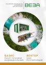
Каталог продукции Веза 2025 - Пункт тепловой индивидуальный БАЗИС, узел регулирующий ВЕКТОР. pdf, 8.85 Mb
Каталог индивидуальных тепловых пунктов БАЗИС, узлов регулирующих ВЕКТОР и блочных тепловых пунктов: назначение, схемы, комплектация, технические характеристики, габаритные размеры. -
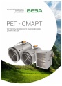
Каталог продукции Веза 2024 - Регуляторы переменного расхода воздуха РЕГ-СМАРТ для VAV-систем. pdf, 1.83 Mb
Каталог регуляторов переменного расхода воздуха РЕГ-СМАРТ для VAV-систем: назначение, конструкция, исполнения, технические характеристики, габаритные размеры, обозначение при заказе. -
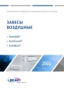
Каталог продукции Веза 2025 - Воздушные завесы. pdf, 4.97 Mb
Каталог воздушных завес Веза AeroWall, AeroGuard, AeroBlast: назначение, конструкция и исполнения, технические характеристики, габаритные размеры, подбор.
Новое в инструкциях
-
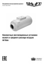
Компактные приточные установки Shuft серии AirTube. pdf, 350.53 Kb
Модели: AirTube 160, 200, 250, 315. Паспорт (объединённый эксплуатационный документ): описание устройства, монтаж, подключение электропитания, схемы электрических соединений, обслуживание, поиск и устранение неисправностей, гарантия, технические данные. -
Приточные установки Shuft серии Eco-Slim. pdf, 8.64 Mb
Модели: Eco-Slim 350, 700, 1100, 1100 W. Паспорт (объединённый эксплуатационный документ) установок с электрическим и водяным нагревателем: технические характеристики, монтаж, схема электрического подключения, обслуживание, пульт управления «Oazis», неисправности. -
Канальные фанкойлы Shuft серии SFF. pdf, 1.91 Mb
Модели: SFF-200G50 … SFF-1400G50. Инструкция по эксплуатации средненапорных канальных фанкойлов: внешние виды и размеры, технические характеристики, монтаж, электропроводка, техническое обслуживание, устранение неисправностей.