

Инструкция на Полупромышленные и промышленные кондиционеры MDV (сервис мануалы)
Сплит - системы MDV серии DC INVERTER (LIS-B-1411). Сервис мануал 2014.
Смотрите также: Коды ошибок →
Загружаем документ…
Текст инструкции
-
DC INVERTER SERIES
Service Manual 2014 LIS-B-1411
-
Indoor Units
Part 2 Indoor Units New Four-way Cassette Type (Compact) Super Slim Cassette Type Duct Type 8 Indoor Units
-
1. Feature
es 1.1 New pa anel 360°surrrounding air outlet desig gn, affords ccomfortable feeling f 1.2 Compa act design The bod dy size is 570×260×57 5 70mm, it’s jjust smallerr than the ceiling c boarrd, so it’s very v easy for f installatio on and will not n damage the decorattion. The panel size is…
-
2 Dimens sions MDCA3-12HRDN1 Gas side Body Drain hole ( for Service ) Wiring connection port E-parts box 2- 150 Distribution duct 2- 4-Screw hole (for install panel) 4-install hanger Drain pipe 65 Fresh air intake Wiring connection port 42 68 Panel 647 Liquid side MDCA3-18HRDN1
-
3 Service e Space 14 4
-
4 Wiring Diagram ms MDCA3-12HRDN1 MDCA3-18HRDN1 16
-
Airr Velocity and Temperature Distributions(R
Reference Data) ta) 5. 5 Air Velo ocity and d Tempe erature D Distributio ons(Referrence Data Airflow vvelocity Temperatture 17
-
Electric Characcteristics
-
Accessoriies
8. 8 Access sories Name Installation fitttings Drainpipe Fittings Remote contrroller & Its holder Shape Quantity 1. Expansible hook 4 2. Installattion hook 4 3. Installattion paper boa ard 1 4. Out-let pipe sheath 1 5. Out-let pipe clasp 1 6. Tightening band 20 7. Drain jo oint 1 8. Remote e…
-
MDCA3-12HRDN1
MDCA3-18HRDN1 21
-
1. Features
1.1 Overview Compact design, super slim body size, less space requiring in installation Each louver can be separately controlled, more comfort air blowing is possible. Auto-lifting panel design, more convenient to clean and maintain the filter. (optional) 18K-24K 30K 36K-48K 60K Old Cassette…
-
Featurres
New air-inta ake 1.3 Optiona al ionizer generator g r Ionizer g generator is optional to get g refreshin ng air to you ur room. Ionizer generator conne ector Ventilation motor connecctor Ionizer ccan be switched on or offf by remote e controller. When prressing the Clean C Air bu utton on the…
-
1.4 Extern
nal air duct design Reserve e external a duct, morre flexible fo air or the air sup pply. n draining g pump 1.5 Built-in Due to th he improvem ment of struc cture, more convenient to repair or replace the draining pump. Draining Pump 30 0 Built-in d draining pum mp to make sure s conden nsed…
-
Featurres
1.6 Termina als for alarm lamp and a long-d distance on-off o conttroller con nnection are a standarrd Reserve e terminals for f the conn nection of allarm lamp and a long-distance on-offf controller, more huma an control. Ala arm lamp Lon ng-distance on-off controoller 1.7 Option nal touch screen…
-
2. Dimensions
Model 18-30 36-48 60 32 A H >235 >275 >317 Super Slim Cassette Type
-
Super Slim Cassette Type
-
MDCD-18HRDN1
MDCD-24HRDN1 MDCD-36HRDN1 MDCD-48HRDN1 MDCD-60HRDN1 34 Super Slim Cassette Type
-
Air Velocity and Temperature Distributions(Reference Data)
5. Air Velocity and Temperature Distributions(Reference Data) Airflow velocity Condenser Evaporator Electronic Condenser temp. sensor expansion valve High pressure switch Evaporator temp. sensor T2 T3 Filter Capillary Filter T1 Room temp. sensor T5 Discharge temp. sensor Oil separator T4 Ambient…
-
Electric Characteristics
6. Electric Characteristics Indoor Unit Model MDCD-18HRDN1 MDCD-24HRDN1 MDCD-30HRDN1 MDCD-36HRDN1 MDCD-48HRDN1 MDCD-60HRDN1 Hz Voltage 220-240 220-240 220-240 220-240 220-240 220-240 Min Max Power Supply MFA Note: MFA: Max. Fuse Amps. (A) 36 Super Slim Cassette Type
-
Sound Levels
7. Sound Levels 1.4m Microphone Model MDCD-18HRDN1 MDCD-24HRDN1 MDCD-30HRDN1 MDCD-36HRDN1 MDCD-48HRDN1 MDCD-60HRDN1 Super Slim Cassette Type Noise level dB(A) H M L
-
Accessories
8. Accessories Name INSTALLATION FITTINGS Tubing & Fittings Drainpipe Fittings Remote controller & Its Frame Others Installation accessory (The product you have might not be provided the following accessories 38 Shape Quantity Installation paper board 1 Bolt M5 4 Soundproof / insulation sheath 2…
-
The Speciffication of Pow
-
Super Slim Cassette Type
-
D
Type 1. Feature es 1.1 Installa ation accessories: (Optional) Front Bo oard, Canvass Air Passag ge, Filter, Pa anel, for eas sy installation Front Board d Canva as Air Passa age Filter Pannel 1.2 Easy In nstallation n: Two air inlet style es (Bottom m side or Rear R side) Air inlet ffrom rear…
-
Duct Tyype
Replace the motor or o centrifuga al fan Remove e the ventila ated panel firstly. f Remo ove a half of o blower ho ousing and take out th he motor wiith gal fan. Direcctly remove two bolts, a and then replace the motor or centriffugal fan ea asily. centrifug Motor Blower Hou using Ventilated Panel…
-
750mm upmost
Duct D Type 1.7 Built-in n display board b The stan ndard indoorr unit can be e controlled by wired controller. There is a display bo oard with a receiver r in th he E-box. Move out the display, andd fix it in othe er place, eve en in the disstance of 10 0m. The unit will realized d remoter co…
-
B
-
3. Service Space
Ensure enough space required for installation and maintenance. All the indoor units reserve the hole to joint the fresh air pipe. The hole size as following: 46 Duct Type
-
MDTB1-12HWDN1
MDTB1-12HWDN1(B) Duct Type 47
-
MDTB-18HWDN1
MDTB-24HWDN1 MDTB-36HWDN1 MDTB-48HWDN1 48 MDTB-60HWDN1 Duct Type
-
5. Static Pressure
Air flow rate (m3/h) 12K External static pressure (Pa) 18K Air flow rate (m3/h) 1200 1000 External static pressure (Pa) 24K 1600 Air flow rate (m3/h) 1400 1200 1000 External static pressure (Pa) Duct Type 49
-
36K
Air flow rate (m3/h) 2500 2000 1500 1000 External static pressure (Pa) 48K Air flow rate (m3/h) 3000 2500 2000 1500 1000 External static pressure (Pa) 60K 3000 Air flow rate (m3/h) 2500 2000 1500 1000 External static pressure (Pa) 50 Duct Type
-
6. Electric Characteristics
Model Indoor Unit Power Supply Hz Voltage Min. Max. MFA MDTB1-12HWDN1 50 220-240 MDTB1-12HWDN1(B) 50 220-240 198 254 / MDTB-18HWDN1 50 220-240 MDTB-24HWDN1 50 220-240 MDTB-36HWDN1 50 220-240 MDTB-48HWDN1 50 220-240 MDTB-60HWDN1 50 220-240 Note: MFA: Max. Fuse Amps. (A) Duct Type 51
-
Concealed Duct Type
Discharge Suction Duct Duct 1.4m Microphone Model MDTB1-12HWDN1 52 Noise level dB(A) H M L MDTB1-12HWDN1(B) MDTB-18HWDN1 MDTB-24HWDN1 MDTB-36HWDN1 MDTB-48HWDN1 MDTB-60HWDN1 Duct Type
-
Duct Tyype
8. 8 Accessories Name Shaape Quantity y So oundproof / inssulation sheatth 2 Bin nding tape 1 Se eal sponge 1 Drrain joint 1 Se eal ring 1 Wired controllerr 1 Ow wner,s manua al 1 Ins stallation man nual 1 Ma agnetic ring (tw twist the electrric wires L an nd N around it to five circles) 1 Tubing &…
-
D
-
For model 18-60
56 Duct Type
-
1. Dimensions
Model Unit:mm A B C D E F H MDOU-12HDN1 MDOU-18HDN1 MDOZU-12HDN1 MDOU-18HFN1 MDOU-24HDN1 MDOU-36HDN1 Outdoor Units
-
Model
-
MDOU-60HDN1
-
2. Service Space
(Wall or obstacle) Air inlet More than 30cm Air inlet More than 60cm Maintain channel More than 60cm Air outlet Outdoor Units More than 30cm More than 200cm 127
-
3. Piping Diagrams
MDOU-12HDN1 MDOZU-12HDN1 INDOOR OUTDOOR CHECK VALVE (Heating Model only) LIQUID SIDE 2-WAY VALVE T3 Condenser temp. sensor CAPILIARY TUBE HEAT EXCHANGE (EVAPORATOR) HEAT EXCHANGE (CONDENSER) T4 Ambient temp. sensor T1 Room temp. sensor T2 Evaporator temp. sensor GAS SIDE 3-WAY VALVE 4-WAY VALVE…
-
MDOU-18HDN1 MDOU-18HFN1
INDOOR MDOU-24HDN1(220075301400) OUTDOOR CAPILIARY TUBE LIQUID SIDE Electronic expansion valve 2-WAY VALVE T3 Condenser temp. sensor HEAT EXCHANGE (EVAPORATOR) T2 Evaporator temp. sensor middle T2B Evaporator temp. sensor outlet HEAT EXCHANGE (CONDENSER) T4 Ambient temp. sensor T1 Room temp. sensor…
-
MDOU-36HDN1
INDOOR OUTDOOR CAPILIARY TUBE LIQUID SIDE Electronic expansion valve 2-WAY VALVE HEAT EXCHANGE (EVAPORATOR) T3 Condenser temp. sensor T2B Evaporator temp. sensor outlet GAS SIDE 3-WAY VALVE 4-WAY VALVE Accumulator High pressure switch T5 Discharge temp. sensor Oil separator Compressor Low pressure…
-
MDOU-12HDN1
Outdoor Units 131
-
MDOZU-12HDN1
MDOU-18HDN1 132 Outdoor Units
-
MDOU-18HFN1
Outdoor Units 133
-
MDOU-24HDN1 (220075301400)
MDOU-24HDN1 (220075302030) 134 Outdoor Units
-
MDOU-36HDN1
Outdoor Units 137
-
MDOU-48HDN1
MDOU-60HDN1 MDOU-48HDN1 MDOU-60HDN1 (New Body) 138 Outdoor Units
-
Electric Characteristics
5. Electric Characteristics Hz Voltage Min. Max. Power Supply MFA MDOU-12HDN1 50 220-240 198 254 / MDOU-18HDN1 50 220-240 198 254 / Outdoor Unit Model MDOZU-12HDN1 50 220-240 MDOU-18HFN1 50 220-240 MDOU-24HDN1 50 220-240 MDOU-36HDN1 50 380-420 MDOU-48HDN1 50 380-420 MDOU-60HDN1 50 380-420 Note: MFA…
-
Operation Limits
6. Operation Limits Temperature Mode Room temperature Cooling operation Heating operation Drying operation 17℃~32℃ 0℃~30℃ 17℃~32℃ -15℃~24℃ 0℃~50℃ 0℃~50℃ Outdoor temperature (-15℃~50℃:For the models with low temperature cooling system) CAUTION: 1. If the air conditioner is used beyond the above…
-
Sound Levels
7. Sound Levels Outdoor Unit Microphone H 1.0m Note: H= 0.5 × height of outdoor unit Model Noise level dB(A) H MDOU-12HDN1 48 MDOZU-12HDN1 57 MDOU-18HDN1 51 MDOU-18HFN1 57 MDOU-24HDN1 (220075301400) 54 MDOU-24HDN1 (220075301401) 59 MDOU-24HDN1 (220075302030) 55 MDOU-36HDN1 63 MDOU-48HDN1 62…
-
Installation Procedure
1. Installation Procedure Indoor unit installation location selection Outdoor unit installation location selection Indoor unit installation Outdoor unit installation Refrigerant pipe installation and insulation Refrigerant pipe installation and insulation Drainage pipe installation and insulation…
-
Location selection
2. Location selection 2.1 Indoor unit location selection The place shall easily support the indoor unit’s weight. The place can ensure the indoor unit installation and inspection. The place can ensure the indoor unit horizontally installed. The place shall allow easy water drainage. The…
-
3. Indoor unit installation
3.1 Compact cassette indoor unit installation 3.1.1 Service space for indoor unit 3.1.2 Bolt pitch 3.1.3 Install the installation hooks. (Use either a M8 or M10 size bolt. ) Use expansible hooks, sunken anchors or other field supplied parts to reinforce the ceiling in order to bear the weight of the…
-
allation
. 3.1.4 Install the main body b Make M the 4 ssuspender th hrough the 4 hanger of the main bo ody to suspe end it. Adjusst the hexan ngular nuts on o th he four insta allation hookks evenly, to ensure the balance of the t body. Us se a levelingg instrument to make sure th he levelnesss of the main n…
-
Hang the panel to the hooks on the mainbody
Tighten the screws under the panel hooks till the panel closely stick on the ceiling to avoid condensate water. Hang the air-in grill to the panel, then connect the lead terminator of the swing motor and that of the control box with corresponding terminators on the body respectively. Note: The panel…
-
3.2 Big cassette indoor unit installation
3.2.1 Service space for indoor unit Model 18 24 30-60 A H >260 >260 >330 3.2.2 Bolt pitch 3.2.3 Install the pendant bolt Select the position of installation hooks according to the hook holes positions showed in upper picture. 148 Installation
-
Drill
D four holles of Ø12m mm, 45~50mm deep a at the selec cted position ns on the cceiling. Then embed th he expansible ho ooks (fittingss). 3.2.4 Install the main body b Make M the 4 ssuspender th hrough the 4 hanger of the main bo ody to suspe end it. Adjusst the hexan ngular nuts on o th he four…
-
3.2.5 Install the panel
Remove the grille Remove the 4 corner covers. Hang the panel to the hooks on the mainbody. 150 Installation
-
Tighten the screws under the panel hooks till the panel closely stick on the ceiling to avoid condensate water. Hang the air-in grill to the panel, then connect the lead terminator of the swing motor and that of the control box with corresponding terminators on the body respectively. Install the 4…
-
3.3 A5 duct indoor unit installation
3.3.1 Service space for indoor unit 3.3.2 Bolt pitch Capacity(KBtu) Size of outline dimension mounted plug L M 30/36 1180 490 48/60 1240 500 3.3.3 Install the pendant bolt Select the position of installation hooks according to the hook holes positions showed in upper picture. Drill four holes of…
-
3.3.4 Install the main body
b Make M the 4 ssuspender th hrough the 4 hanger of the main bo ody to suspe end it. Adjusst the hexan ngular nuts on o th he four insta allation hookks evenly, to ensure the balance of the t body. Us se a levelingg instrument to make sure th he levelnesss of the main n body is witthin ±1°. er 3.3.5…
-
3.3.7 Change the air inlet direction
① Take off ventilation panel and flange, cut off the staples at side rail. ② Stick the attached seal sponge as per the indicating place in the following fig, and then change the mounting positions of air return panel and air return flange . ③ When install the filter mesh, please plug it into flange…
-
3.4 HESP duct indoor unit installation
3.4.1 Service space for indoor unit 500mm or more 600mm or more Indoor unit Maintenance and repair space 600mmx600mm 3.4.2 Bolt pitch MHD: MHG: Installation 155
-
allation
Capacity (KBtu) 36 48~60 Size o of mounted lug D 397 495 E 1146 1236 3.4.3 Install the pendan nt bolt Select S the po osition of insstallation hoo oks accordin ng to the hoo ok holes pos sitions show wed in upperr picture. Drill D four holles of Ø12m mm, 45~50mm deep a at the selec cted position ns…
-
3 Ceiling g & floor in ndoor unitt installati on 3.5.1 Servic ce space forr indoor unit 3.5.2 Bolt piitch ① Ceiling insstallation ② Floor stan nding installa ation In nstallation 157
-
allation
3.5.3 Install the pendan nt bolt ① Ceiling insstallation Select S the po osition of insstallation hoo oks accordin ng to the hoo ok holes pos sitions show wed in upperr picture. Drill D four holles of Ø12m mm, 45~50mm deep a at the selec cted position ns on the cceiling. Then embed th he expansible…
-
Hang the unit on the hanging arm by sliding backward. Securely tighten the mounting bolts on both sides. (some of the models 60 do not do this) For some of the models 60 please securely tighten the mounting bolts on both sides. Then install the side panels and grilles back to the main unit. ② Floor…
-
allation
3.6 3 Consolle indoor unit u installlation 3.6.1 Servic ce space forr indoor unit b 3.6.2 Install the main body Fix the h hook with tap pping screw w onto the wa all Hang the e indoor unitt on the hoo ok. (T The bottom of body can touch with floor or susp pended, but the body must install…
-
3.7 Super slim cassette indoor unit installation
3.7.1 Service space for indoor unit Model 18-30 36-48 60 A H >235 >275 >317 3.7.2 Bolt pitch 3.7.3 Install the pendant bolt Select the position of installation hooks according to the hook holes positions showed in upper picture. Drill four holes of Ø12mm, 45~50mm deep at the selected positions on…
-
allation
3.7.4 Install the main body b Make M the 4 ssuspender th hrough the 4 hanger of the main bo ody to suspe end it. Adjusst the hexan ngular nuts on o th he four insta allation hookks evenly, to ensure the balance of the t body. Us se a levelingg instrument to make sure th he levelnesss of the main n…
-
Remove the 4 corner covers
Hang the panel to the hooks on the mainbody. If the panel is with auto-lift grille, please watch the ropes lifing the grille, DO NOT make the ropes enwinded or blocked. Tighten the screws under the panel hooks till the panel closely stick on the ceiling to avoid condensate water. Installation 163
-
Hang the air-in grill to the panel, then connect the lead terminator of the swing motor and that of the control box with corresponding terminators on the body respectively. Install the 4 corner covers back. Note: The panel shall be installed after the wiring connected. 164 Installation
-
3.8 GA floor standing indoor unit installation
3.8.1 Service space for indoor unit a. A place which provides the spaces around the indoor unit as required above in the diagram. b. A place where is no obstacle near the inlet and outlet area. c. A place which can bear the weight of the indoor unit. d. A place which allows the air filter to be…
-
3.8.2.2. Dismounting the lower front panel
Please take off the lower front panel before connecting the pipes/wires. Pull down the two knobs on the grille, take off the two screws, then the air-inlet grille goes free. 3.8.2.3. Take the Pipe Clip off before connecting the pipes and wiring; fit it when these finished. Use accessories to connect…
-
3.9 3rd generation ceiling & floor indoor unit installation
3.9.1 Service space for indoor unit 3.9.2 Bolt pitch ① Ceiling installation Capacity (Btu/h) D E 18K, 24K 983 220 36K 1200 220 48K, 60K 1565 220 ② Wall-mounted installation 3.9.3 Install the pendant bolt Installation 167
-
allation
① Ceiling insstallation Select S the po osition of insstallation hoo oks accordin ng to the hoo ok holes pos sitions show wed in upperr picture. Drill D four holles of Ø12m mm, 45~50mm deep a at the selec cted position ns on the cceiling. Then embed th he expansible ho ooks (fittingss). ② Wall-moun…
-
Put the side panels and grilles back
② Wall-mounted installation Hang the indoor unit by insert the tapping screws into the hanging arms on the main unit. (The bottom of body can touch with floor or suspended, but the body must install vertically.) Installation 169
-
Outdoor unit installation (Side Discharge Unit)
4. Outdoor unit installation (Side Discharge Unit) 4.1 Service space for outdoor unit (Wall or obstacle) Air inlet More than 30cm More than 30cm More than 60cm Maintain channel Air inlet More than 60cm Air outlet More than 200cm 4.2 Bolt pitch Model 12K 12K(W190) 18K 18K(W190) 24K 30K 36K 48K 60K…
-
5. Refrigerant pipe installation
5.1 Maximum pipe length and height drop Considering the allowable pipe length and height drop to decide the installation position. Make sure the distance and height drop between indoor and outdoor unit not exceeded the date in the following table. Model 12,000Btu/h Max. Length 25m Max. Elevation 10m…
-
Pipe diameter
Flare dimension A (mm) Min Max 1/4" (6.35) 8.3 8.7 3/8" (9.52) 12.0 12.4 1/2" (12.7) 15.4 15.8 5/8" (15.9) 18.6 19.1 3/4" (19) 22.9 23.3 Flare shape +- 4 90° 45° A R0.4~0.8 After flared the pipe, the opening part must be seal by end cover or adhesive tape to avoid duct or exogenous impurity come…
-
Drop
Height Pipe Length Note: All used branch pipe must be produced by Midea, otherwise it causes malfunction. The indoor units should be installed equivalently at the both side of the U type branch pipe. Total pipe length (Actual) Max. branch pipe length Max. branch pipe length difference Max. height…
-
Installation
-
Additional refrigerant charge
8. Additional refrigerant charge After the vacuum drying process is carried out, the additional refrigerant charge process need to be performed. The outdoor unit is factory charged with refrigerant. The additional refrigerant charge volume is decided by the diameter and length of the liquid pipe…
-
Electrical Control System
Part 5 Electrical Control System 1. Electrical Control Function 185 2. Troubleshooting 202 3. Controller 235 184 Electrical Control System
-
1. Electrical Control Function
1.1 Definition T1: Indoor room temperature T2: Coil temperature of indoor heat exchanger middle. T2B: Coil temperature of indoor heat exchanger outlet. T3: Coil temperature of condenser T4: Outdoor ambient temperature T5: Compressor discharge temperature Td: Target temperature 1.2 Main Protection…
-
1.3 Operation Modes and Functions
1.3.1 Fan mode (1) Outdoor fan and compressor stop. (2) Temperature setting function is disabled, and no setting temperature is displayed. (3) Indoor fan can be set to high/(med)/low/auto. (4) The louver operates same as in cooling mode. (5) Auto fan: For MDCA2-12HRDN1: T1 27 High 25 Low For GA…
-
For other models
T1-24 5.0 High 4.0 Medium 3.0 2.0 Low 1.3.2 Cooling Mode 1.3.2.1 Outdoor fan running rules For 12k models: High 22 20 Low For other models: High Low 15 low temperature cooling Outdoor fan in low temperature cooling mode acts as follow: T3 38 Exit low temperature cooling mode, High fan running for 1…
-
MDOU-18HFN1
T4 28℃ A DC_FAN_HI_SPD_ADD B DC_FAN_MID_SPD_ADD C DC_FAN_MIN_SPD_ADD D DC_FAN_SLOW_SPD_ADD E DC_FAN_SSLOW_SPD_ADD 26℃ 25℃ 23℃ 22℃ 20℃ 19℃ 17℃ 1.3.2.2 Indoor fan running rules In cooling mode, indoor fan runs all the time and the speed can be selected as high, (medium), low and auto. The auto fan…
-
T1-Ts
-
---0℃≤T2<4℃, the compressor frequency will be limited and decreased to the lower level every 1 minute till off. ---4℃≤T2≤7℃, the compressor will keep the current frequency. ---T2>7℃, the compressor frequency will not be limited. For other models: When T2<2℃ and lasts for 3 minutes, the indoor has no…
-
T4
21℃ E DC_FAN_SSLOW_SPD_ADD D DC_FAN_SLOW_SPD_ADD C DC_FAN_MIN_SPD_ADD B DC_FAN_MID_SPD_ADD A DC_FAN_HI_SPD_ADD 19℃ 18℃ 16℃ 15℃ 13℃ 12℃ 10℃ For other models: 14 Low 12 High 1.3.3.2 Indoor fan running rules: When the compressor is on, the indoor fan can be set to high/(med)/low/auto. And the anti-cold…
-
T1-TS-∆T
-3 High -2 Low For MDUB-12HRDN1 & MDTB1-12HWDN1: T1-Ts+(6-∆T) Low 2.5 2 Medium 1.5 1 High For MDFA-12HRDN1: T1-Ts-∆T Low 2.5 2 Medium 1.5 1 High For MDCA3-12HRDN1, MDTB1-12HWDN1, MDFA-12HRFN1: T1-Td Low -0.5 -1.5 Medium -2.5 -3.5 High For other models: 192 Electrical Control System
-
T1-Ts
Low -2 -3 Medium -4 -5 High 1.3.3.4 Defrosting mode: For 12k models(Excluding MDOU-12HDN1): Condition of defrosting: ----T4>0℃, Defrosting starts when either of the following ①&②: ② The units run with T3<3℃ for 40 minutes and T3 keeps lower than TCDI℃ for more than 3 minutes. ②:The units run with…
-
on
Compressor no longer than 10min 60s 10s F8 F2 30s off 4-way valve on off Outdoor fan on Off Indoor fan on off breeze 10s For 18-36K(1-Phase) models(Excluding MDOU-18HFN1): Condition of defrosting: T3≤TempEnterDefrost_ADD ℃ and lasts for 40 minutes. Defrosting action: 4-Way valve no longer than 10min…
-
T4
Time1 3℃ Time2 Time conditions: time1 Time conditions(Meet the following conditions) 1.Running in heating mode 2. T4≥3℃ 3. Compressor is on 4. T3≤TempEnterDefrost_ADD ℃ Cleared conditions (Meet any one of the following conditions) 1. Compressor is off. 2. T3>TempEnterDefrost_ADD ℃ Time2 Time…
-
4-Way valve
no longer than 10min Compressor Indoor fan TimeA 10S 10S 30S Outdoor fan PMV running 8 mins with 300P PMV 480P Condition of ending defrosting: If any one of following items is satisfied, defrosting will stop and the machine will turn to normal heating mode. ① The defrosting time achieves 10min; ② T3…
-
no longer than 10min
Compressor X1 10S X2 10S 4-Way valve Outdoor fan 1.3.3.5 High evaporator coil temp.T2 protection: For 12k models(Excluding MDCA3-12HRDN1, MDTB1-12HWDN1,MDFA-12HRFN1) : ----T2> TEH2℃, the compressor running frequency decreases to the lower level every 20s. When the frequency decreases to F2 and the…
-
For other models
∆T=T1-Ts Running mode ∆T≥2℃ Cooling -1≤∆T<2℃ Fan-only ∆T<-1℃ Heating Indoor fan will run at auto fan of the relevant mode. The louver operates same as in relevant mode. If the machine switches mode between heating and cooling, the compressor will keep stopping for 15 minutes and then choose mode…
-
1.3.7 Economy function
For 12k models(Excluding MDCA3-12HRDN1, MDTB1-12HWDN1,MDFA-12HRFN1): 1.3.7.1 The sleep function is available in cooling, heating or auto mode. 1.3.7.2. Operation process in sleep mode is as follow: When cooling, the setting temperature rises 1℃ (be lower than 30℃) every one hour, 2 hours later the…
-
The indoor unit is equipped with auto-restart function, which is carried out through an auto-restart module. In case of a sudden power failure, the module memorizes the setting conditions before the power failure. The unit will resume the previous operation setting automatically after 3 minutes when…
-
The frequency after the frequency limit 05 The frequency of sending to 341 06 Indoor unit evaporator outlet temp.(T2) 07 Condenser pipe temp.(T3) 08 Outdoor ambient temp.(T4) 09 Compressor discharge temp.(Tp) 10 AD value of current 11 AD value of voltage 12 Indoor unit running mode code 13 Outdoor…
-
g
2. 2 Troub bleshootting 2.1 2 Display y board 2.1.1 Icon exxplanation on n indoor disp play board ((Big cassette e). 2.1.2 Icon exxplanation on n indoor disp play board ((Compact ca assette & High static preessure Duct(MHD).) n indoor disp play board ((Ceiling & flo oor) 2.1.3 Icon exxplanation on n…
-
2.1.5 Icon exxplanation on
n indoor disp play board ((Console) uto-lifting pa anel of 4 wayy cassette 2.1.6 Displayy board of au A floor stand ding 2.1.7 Displayy board of GA Electrical Contrrol System 2 203
-
2.1.8 Icon explanation on indoor display board (3rd generation ceiling & floor)
204 Electrical Control System
-
2.2 Indoor unit malfunction
-
For MDFA-12HRDN1
NO. Malfunction Running lamp Timer lamp Defrosting lamp 1 Communication malfunction between indoor and outdoor units. X ☆ X 2 Open or short circuit of T1 temperature sensor ☆ X X 3 Open or short circuit of T2 temperature sensor X X ☆ 4 Indoor EEPROM malfunction ☆ ☆ X 5 IPM module protection ☆ X ☆ 6…
-
For Normal 4-way cassette(24K-30K)
-
For Super-slim 4-way Cassette & MDCA3-18HRDN1
-
For MDCA3-12HRDN1, MDTB1-12HWDN1,MDFA-12HRFN1
Operation Timer lamp Display LED STATUS lamp ☆ 1 time X E0 ☆ 2 times X E1 ☆ 4 times X E3 ☆ 5 times X E4 ☆ 6 times X E5 ☆ 7 times X EC Refrigerant leakage detection ☆ 8 times X EE Water-level alarm malfunction ☆ 2 times O F1 ☆ 3 times O F2 ☆ 4 times O F3 ☆ 5 times O F4 Outdoor unit EEPROM error ☆ 1…
-
Inverter compressor drive error ☆ O P4 8 Communication malfunction between main control board and driver board ☆ ☆ P4 O(light) X(off) ☆(flash at 2.5Hz) 18~60k Display Malfunction or Protection E0 Outdoor EEPROM malfunction E2 Communication malfunction between indoor and outdoor units. E3…
-
2.4 Solving steps for typical malfunction
2.4.1 For the indoor unit 2.4.1.1 Open or short circuit of temperature sensor Check the connections between temperature sensor and PCB. Are the connections good? No Correct the connections. Yes Measure the resistance value of the sensor via Appendix 1 Is it normal? No Replace the sensor. Yes Replace…
-
2.4.1.3. Indoor EEPROM malfunction
EEPROM: An electrically erasable programmable read-only memory whose contents can be erased and reprogrammed using a pulsed voltage. 2.4.1.4. Water-level alarm malfunction 212 Electrical Control System
-
2.4.1.5. Indoor fan Speed has been out of control.(Only for console 12k)
Index 1: 1. Indoor DC fan motor(control chip is inside fan motor) Power on and when the unit is in standby, measure the voltage of pin1-pin3, pin4-pin3 in fan motor connector. If the value of the voltage is not in the range showing in below table, the PCB must have problems and need to be replaced.…
-
2.4.1.6. Inverter compressor drive protection (Only for compact cassette 12k & console 12k)
Refer to the outdoor unit P6 malfunction part to solve this problem. 2.4.1.7 Communication malfunction between indoor and outdoor units. The same as E2 in outdoor. 2.4.2 For the super-slim cassette with up-down panel 2.4.2.1 Communication error between indoor unit and up-down panel 2.4.2.2 Up-down…
-
2.4.3 For the unit with TWINS function(For the super-slim cassette & A5 duct)
2.4.3.1 Communication malfunction between master unit and indoor unit Electrical Control System 215
-
2.4.3.2 Other malfunction between master unit and indoor unit
One indoor unit displays ”F4”, which means another indoor unit is faulty. Check another indoor unit’s error code and then follow the appropriate solutions to solve the malfunction. 216 Electrical Control System
-
2.4.4 For the outdoor unit
2.4.4.1 IGBT over-strong current protection(Only for 12k) 2.4.4.2. E0 malfunction EEPROM: An electrically erasable programmable read-only memory whose contents can be erased and reprogrammed using a pulsed voltage. Electrical Control System 217
-
2.4.4.3. E2 malfunction(Only for 12k)
Power off, then restart the unit 2 minutes later Yes Measure Vs, is it positive fluctuation? (Vs is the voltage between S and N of outdoor unit. Red pan-S, Black pan-N) No Yes Check the outdoor wiring connection Yes Check the indoor wiring connection Yes Replace the reactor No Check whether reactor…
-
E2 display Communication malfunction between indoor and outdoor units Power off, then restart the unit 2 minutes later Yes Check whether there’s any interference. Such as too many lamps, power transformers? Or the signal wire is too long? Yes Remove interference or add magnet ring on power wire No…
-
2.4.4.5. E3 malfunction
220 Electrical Control System
-
2.4.4.6. E4 malfunction
E4 display Judge 1: Outdoor condenser temp. sensor (T3) is malfunction Check whether the wiring of the condenser temp. sensor(T3) is broken off Yes Connect the wiring well Yes Replace condenser temp. sensor(T3) No Check whether the resistance of condenser temp. sensorT3) is wrong refer to the…
-
2.4.4.7. E5 malfunction
222 Electrical Control System
-
2.4.4.8. E6 malfunction (Only for 36K, 48K with 1 phase)
Electrical Control System 223
-
2.4.4.9. P0 malfunction
224 Electrical Control System
-
Electrical Control System 225
-
P2 display Low pressure protection Whether the wiring between the low pressure protector and main control board is connected well or correctly No Connect it well Yes Whether the low pressure protector is broken Method: Disconnect the plug. Measure the resistance of the low pressure protector. If the…
-
2.4.4.12. P3 malfunction
P3 display Current protection of compressor The protection occurred in standby Yes No Check whether the power voltage is normal. Restart the unit when the power supply gets normal No Yes Measure whether outdoor terminal voltage is normal? No Check the wiring of power wires well or correctly…
-
2.4.4.13. P4 malfunction
When compressor discharge temperature is higher than 115°C, the unit will stop, and unit runs again when compressor discharge temperature is lower than 90°C. 228 Electrical Control System
-
2.4.4.14. P5 malfunction
When condenser high temp. is more than 65°C, the unit will stop, and unit runs again when outdoor pipe temp. less than 52°C. P5 display High temperature protection of condenser Check the connection between temperature sensor and PCB. No No Correct the connection Yes Check whether the condenser…
-
2.4.4.15. P6 malfunction
At first test the resistance between every two ports of U, V, W of IPM and P, N. If any result of them is 0 or close to 0, the IPM is defective. Otherwise, please follow the procedure below: P6 display IPM module protection No Check whether the power voltage is normal. Restart the unit when the…
-
2.4.4.16. P7 malfunction
Electrical Control System 231
-
Appendix 1 Temperature Sensor Resistance Value Table
-
Appendix 2
Unit: ℃---K Discharge temp. sensor table -20 542.7 20 68.66 60 13.59 100 3.702 -19 511.9 21 65.62 -18 483 22 62.73 61 13.11 101 3.595 62 12.65 102 3.492 -17 455.9 23 59.98 63 12.21 103 3.392 -16 430.5 -15 406.7 24 57.37 64 11.79 104 3.296 25 54.89 65 11.38 105 3.203 -14 384.3 26 52.53 66 10.99 106…
-
Appendix 3
Normal voltage of P and N 208-240V(1-phase,3-phase) 380-420V(3-phase) around 310VDC around 530VDC In standby In operation With passive PFC module >200VDC 234 With partial active PFC module >310VDC With fully active PFC module >370VDC / >450VDC Electrical Control System
Схемы, таблицы и рисунки — в просмотре документа выше. Клик по номеру страницы открывает её в просмотре.
Новое в каталогах
-
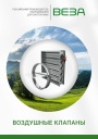
Каталог продукции Веза 2025 - Воздушные клапаны. pdf, 6.71 Mb
Каталог воздушных клапанов Веза: номенклатура, клапаны отсечные и регулирующие РЕГУЛЯР, РЕГУЛЯР-Л, РЕГЛАН, КЕДР и другие — конструкция, исполнения, приводы, технические характеристики, габаритные размеры. -
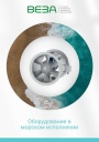
Каталог продукции Веза 2026 - Оборудование в морском исполнении. pdf, 7.62 Mb
Каталог вентиляционного и холодильного оборудования Веза в морском исполнении: радиальные и осевые вентиляторы, кондиционеры КОМПАС-БОВ, компрессорно-конденсаторные агрегаты КОМПАС-ККБ, шкафы управления КОМПАС-ШСАУ — технические характеристики и размеры. -
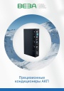
Каталог продукции Веза 2026 - Прецизионные кондиционеры АКП. pdf, 4.90 Mb
Каталог прецизионных кондиционеров АКП: назначение, исполнения, конструкция, технические характеристики, габаритные размеры, обозначение при заказе.
Новое в инструкциях
-
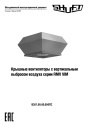
Крышные вентиляторы Shuft серии RMV VIM. pdf, 4.41 Mb
Модели: RMVE 190/300-2 … 450/670-4, RMVD 311/440-4 … 630/950-4 VIM. Паспорт (объединённый эксплуатационный документ): описание, массогабаритные показатели, монтаж, схемы электрических соединений, пуск, обслуживание, гарантийные обязательства, технические данные. -
Вентиляторы в круглом корпусе Shuft серии SH. pdf, 646.47 Kb
Модели: SH 160, 200, 250, 315, 400. Руководство по установке, эксплуатации и техническому обслуживанию: технические характеристики, размеры, монтаж, электрические подключения, ввод в эксплуатацию, обслуживание и чистка, устранение неисправностей. -
Приточно-вытяжные установки Shuft серии NOVA. pdf, 4.29 Mb
Модель NOVA-300. Инструкция по монтажу и обслуживанию: принципиальная схема установки, массогабаритные показатели, монтаж воздуховодов и дренажа, подключение электропитания, схема электрических соединений, пусконаладка, обслуживание, неисправности, подключение к системе диспетчеризации.