

Инструкция на Полупромышленные и промышленные кондиционеры MDV (сервис мануалы)
Сплит-системы MDV серии MDFM колонного типа. Сервис мануал.
Смотрите также: Коды ошибок →
Загружаем документ…
Текст инструкции
-
SERVICE MANUAL
FLOOR STANDING TYPE
-
1 .Safety Precautions
1.1 Precaution To prevent injury to the user or other people and property damage, the following instructions must be followed. Incorrect operation due to ignoring instruction will cause harm or damage. Before service unit, be sure to read this service manual at first. 1.2 Installation For electrical…
-
1.4 Operational
Do not expose the skin directly to cool air for long periods of time. (Do not sit in the draft). Do not use the product for special purposes, such as preserving foods, works of art, etc. It is a consumer air conditioner, not a precision refrigerant system. Do not block the inlet or outlet of air…
-
2 .Dimension
-
2.2 Outdoor Unit
-
3.Refrigerant cycle diagram
MDFM-24ARN1 INDOOR OUTDOOR LIQUID SIDE CHECK VALVE (Heating Model only) 2-WAY VALVE T3 Condenser temp. sensor CAPILIARY TUBE HEAT EXCHANGE (EVAPORATOR) HEAT EXCHANGE (CONDENSER) T1 Room temp. sensor T2 Evaporator temp. sensor GAS SIDE 4-WAY VALVE (Heating Model only) 3-WAY VALVE COOLING COMPRESSOR…
-
MDFM-48ARN1
MDFM-60ARN1 INDOOR OUTDOOR LIQUID SIDE CHECK VALVE (Heating Model only) 2-WAY VALVE T3 Condenser temp. sensor CAPILIARY TUBE HEAT EXCHANGE (EVAPORATOR) HEAT EXCHANGE (CONDENSER) T4 Ambient temp. sensor T1 Room temp. sensor T2 Evaporator temp. sensor GAS SIDE 4-WAY VALVE 3-WAY VALVE Compressor Low…
-
4 . Wiring diagram
MDFM-24ARN1 Indoor unit: Outdoor unit:
-
MDFM-48ARN1
Indoor unit: Outdoor unit:
-
MDFM-60ARN1
Indoor unit: Outdoor unit:
-
5.Installation details
5.1 Installation place 5.1.1 Indoor Unit a. A place which provides the spaces around the indoor unit as required above in the diagram. b. A place where is no obstacle near the inlet and outlet area. c. A place which can bear the weight of the indoor unit. d. A place which allows the air filter to be…
-
avoid hard
wind blows directly to the air outlet, because it may cause trouble for air-flow shortage. 5.1.2.3 Reserve enough space for installation, maintenance and unit-functioning. Remove as many obstacles as possible nearby. 5.2 Installing 5.2.1 Indoor Unit: 1. Anti-falling; To prevent the indoor unit from…
-
The grid is hitched by a loop inside. To dismount the air-inlet grid, hold both sides of the
grid and pull it up, let it slant downwards until the loop become straight. Then removing the screws fastened the loop with the grid, and the grid goes free. 3. Take the pipe clip off before connecting the pipes and wiring; fit it when these finished. Use accessories to connect the pipes/wires on…
-
5. Fix the unit feet with bolts (M10/M8). Be sure the unit is fixed strongly enough to
against blast or earthquake. 6. Make a concrete basement to the unit by the following references. For the value of A and B, please refer to the dimension part. 5.3 Refrigerant pipe connection 5.3.1 Pipe length and the elevation The correct refrigerant quantity filled in the 5-meter-long pipe of the…
-
Caution
Capacity is base on standard length and maximum allowance length is base of reliability. Oil trap should be installed per 5-7 meters. 5.3.2 Piping connection 5.3.2.1 Connecting Of Refrigerant Pipe a) Only the correctly installing of indoor and outdoor unit done, can the refrigerant pipe be…
-
C and D are ends of indoor unit connection. Caution in Handling the Packed Valve a.Open the valve stem until it hits against the stopper. Do not try to open it further. b. Securely tighten the valve stem cap with a spanner or the link. Notes for the bendable pipe a. The bendable pipe should be used…
-
5.3.2.2 Using bronze pipe selling in market
Completely shut the cut-off valves of the outdoor unit (as ex-work status). After the refrigerant pipe has been connected with both the indoor and outdoor unit, let the air exhaust out from the maintenance gap on the low-pressure cut-off valves of the outdoor unit. Screw the nuts tightly on the…
-
5.3.3 Installation for the first time
Air and moisture in the refrigerant system have undesirable effects as below: ● ● ● ● ● Pressure in the system rises. Operating current rises. Cooling or heating efficiency drops. Moisture in the refrigerant circuit may freeze and block capillary tubing. Water may lead to corrosion of parts in the…
-
2) Connect the charge hose with the push pin of handle lo to the 3-way valves gas
service port.. 3) Connect the charge hose of handle hi connection to the vacuum pump. 4) Fully open the handle Lo of the manifold valve. 5) Operate the vacuum pump to evacuate. 6) Make evacuation for 30 minutes and check whether the compound meter indicates ‐0.1Mpa. If the meter does not indicate…
-
1). Confirm that both the 2-way and 3-way valves are set to the closed position
2). Connect the charge set and a charging cylinder to the service port of the 3-way valve. 3). Air purging. Open the valves on the charging cylinder and the charge set. Purge the air by loosening the flare nut on the 2-way valve approximately 45’ for 3 seconds then closing it for 1 minute; repeat 3…
-
1). Connect the charge hose to the charging cylinder, open the 2-way valve and the
3-way valve. Connect the charge hose which you disconnected from the vacuum pump to the valve at the bottom of the cylinder. If the refrigerant is R410A, make the cylinder bottom up to ensure the liquid charge. 2). Purge the air from the charge hose. Open the valve at the bottom of the cylinder and…
-
Electronic scale
Procedure: 1). Connect the charge hose to the 3-way service port, open the 2-way valve and the 3-way valve. Connect the charge hose to the valve at the bottom of the cylinder. If the refrigerant is R410A, make the cylinder bottom up to ensure liquid charge. 2). Purge the air from the charge hose.…
-
Be sure to check for gas leakage
5.3.5 Re-installation while the indoor unit need to be repaired 1. Collecting the refrigerant into the outdoor unit Procedure 1). Confirm that both the 2-way and 3-way valves are set to the opened position Remove the valve stem caps and confirm that the valve stems are in the opened position. Be…
-
Be sure to check for gas leakage
2. Air purging by the refrigerant Procedure: 1). Confirm that both the 2-way and 3-way valves are set to the closed position. 2). Connect the charge set and a charging cylinder to the service port of the 3-way valve Leave the valve on the charging cylinder closed. 3). Air purging. Open the valves on…
-
Be sure to check the gas leakage. 5.3.6 Re-installation while the outdoor unit need to be repaired 1. Evacuation for the whole system Procedure: 1). Confirm that both the 2-way and 3-way valves are set to the opened position. 2). Connect the vacuum pump to 3-way valve’s service port. 3). Evacuation…
-
Electronic scale
Procedure: 1). Connect the charge hose to the charging cylinder, open the 2-way valve and the 3-way valve Connect the charge hose which you disconnected from the vacuum pump to the valve at the bottom of the cylinder. If the refrigerant is R410A, make the cylinder bottom up to ensure liquid charge.…
-
If the system has been charged with liquid refrigerant while operating the air conditioner,
turn off the air conditioner before disconnecting the hose. 6). Mounted the valve stem caps and the service port Use torque wrench to tighten the service port cap to a torque of 18N.m. Be sure to check for gas leakage 5.4 Drain Pipe of The Indoor Unit 1. Make sure the drain pipe is connected to the…
-
Model
Power supply Input Rated Amp (Switch/Fuse) Power Cord Size <24000Btu/h 220-240V~ 50Hz 32/25A ≥2.5mm2 ≥24000Btu/h 220-240V~ 50Hz 63/50A ≥6mm2 ≥24000Btu/h 380-420V~ 50Hz 16/16A ≥1.5mm2 5.6 Test run Perform test operation after completing gas leak and electrical safety check. The test operation time…
-
6.External view and display
6.1 External view This unit consists of indoor unit and outdoor unit. Note: All the pictures in this manual are for explanation purpose only. They may be slightly different from the air conditioner you purchased (depend on model). The actual shape shall prevail.
-
6.2 Control Panel
Control Buttons and Functions
-
7.Operation characteristics
Mode Temperature Cooling operation Heating operation Drying operation Room temperature 17℃~32℃ 0℃~30℃ 17℃~32℃ Outdoor temperature 18℃~43℃ -7℃~24℃ 18℃~ 43℃ CAUTION: 1. If air conditioner is used outside of the above conditions, certain safety protection features may come into operation and cause the…
-
8.Electronic function
8.1 Main data Introduction Ts : Set temperature, T1 : Room temperature T2: Evaporator pipe temperature T3: Condenser pipe temperature T4: Outdoor ambient temperature T5:Compressor discharge temperature 8.2 Main Protection 8.2.1 Time delay for the compressor start-up At the beginning of energizing or…
-
Fan(above)
T4 18 Off 16 On 8.3.1.3 Indoor fan running rules: When the compressor is on, the indoor fan can be set to high/low/auto. And the anti-cold wind function has the priority. Auto fan action: T1-Ts -1 Low -2 High 8.3.1.4 Defrost (only available to heating mode) ---Defrosting Conditions Starting Of…
-
fan motor is off and compressor is on reaches up to over 90 minutes .( Shut down or
defrosting or T3 is over 15°C, calculate time again.) Defrosting Action Four-way valve, indoor fan, outdoor fan are shut down. Compressor keeps on. Ending Of Defrosting Condition (meet one of the following is ok): (1)Time of defrosting lasts 10 minutes. (2) Temperature of outdoor coil T3 is up to…
-
be closed at the first time, the compressor starts under the cooling mode
8.3.2.2 Compressor and outdoor fan running rules Once the compressor starts up, it will follow the below rules: T1-Ts 1 On 0 Off When compressor is on, outdoor fan will follow the below rules:: For single-fan models: The outdoor fan runs all the time. For double-fan models: Fan(below): When…
-
T2
On TE6 TE5 Off When the evaporator coil temp.T2 keeps lower than TE5 for 30 minutes, the compressor and outdoor fan will shut off. When T2 is higher than TE6, the compressor and outdoor fan will restart up. Condition 2: T2 On TE6 TE5-2 Off When the evaporator coil temp.T2 keeps lower than TE5-2 for…
-
When T3≥T3_Pro℃ for 3 seconds, the compressor will shut off. When T3<48℃,the
compressor will restart. 8.3.3 Dehumidifying Mode 8.3.3.1 Indoor fan speed is low. 8.3.3.2 Four-way valve is closed, the compressor and outdoor fan will operate the same as in cooling mode. 8.3.4 Auto Mode 8.3.4.1. Under auto mode, the indoor fan is set to be auto and the temperature is 24°C.…
-
8.4.3.2. Turning off, changing mode or setting fan speed will cancel economy function
8.4.3.3 Operation process in sleep mode is as follow: After pressing ECONOMIC or SLEEP button on the controller, the machine will go into economy mode. When cooling, the setting temperature rises 1℃(be lower than 30℃) every hour, 2 hours later the setting temperature stops rising. For heat pump…
-
9.Trouble shooting
9.1 Self-diagnosis 9.1.1 LEDs for the indication of indoor trouble MDFM-24ARN1 Codes Contents P4 Temperature protection of indoor evaporator P5 Temperature protection of outdoor condenser P9 Anti-cold air(For heat pump models) E1 Open- or short-circuit of T1 temperature sensor E2 Open- or…
-
9.1.2 LEDs for the indication of outdoor trouble (only for 48K-60K)
LED2(green) LED3(yellow) LED4(red) Contents On Off Off OK Off On Off Standby Off Off Flash Lack of phase Off Flash Off Phase sequence error Off Flash Flash Off Off On Open- or short-circuit of T3 temperature sensor Flash Off Off Open- or short-circuit of T4 temperature sensor On Off On Temperature…
-
9.2 Troubles and Solutions
Before calling for service, please review the following list of common problems and solutions. Problem Possible Cause Solutions Air conditioner Power failure Wait for power restoring does not The power supply is disconnected. Switch on the main power switch operate at all The power fuse is blown.…
-
9.2.2 Open or short circuit of temperature sensor(T5)
-
9.2.3 Default phase of compressor
-
9.2.4 Phase sequence error
Phase sequence error Change the order of the wires to power supply. Switch on the unit again. If the problem cannot be solved, the outdoor PCB is defective 9.2.5 High temperature protection of condenser High temperature protection of condenser Check the resistance of the temp. sensor according to…
-
9.2.6 High pressure protection
9.2.7 Low temperature protection Low temperature protection Possible reason 1: The outdoor ambient temp. is low. 2: The wires are loose to the temp. sensor. 3: The temp. sensor is defective. 4: The evaporator or the filter is dirty. 5: System has block. 9.2.8 Low pressure protection Low pressure…
-
9.2.9 Overload of current
-
9.2.10 Communication malfunction between indoor unit and outdoor unit
-
9.2.11 Refrigerant Leakage Detection
-
9.2.12 Temperature protection of compressor discharge
-
Appendix 1 Temperature Sensor Resistance Value Table
-
Appendix 2
Схемы, таблицы и рисунки — в просмотре документа выше. Клик по номеру страницы открывает её в просмотре.
Новое в каталогах
-
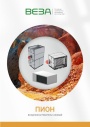
Каталог продукции Веза 2026 - Воздухонагреватели газовые ПИОН. pdf, 6.55 Mb
Каталог газовых воздухонагревателей ПИОН: назначение, конструкция и исполнения, технические характеристики, габаритные размеры, обозначение при заказе. -
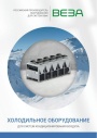
Каталог продукции Веза 2026 - Холодильное оборудование для систем кондиционирования воздуха. pdf, 4.97 Mb
Каталог холодильного оборудования Веза для систем кондиционирования: чиллеры, компрессорно-конденсаторные блоки, фанкойлы и другое оборудование — технические характеристики, габаритные размеры, обозначение при заказе. -
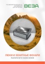
Каталог продукции Веза 2025 - Люки и зенитные фонари различного назначения. pdf, 8.45 Mb
Каталог люков дымоудаления и зенитных фонарей Веза различного назначения: конструкция и исполнения, приводы и автоматика, технические характеристики, габаритные размеры.
Новое в инструкциях
-

Модульные чиллеры с воздушным охлаждением конденсатора Electrolux серии EMACO. pdf, 10.13 Mb
Модели: EMACO-220.V2, EMACO-440.V2. Инструкция по эксплуатации чиллера с воздушным охлаждением конденсатора (модульного блока системы кондиционирования): меры безопасности, технические и эксплуатационные требования, принцип работы, технические характеристики, подъём блока, схема соединения нескольких модулей, вспомогательный электронагреватель, электрическая схема, регулировка и пуск, техническое обслуживание, поиск и устранение неисправностей, инструкция к пульту управления, коды аварийных сигналов, схема подключения внешнего насоса. -

Компрессорно-конденсаторные блоки Shuft серии SDVC. pdf, 5.57 Mb
Модели: SDVC-V03WDHN1, V05WDHN1, V08WDHN1, V10WDHN1, V14WDHN1, V16WDHN1. Инструкция по эксплуатации и руководство по монтажу наружного блока: эксплуатация, обслуживание, диагностика и коды неисправностей, монтаж, трубопроводы хладагента, электроподключение, конфигурация, пробный пуск, технические характеристики. -

Полупромышленные кассетные сплит-системы Shuft серии SFLC_C. pdf, 11.33 Mb
Модели: SFLC_C/in-18…60HN1_V2, SFLC_C/out-18…60HN1_V2, панели SFLC-PC_V2, SFLC-PS_V2. Руководство по эксплуатации: устройство, проводной пульт, монтаж, электрические схемы подключения, размеры, технические характеристики, устранение неисправностей, протоколы приёмки и тестового запуска, гарантийный талон.