

Инструкция на Наружные блоки мини VRF-системы V4+ 22~26kw (сервис мануалы)
Наружные блоки мини VRF-системы V4+ (R410a). Часть 3. Установка. Сервис мануал.
Смотрите также: Сервис мануал →
Загружаем документ…
Текст инструкции
-
1. Precautions
Ensure that all Local, National and International regulations are satisfied. Read this “PRECAUTIONS” carefully before Installation. The precautions described below include the important Items regarding safety. Observe them without fail. After the installation work, perform a trial…
-
Install the air conditioner securely in a location where the base can sustain the weight adequately
Perform the specified installation work to guard against an earthquake. If the air conditioner is not installed appropriately, accidents may occur due to the falling unit. Electrical work must be performed by a qualified electrician in accordance with the Installation Manual. Make sure the air…
-
3. Outdoor unit installation
3.1 Installation space selection Install the outdoor unit at a place where discharge air is not blocked. When an outdoor unit is installed in a place that is always exposed To a strong wind like a coast or on the high store of a building, secure a normal fan operation by using a duct or a wind…
-
Single unit installation
Air inlet > 300 (Wall or obstacle) >300 Maintain the electric wire and pipeline Air inlet >3000 >600 Air outlet Parallel connect two units or above >300 >600 >3000 Parallel connect the front with rear sides >3000 >1000 >6000 >4000 >300 All the pictures in this manual are for explanation purpose…
-
4. Piping installation
4.1 Piping connection Various piping and wiring patterns can be selected, such as out from the front and the side. (The follow display the locations of several piping and wiring knock-off interfaces.) Front out pipe Side out pipe Side out pipe: please remove the L-shape metal plate, otherwise cannot…
-
The first connecting method
Pipe Length(from the nearest branch pipe equivalent length L1 a A Maximum pipe equivalent length The first line Branch Pipe L2 Indoor Unit to Indoor Unit Drop Heihgt Drop HEIGHT between indoor unit and uutdoor unit Outdoor unit (from the first line branch pipe) Maximum pipe equivalent length B L3 b…
-
Outdoor Unit
L1 A L2 L3 B C D c b a f L5 L4 E d e The first Line Branch Pipe The second connecting method Outdoor Unit(Take Model 260 for example) N1 (45) a L1 A L2 B L3 The first Line Branch Pipe intdoor Units b L4 C N2 (45) D L5 c Main pipe The main pipes of indoor unit The branch pipes of indoor unit N4 (45)…
-
A5 duct type 2.2~4.5
12.7(Flaring nut) A5 duct type 5.6~8.0 15.9(Flaring nut) A5 duct type 9.0~14.0 15.9(Flaring nut) Console Type 2.2~4.5 12.7(Flaring nut) Two-way Cassette Type 2.2~4.5 12.7(Flaring nut) Two-way Cassette Type 5.6~7.1 15.9(Flaring nut) Ceiling And Floor Type 3.6~4.5 12.7(Flaring nut) Ceiling And Floor…
-
MCAC-VTSM-2013-03
R410a Full DC Inverter Mini VRF 4.5 Airtight Test Charge pressured nitrogen after connecting indoor/outdoor unit piping to do airtight test. Cautions: 1. 2. 3. 4. 5. 3 Pressured nitrogen [4.3MPa (44kg/cm ) for R410A] should be used in the airtight test. Tighten high pressure/low pressure valves…
-
5. Electric Wiring Installations
5. 1 Highlights of electrical installation 1) Please separately design the special power of indoor units and outdoor units. 2) The power adopts special circuit, and installs creepage protector and manual switch. 3) The indoor units’ power, creepage protector and manual switch connecting to the same…
-
4) The wiring with different voltage should not pass through the same wire tube
5) Total sectional area of wiring through wire tube shall not exceed 40% valid area of stuffing tube. 6) Fixing point of wire tube support shall follow the standard below: Normal diameter of wire tube Largest gap between fixed points of wire tube Mm Metal pipe Plastic pipe 15~20 1.5m 1m 25~32 2m…
-
5.5.5 Indoor unit power wiring selection
Note: 1) Refrigerant piping system, indoor unit-indoor unit connection signal wires and indoor unit-outdoor unit connection signal wire are in the same system. 2) When power cord is parallel with signal wire, please put them into separate wire distribution pipes, and leave a proper distance.…
-
6. Outdoor Unit Wiring
6.1The Specification of Power Table 6-1 Capacity 20~22.4kW 26kW 3 phase 3 phase 380-415V~ 50Hz 380-415V~ 50Hz 5-core X6.0 5-core X6.0 Circuit Breaker/Fuse (A) 30 40 Indoor unit/Outdoor unit Signal wire 2 (Weak electric signal) (mm ) 3-core shielded wire 3X0.75 3-core shielded wire 3X0.75 Outdoor…
-
Wiring the indoor unit and outdoor unit control
CAUTION The reserved function is indicated in broken line table, users can select it when necessary. Indoor/Outdoor Unit Signal Wire Connect the wire according to their numbers. Wrong connection may cause malfunction. Wiring Connection Seal the wiring connection with the insulation material, or the…
-
6.2 Indoor Unit Wiring
Power Supply Table 6-2 Capacity (kW) 1.8~16 Phase indoor Unit power 1- phase Frequency and Voltage 220-240V~ 50Hz 2 Power Wiring(mm ) 3-core×1.0 Circuit Breaker (A) 16 2 Indoor unit/Outdoor unit Signal wire (Weak electric signal) (mm ) 3-core shielded wire 3X0.75 1. Signal wire is 3-core, polarized…
-
Indoor unit power supply wiring
Indoor Power Supply Circuit Breaker Manual swtich Wire Distribution Box Indoor Unit Fig.6-4 CAUTION 1. Refrigerant piping system, indoor unit-indoor unit connection signal wires and indoor unit-outdoor unit connection signal wire are in the same system. 2. When power cord is parallel with signal…
-
7.Test Running
Operate according to “key points for test running” on the electric control box cover. CAUTION Test running cannot start until the outdoor unit has been connected to the power for 12hours. Test running cannot start until all the valves are affirmed open. Never make the test running if the…
-
8.Precautions on Refrigerant Leakage
This air conditioner (A/C) adopts innocuous and nonflammable refrigerant. The locating room of the A/C should big enough that any refrigerant leakage is unable to reach critical thickness. So certain essential action can be taken on time. Refrigerant critical thickness: 0.44[kg/m3] for R410A.…
Схемы, таблицы и рисунки — в просмотре документа выше. Клик по номеру страницы открывает её в просмотре.
Новое в каталогах
-
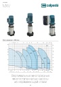
Каталог вертикальных многоступенчатых насосов Calpeda серий MXV, MXVL, MXV EI 2026. pdf, 7.05 Mb
Модели: MXV 25, 32, 40, 50, 65, 80, 100, MXVL 65, 80, MXV EI. Каталог серии: область применения, конструкция и материалы, рабочие характеристики и кривые, габаритные размеры и масса. -

Каталог осевых вентиляторов Shuft серии AXW. pdf, 4.05 Mb
Модели: AXW 4E–8DY с типоразмерами 200–910 в исполнениях S-G, S-T, B-T, B-P. Технический каталог модельного ряда: расшифровка обозначения, характеристики, схемы подключения, аэродинамические графики и габаритные чертежи. -
Каталог продукции Пульсар 2026 - Дренажные насосы. pdf, 3.91 Mb
Каталог продукции Пульсар 2026 - Дренажные насосы
Новое в инструкциях
-

Полупромышленные канальные сплит-системы Shuft серии SFLC_D. pdf, 10.37 Mb
Модели: SFLC_D/in-18…60HN1_V2, SFLC_D/out-18…60HN1_V2. Руководство по эксплуатации: устройство, проводной пульт, монтаж, электрические схемы подключения, размеры, технические характеристики, устранение неисправностей, протоколы приёмки и тестового запуска, гарантийный талон. -

Полупромышленные напольно-потолочные сплит-системы Shuft серии SFLC_CF. pdf, 8.93 Mb
Модели: SFLC_CF/in-18…60HN1_V2, SFLC_CF/out-18…60HN1_V2. Руководство по эксплуатации: устройство, проводной пульт, монтаж, электрические схемы подключения, размеры, технические характеристики, устранение неисправностей, протоколы приёмки и тестового запуска, гарантийный талон. -

Мульти-сплит-системы Shuft серии FMI. pdf, 4.82 Mb
Модели: внутренние блоки SFMS/I-07…18 HB FMI/N8/IN/WHITE, наружные SFMO/I-14…42 FMI-2…5/N8/OUT. Руководство по эксплуатации: технические характеристики, управление кондиционером, монтаж, техническое обслуживание, поиск и устранение неисправностей, возможная комплектация блоков, гарантийный талон.