

Инструкция на VRF-системы V4 (сервис мануалы)
VRF-системы V4. Устранение ошибок P6. Сервис мануал.
Смотрите также: Коды ошибок CCM03 →
Загружаем документ…
Текст инструкции
-
P6 Malfunction Solution
Debugging of P6 Diagram of troubleshooting Current direction confirm Normal inverter modular confirm L0/L8/L9 malfunction troubleshooting L1/L4 malfunction troubleshooting L2 malfunction troubleshooting
-
1. Debugging of P6
P6 protection will displayed 60 seconds then disappear, after that, press the check button 22 times, the digital indicator will display last saved error: • L0 – Modular protection • L1 – Low volt protection of the DC bus bar • L2 – High volt protection of the DC bus bar • L4 – MEC malfunction • L8…
-
P6 Troubleshooting 2. Diagram of troubleshooting
P6 display If P6 occurs 3 times in half hour, digitron will display H4. It will disappear after restart the power supply. L1: Low voltage protection L4: MCE failure Voltage at DC supply wire is lower than 510V check the commutate circuit In normal operation, the current direction runs from N…
-
3. Outdoor control box
Filter capacitors Inverter module Filter circuit board 3 Phase & single phase rectifier stack Compressor capacitors (under the board) PCB Transformers Relays Fixed compressor contactors Wires transfer board Fan motor power terminal Fan motor capacitors Power supply terminal Communication wiring…
-
4. Outdoor PCB
Digital tube (LED display) MCU 9177 EEPROM LED3: Error LED4: Run LED5: Power MCE LED1 & LED2: Inverter module running lights MCU 0034 *MCU: Micro Controller Unit *MCE: Motion Control Engine
-
4. Intelligent Power Module
-
P6 Troubleshooting 5. Current direction confirm
Normal current direction :1→2 → 3 → 4 → 5 → Direction of the current in DC supply wire which is running through the inductor should be the same as the direction of arrow marked on the inductor.
-
6. Normal IPM confirm
N DC voltage between P and N should be about 1.41 times of the local power supply voltage (210V~230V). P First adjust multi -meter to diode position, put the red pen on the 1 point(N terminal), put black pen on the 3 or 4 or 5 point, the value should be approximate 0.378, if the value is 0, the IPM…
-
Step1 Replace the modular with correctly wire connected and start the system, if system is still malfunction, then go to step2 to check the compressor. Step 2
-
Step2
Control box A, took apart from malfunction system. Malfunction estimate: Connect the compressor took apart from malfunction system with control box B, if the compressor could not start normally, that means compressor has been malfunction, or else, control box A has been malfunction. Compressor took…
-
Notice Notice 1 (Beware when doing below): 1.Measure the resistance between each two of U, V, W terminals, all the resistance should be the same and equal to 0.9~5 Ohms. (Fig. A and Fig. B) 2.Measure the resistance between each of U, V, W terminals to ground (Fig. C), all the resistance should be…
-
Step1
1. Check the voltage at DC supply wire, normal is: 510V~580V, if lower than 510V, go to step 2. 2.Check if the wire connection of commutate circuit are loose or not. 3.If all the above are ok, then the PCB malfunction, replace it. 8. L1/L4 troubleshooting
-
Step2
1. Check the voltage at DC supply wire, normal is: 510V~580V, if lower than 510V, go to step 2. 2.Check if the wire connection of commutate circuit are loose or not. 3-Phase commutate bridge Single-Phase commutate bridge Filter board 3.If all the above are ok, then the PCB malfunction, replace it.…
-
Step3
1. Check the voltage at DC supply wire, normal is: 510V~580V, if lower than 510V, go to step 2. 2.Check if the wire connection of commutate circuit are loose or not. 3.If all the above are ok, then the PCB malfunction, replace it. 8. L1/L4 troubleshooting
-
Step1
1. Measure the voltage at DC supply wire, the normal value is: 510V~580V, if higher than 580V, go to step 2. The normal voltage between two electrolytic capacitors is 510V±30V, if not in the range then the PCB has been malfunction, it needs to be replaced. 9. L2 troubleshooting
-
9. L2 troubleshooting
Step2 1. Measure the voltage at DC supply wire, the normal value is: 510V~580V, if higher than 580V, go to step 2. 2. The normal voltage between two electrolytic capacitors is 510V±30V, if not in the range then the PCB has been malfunction, it needs to be replaced. Turn the measure range of the…
-
Case Study
-
Step1. Confirm the PCB chip is correct
And also check the EEPROM serial number. EEPROM Main Chip
-
Step2. Check the inverter modular, after cutting off the power supply,
-
Step3. If inverter modular is normal, then pre-heat the system for 4 hours with all the
indoor units off. By doing this, the refrigerant and the oil could be heating adequately. Step4. Use a screwdriver poking at the relay to force the fixed compressor to start for about 3~5s. Because of the huge start pressure, the impurity in the compressor can be washed away. Step5. After waiting…
-
Step9. Make a Special Compressor
Short-circuit the suction and the discharge of the compressor, vacuum dry and charge 0.3kg~0.4kg R410A. Connect the U,V,W terminals to the control box which is need to be checked. If the compressor could not start, then the PCB has been malfunction, replace it. . Short-circuit the suction and the…
-
Phenomenon A
LED 1 (Green) Flash 8 times and stop for 1s, then repeat Inverter modular malfunction LED 2 (Red) On Malfunction In normal situation: LED 1: Flash in 1Hz (slowly flash) when standby LED 1: On when running LED 2: Off
-
Step1. Measure the voltage between O terminal of CN4 on PCB and ground
CN4 If the voltage is larger than 2.7V, that means PCB has been malfunction and needs to be replaced, but inverter modular is OK If the voltage is lower than 2.7V, that means inverter modular has been malfunction and needs to be replaced. If the voltage is between 2.7V and 2.8V, both PCB and…
-
Phenomenon B
LED 1 (Green) Flash 9 times and stop for 1s, then repeat Low voltage protection LED 2 (Red) On Malfunction There are three situation could cause low voltage protection. 1 The voltage between two electrolytic capacitors is too low (lower than 450V), so that the relay could not draw in (relay draws…
-
Some wire are loose or some spigots are not connected on the inverter modular
-
Phenomenon C (seldom)
LED 1 (Green) Flash 10 times and stop for 1s, then repeat High voltage protection LED 2 (Red) On Malfunction There are two situation could cause low voltage protection. Voltage of the power supply is higher than 440V. PCB has been malfunction, needs to be replaced.
-
For phenomenon 2 and 3, there is a
another way to check: measure the voltage between C37 and ground, if the value equal to 0.6V, then the power supply is ok, PCB has been malfunction, needs to be replaced. Normal voltage: 0.6V
-
C37
Normal voltage: 0.6V
-
Malfunction 3: Frequency jumps irregularly when startup
The troubleshooting is the same as Malfunction1.
Схемы, таблицы и рисунки — в просмотре документа выше. Клик по номеру страницы открывает её в просмотре.
Новое в каталогах
-
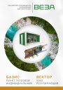
Каталог продукции Веза 2025 - Пункт тепловой индивидуальный БАЗИС, узел регулирующий ВЕКТОР. pdf, 8.85 Mb
Каталог индивидуальных тепловых пунктов БАЗИС, узлов регулирующих ВЕКТОР и блочных тепловых пунктов: назначение, схемы, комплектация, технические характеристики, габаритные размеры. -
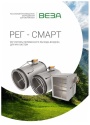
Каталог продукции Веза 2024 - Регуляторы переменного расхода воздуха РЕГ-СМАРТ для VAV-систем. pdf, 1.83 Mb
Каталог регуляторов переменного расхода воздуха РЕГ-СМАРТ для VAV-систем: назначение, конструкция, исполнения, технические характеристики, габаритные размеры, обозначение при заказе. -

Каталог продукции Веза 2025 - Воздушные завесы. pdf, 4.97 Mb
Каталог воздушных завес Веза AeroWall, AeroGuard, AeroBlast: назначение, конструкция и исполнения, технические характеристики, габаритные размеры, подбор.
Новое в инструкциях
-

Модульные чиллеры с воздушным охлаждением конденсатора Electrolux серии EMACO. pdf, 10.13 Mb
Модели: EMACO-220.V2, EMACO-440.V2. Инструкция по эксплуатации чиллера с воздушным охлаждением конденсатора (модульного блока системы кондиционирования): меры безопасности, технические и эксплуатационные требования, принцип работы, технические характеристики, подъём блока, схема соединения нескольких модулей, вспомогательный электронагреватель, электрическая схема, регулировка и пуск, техническое обслуживание, поиск и устранение неисправностей, инструкция к пульту управления, коды аварийных сигналов, схема подключения внешнего насоса. -

Компрессорно-конденсаторные блоки Shuft серии SDVC. pdf, 5.57 Mb
Модели: SDVC-V03WDHN1, V05WDHN1, V08WDHN1, V10WDHN1, V14WDHN1, V16WDHN1. Инструкция по эксплуатации и руководство по монтажу наружного блока: эксплуатация, обслуживание, диагностика и коды неисправностей, монтаж, трубопроводы хладагента, электроподключение, конфигурация, пробный пуск, технические характеристики. -

Полупромышленные кассетные сплит-системы Shuft серии SFLC_C. pdf, 11.33 Mb
Модели: SFLC_C/in-18…60HN1_V2, SFLC_C/out-18…60HN1_V2, панели SFLC-PC_V2, SFLC-PS_V2. Руководство по эксплуатации: устройство, проводной пульт, монтаж, электрические схемы подключения, размеры, технические характеристики, устранение неисправностей, протоколы приёмки и тестового запуска, гарантийный талон.