

Инструкция на Контроллеры Lowara серии SM30 для установок повышения давления
Контроллеры Lowara серии SM30 для установок повышения давления серии GS. Инструкция по монтажу и эксплуатации.
Загружаем документ…
Текст инструкции
-
MANUALE PROGRAMMAZIONE
GRUPPI PRESSIONE VELOCITA’ FISSA Istruzioni d’installazione e uso en FIXED SPEED BOOSTER SETS PROGRAMMING MANUAL Installation and Operating Instructions fr MANUEL DE PROGRAMMATION GROUPES DE SUPRESSION à VITESSE FIXE Directives d’utilisation de pt es PROGRAMMIERHANDBUCH FÜR DRUCKANLAGEN MIT FIXER…
-
AVVERTIMENTI PER LA SICUREZZA DELLE PERSONE E DELLE COSE
Di seguito i simboli utilizzati PERICOLO Rischio di dani alle persone, e alle cose se non osservate quanto prescritto SCOSSE ELETTRICHE Rischio di scosse elettriche se non osservate quanto prescritto ATTENZIONE AVVERTENZA Rischio di danni alle cose o all'ambiente se non osservate quanto prescritto.…
-
1 GENERALITÀ
I gruppi di pressione Lowara serie GSD, GSY sono progettati per trasferire e aumentare la pressione dell'acqua pulita negli impianti idrici di abitazioni, uffici, comunità e industria. Questo manuale descrive la programmazione della scheda elettronica di controllo in seguito denominata SM30 BSETF3…
-
Simbolo
Nome Descrizione ↑UP/SU Commuta tra il modo Automatico e quello Manuale Scorrimento in avanti delle finestre Incremento di un valore durante "modifica dato" ↓DOWN /GIU’ Scorrimento indietro delle finestre Decremento di un valore durante "modifica dato" OK/MENU’ Conferma menù Conferma dato inserito…
-
INFORMAZIONI PER L'INSTALLATORE
4 INSTALLAZIONE La scheda è fornita già collegata nel quadro e programmata, se necessario modificare le impostazioni vedere il capitolo Impostazioni. Per i collegamenti fare riferimento allo schema del quadro elettrico. Non avviare le pompe prima di averle riempite di liquido. Vedere il manuale…
-
.1.1 Gruppo A, B ingressi digitali, digitali, optoisolati N° Sigla COM PR1 PR2 PR3 TERM1 TERM2 TERM3 AUX1 9 AUX2 10 AUX3 Descrizione Terminale comune per ingressi digitali ON/OFF Pressostato comando pompa 1 Pressostato comando pompa 2 Pressostato comando pompa 3 Protezione termica / PTC pompa 1…
-
4.1.5 Gruppo F, controllo livello N° Sigla HIGH LOW COM Descrizione Ingresso sonda alto livello / galleggiante / pressostato di minima Ingresso sonda basso livello Comune circuito sonde / galleggiante / pressostato di minima Caratteristiche: Tensione alimentazione 3.6Vp-p. 4.1.6 4.1.6 Gruppo G…
-
5 IMPOSTAZIONI GENERALI
ATTENZIONE Le regolazioni possono influire sul corretto funzionamento del gruppo. 5.1 Modo Modo automatico / manuale All’ accensione la scheda elettronica si dispone in modo automatico. Nel caso di sistema con sensore di pressione appare la finestra: AUTOMATICO AI1 + ###.## bar ##.## è il valore di…
-
Per modificare un parametro o accedere ad un submenù, all’interno di una finestra, premere tasto
OK/MENU’. Il parametro in modifica appare tra due parentesi quadre [ ] se facente parte di una lista, mentre per i valori numerici un cursore lampeggiante indica la cifra in editazione; in entrambe i casi, usare i pulsanti ↑UP e ↓DOWN per modificare il valore. Se un parametro è un numero a più cifre…
-
6.2 Menù parametri
I parametri di configurazione e di controllo della macchina vengono inseriti da tastiera durante le operazioni di taratura e di collaudo effettuate in fabbrica, ma possono essere modificati in seguito. Poiché il gruppo non può essere utilizzato durante le operazioni d’inserimento dei parametri è…
-
F.SCALA SENSORE
Fondo scala sensore: è definito dal tipo di sensore scelto. Pressione 0-10 bar 0-16 bar 0-25 bar 0-50 bar Livello Ultrasuoni: 0-15 m Piezometrico: 0-10 m Temperatura -200 + 850 °C Portata DN80 3.62-181 mc/h DN100 5.65-283 mc/h DN125 8.84-442 mc/h DN150 12.7-637 mc/h DN200 22.6-1131 mc/h DN250…
-
6.2.2 SOGLIE AVVIO/STOP
AVVIO/STOP DELLE POMPE Nota: I parametri SOGLIE sono impostabili solo con sistema a sensore di pressione o di livello. Le soglie devono essere impostate in considerazione delle prestazioni idrauliche della pompa (cuva Q-H) e del tipo di impianto. Fase Display 0 SOGLIE 1 SOGLIA STOP P1 2 SOGLIA START…
-
6.2.4 TEMPORIZZAZIONI
Le temporizzazioni sono attive sia con sistema a pressotati che con sistema a sensori. Fase Display 0 TEMPORIZZAZIONI 1 RIT. START P1 2 RIT. START P2-P3 3 RIT. STOP P1 4 RIT. STOP P2- P3 5 TEMPI RIDOTTI Commento Campo Default Ritardo sull’avviamento P1 (pilota inclusa). Il conteggio della…
-
GIORNO
3 ORA 4 MINUTI Impostazione del giorno di esecuzione autoprova (parametro attivo solo nel caso la sorgente di comando è impostata OROLOGIO INT.) Impostazione ora di esecuzione autoprova (parametro attivo solo nel caso la sorgente di comando è impostata OROLOGIO INT.) Impostazione minuti di…
-
Quando l’autoprova
l’autoprova risulta fallita fallita Se durante l’autoprova (qualsiasi sia la pompa in funzione) interviene il Bulbo Fuori Curva (B.F.C.), installato a bordo gruppo, l’autoprova viene interrotta definitivamente ed il gruppo ritornerà a funzionare in modo automatico. A display compare la scritta…
-
Fase
Display 0 RELE’ ALLARME 1 RIT. RELE’ ON 2 RIT. RELE’ OFF 3 LOGICA RELE’ 4 DISATTIV. RELE’ 5 RELE’ ON TERMICO 6 RELE’ ON LIVELLO 7 RELE’ ON SENSORE 8 RELE’ ON B.F.C. 9 RELE’ ON ALL. EST. 10 RELE’ ON MAX P. 11 RELE’ ON S.MIN P. Commento Campo Default Ritardo in secondi attivazione del Relè allarme…
-
RIT.SOG. MIN. P
3 SOGLIA MAX P. 4 RIT. MAX PRES. 5 NOME ALL. EXT 6 ALL. TERMICO P1 7 ALL. TERMICO P2 8 ALL. TERMICO P3 9 ALL. BASSO LIV. 10 RIT. BASSO LIV. 11 ALLARME B.F.C. 12 RES.REGISTRO ALL. Funzione disponibile solo con sistema a sensore di pressione e solo se è abilitato il relativo allarme (parametro…
-
Impostare a zero il tempo di ritardo (parametro RIT. IN AUX3 all’interno del MENU’ I/O DIGITALI)
dell’allarme di fuori curva. Con l’impianto in pressione, mediante jumper di by-pass posti sulla scheda (vedi capitolo 4.2), inibire il funzionamento delle pompe. Predisporre il gruppo al funzionamento automatico. Aprire lentamente un prelievo per far scendere la pressione nel collettore di mandata.…
-
FILTRO AI1
4 UNITA’ MISURA AI1 5 TIPO SENS. AI2 6 TARAT. ZERO AI2 7 FILTRO AI2 8 UNITA’ MISURA AI2 9 USCITA ANALOGICA 10 TIPO USCITA AN. Filtro software (nr.campionature) del 1..199 segnale analogico ingresso AI1 Impostazione dell’unità di misura DISABILITATO sull’ingresso AI1 bar °C mc/h m Tipo di trasduttore…
-
CONFIG. IN. AUX3
7 RIT. IN AUX 1 8 RIT. IN. AUX2 9 RIT. IN. AUX3 Configurazione ingresso AUX3 come cambio set (NO) o interruttore di fuori curva B.F.C. Tempo di ritardo in secondi all’attivazione ingresso AUX1. Visibile solo se AUX1 è abilitato Tempo di ritardo in secondi all’attivazione ingresso AUX2. Visibile solo…
-
CONFIG. RELE’3
4 CONFIG. RELE’4 5 CONFIG. RELE’5 6 CONFIG. RELE’6 Permette di configurare il relè OUT_3 della scheda opzionale RILS6 Permette di configurare il relè OUT_4 della scheda opzionale RILS6 Permette di configurare il relè OUT_5 della scheda opzionale RILS6 Permette di configurare il relè OUT_6 della…
-
6.2.18 CONTAORE
Fase Display 0 CONTAORE CONTAORE P1 CONTAORE P2 CONTAORE P3 AZZERA CONTAORE Commento Campo Lettura contaore pompa 1 Lettura contaore pompa 2 Lettura contaore pompa 3 Azzeramento memoria contaore pompe Default INFORMAZIONI PER L'INSTALLATORE E L’UTILIZZATORE 7 ALLARMI Nel modo MANUALE e AUTOMATICO si…
-
S.TENSIONE
ALLARME ESTERNO configurato come Sovratensione/ Sottotensione S.TEMPERATURA ALLARME esterno configurato come Sovratemperatura ALL.ESTERNO ALLARME ESTERNO configurato come Blocco da esterno SOGLIA MIN.PR. ALLARME PRESSIONE MINIMA (tramite sensore). ALLARME B.F.C. ALLARME INTERVENTO BULBO FUORI CURVA…
-
8 STRUTTURA PARAMETRI
9 BUS DI CAMPO 26
-
Elenco dei principali parametri R (Read) e R/W (Read/Write) disponibili Modbus
-
40142 40143 40144 40145 40146 40147 40148 40149 40150 40151 40152 40153 40154 40155 40156 40157 40158 40159 40160 40161 40162 40163 40164 40165 40166 40167 40168 40169 40170 40171 40172 40173 40174 40175 40176 40177 REG.ALLARMI: min. 1° interven. REG.ALLARMI: tipo 2° interven. REG.ALLARMI: data 2°…
-
Prima di intervenire sul gruppo scollegare l'alimentazione elettrica e verificare che non vi siano
componenti idraulici in pressione. Guasto 1. Scheda spenta Causa Rimedio 1. Alimentazione elettrica scollegata Collegare l'alimentazione 2. Fusibile bruciato nel quadro. Verificare la tensione 24 Vac di alimentazione nel quadro elettrico, a valle del trasformatore degli ausiliari. Sostituire il…
-
SAFETY WARNINGS FOR PERSONS AND PROPERTY
The symbols used are shown below DANGER Risk of injury to persons and property if the requirements are not observed. ELECTRIC SHOCK Risk of electric shock if the requirements are not observed. CAUTION WARNING Risk of damage to property or to the environment if the requirements are not observed.…
-
1 GENERAL INFORMATION
Lowara series GSD and GSY booster sets are designed to transfer and increase the pressure of clean water in plumbing systems in homes, offices, communities and industry. This manual describes the programming of the electronic control board, referred to below as SM30 BSETF3. For the instructions for…
-
Symbol
Name Description ↑UP/SU Switch between Automatic and Manual mode Scroll windows up Increase by one value during “edit data” ↓DOWN /GIU’ Scroll windows down Decrease by one value during “edit data” OK/MENU’ Confirm menu Confirm data inserted P1, P2, P3 Manual mode, start (ON) and stop (OFF) pump “n”.…
-
INFORMATION FOR THE INSTALLER
4 INSTALLATION The board is supplied already connected in the panel and programmed; if it is necessary to alter the settings, see the Settings chapter. For the connections, refer to the diagram of the electric panel. Do not start the pumps until they have been filled with liquid. See the pump…
-
4.1.1 Group A, B optoinsulated digital inputs
N° Code Description 1 COM Common terminal for ON/OFF digital inputs 2 PR1 Pump 1 control pressure switch 3 PR2 Pump 2 control pressure switch 4 PR3 Pump 3 control pressure switch 5 TERM1 Thermal protection / PTC pump 1 6 TERM2 Thermal protection / PTC pump 2 7 TERM3 Thermal protection / PTC pump 3 8…
-
4.1.5 Group F, level control
control N° Code Description 22 HIGH High level probe / float / minimum pressure switch input 23 LOW Low level probe input 24 COM Probes / float / minimum pressure switch common circuit Characteristics: Voltage 3.6Vp-p 4.1.6 Group G, analog inputs/outputs inputs/outputs N° Code Description 25 GND_A…
-
5 GENERAL SETTINGS
CAUTION The adjustments may influence correct operation of the set. 5.1 Automatic / manual manual mode When switched on the electronic board is set in automatic mode. In the case of a system with a pressure sensor, this window appears: AUTO AI1 + ###.## bar ##.## is the current pressure value. In…
-
↓DOWN buttons to change the value
If a parameter is a number of several figures, these are changed separately, press OK/MENU to move on to the next figure. Once the desired value has been obtained, press OK/MENU to confirm the value or press P3 (ESC) to cancel. To leave a menu or a submenu, press P3 (ESC) or repeatedly press the ↑UP…
-
6.2 Parameters menu
The machine configuration and control parameters are inserted from the keyboard during the adjustment and testing operations performed in the factory, but they may be changed later. As the set cannot be used during the parameter inserting operations, it is necessary to close the stop valve on the…
-
SENSOR F.S
Sensor full scale: this is defined by the type of sensor chosen. Pressure 0-10 bar 0-16 bar 0-25 bar 0-50 bar Level Ultrasound: 0-15 m Piezometric: 0-10 m Temperature -200 + 850 °C Flow DN80 3.62-181 mc/h DN100 5.65-283 mc/h DN125 8.84-442 mc/h DN150 12.7-637 mc/h DN200 22.6-1131 mc/h DN250…
-
6.2.2 PUMP START/STOP THRESHOLDS
Note: The THRESHOLDS parameters can be set only with a system with a pressure or level sensor. The thresholds must be set considering the hydraulic performances of the pump (curve Q-H) and of the type of system. Phase Display 0 THRESHOLDS 1 P1 STOP THRESH. 2 P1 START THRESH. 3 P2 STOP THRESH. 4 P2…
-
6.2.4 TIMING
Timing is active both with systems with pressure switches and with systems with sensors. Phase Display 0 TIMING 1 P1 START DELAY 2 P2-3 START DELAY 3 P1 STOP DELAY 4 P2-3 STOP DELAY 5 DYNAMIC TIMES Comment Field Default Delay in starting P1 (jockey included). The time count begins from the start…
-
DAY
3 HOUR 4 MINUTES Setting of the day autotest is to be performed (parameter active only if the command source is set as INTERNAL CLOCK) Setting of the hour when autotest is to be performed (parameter active only if the command source is set as INTERNAL CLOCK) Setting of the minutes when autotest is…
-
When the autotest has failed
If during the autotest (whatever pump is operating) the minimum pressure switch (CONV.L.SWITCH) installed on the set trips, the autotest is definitively interrupted and the set resumes working in automatic mode. The display shows the message AUTOTEST FAIL P#. CONV.L.SWITCH intervention is delayed by…
-
Display
0 ALARM RELAY 1 DELAY ON RELAY 2 DELAY OFF RELAY 3 LOGIC RELAY 4 DISABLE RELAY 5 RELAY ON O.L. 6 RELAY ON L.O.W. 7 RELAY ON SENSOR 8 RELAY ON C.LIMIT 9 RELAY ON EXT.AL. 10 RELAY ON MAX P. 11 RELAY ON MIN P. Comment Field Default Delay in seconds of alarm relay activation Delay in seconds of alarm…
-
MIN.PRES.DELAY
3 MAX.PRES.THRES H. 4 MAX.PRES.DELAY 5 EXT.AL. DEFINE 6 P1 OVERLOAD 7 P2 OVERLOAD 8 P3 OVERLOAD 9 LOW WATER ALARM 10 L.O.W. AL.DELAY 11 CONVEYOR LIMIT 12 ALARMS RESET Function available only with systems with a pressure sensor and only if the respective alarm is enabled (previous parameter). Delay…
-
Set the delay time at zero (parameter AUX3 IN DELAY in the DIGITAL IN/OUT MENU) of the minimum
pressure switch alarm. With the system under pressure, inhibit pump operation with the bypass jumpers on the board (see chapter 4.2). Configure the set to work in automatic mode. Slowly open a drawing point to bring down the pressure in the delivery manifold. As the pressure lowers, the pump leds…
-
AI1 FILTER
4 AI1 UNIT Software filter (no. samples) of the analog input AI1 signal Setting the unit of measurement on input AI1 5 AI2 SENSOR TYPE Type of transducer connected to the analog input AI2 (if selected on System) 6 ZERO ADJUST AI2 7 AI2 FILTER 8 AI2 UNIT Visible only if 4-20mA selected. Acquisition…
-
CONFIG. AUX3 IN
7 AUX1 IN DELAY 8 AUX2 IN DELAY 9 AUX3 IN DELAY Configuration of input AUX3 as change set (NO) or minimum pressure switch CONV.L.SWITCH Delay time in seconds till activation of input AUX1. Visible only if AUX1 is enabled. Delay time in seconds till activation of input AUX2. Visible only if AUX2 is…
-
REL.OUT4 CONFIG
5 REL.OUT5 CONFIG 6 REL.OUT6 CONFIG Allows you to configure the OUT_4 relay of the RILS6 optional board Allows you to configure the OUT_5 relay of the RILS6 optional board Allows you to configure the OUT_6 relay of the RILS6 optional board See configuration 1 See configuration 1 See configuration 1…
-
6.2.18 HOUR COUNTER
Phase Display HOUR COUNTER P1 OPERAT.HOURS P2 OPERAT.HOURS P3 OPERAT.HOURS OP.HOURS RESET Comment Field Reads pump 1 operating hours Reads pump 2 operating hours Reads pump 3 operating hours Resets memory of pump hour counter Default INFORMATION FOR THE INSTALLER AND USER 7 ALARMS In MANUAL and…
-
HIGH PRESSURE
OVERVOLTAGE OVERTEMPERATURE EXT.TRIP DEVICE MIN.PRES.THRESH. CONVEYOR LIMIT LOW WATER ALARM OVERLOAD P# PTC P# FAILURE AUTOTEST FAIL P# SENSOR# ALARM HIGH PRESSURE ALARM High pressure for tripping of high pressure switch with external pressure connected to AUX1. Blocks pump operation as long as…
-
8 PARAMETER STRUCTURE
-
9 FIELD BUS
-
40140 40141 40142 40143 40144 40145 40146 40147 40148 40149 40150 40151 40152 40153 40154 40155 40156 40157 40158 40159 40160 40161 40162 40163 40164 40165 40166 40167 40168 40169 40170 40171 40172 40173 40174 40175 40176 40177 ALARMS LOG: date 1st trip ALARMS LOG: hour 1st trip ALARMS LOG: min. 1st…
-
12 TROUBLESHOOTING
Maintenance and repair operations must be carried out by qualified personnel. Before doing any work on the set, disconnect the electric power supply and ensure that there are no hydraulic components under pressure. Fault 1. Board off Cause Remedy 1. Electric power supply disconnected Connect power…
-
1 GÉNÉRALITÉS
Les groupes de surpression Lowara série GSD, GSY ont été conçus pour pomper de l’eau claire et augmenter sa pression dans les installations hydrauliques des habitations, bureaux, collectivités et industries. Ce manuel décrit la programmation de la carte électronique de contrôle, dénommée SM30 BSETF3…
-
Symbole
Nom ↑Flèche HAUT Description Commutation entre mode Automatique et mode Manuel Passage à la fenêtre suivante Augmentation des valeurs en « édition données » ↓Flèche BAS Passage à la fenêtre précédente Diminution des valeurs en « édition données » OK/MENU Validation choix menu Validation donnée…
-
INFORMATIONS POUR L'INSTALLATEUR
4 INSTALLATION La carte est fournie déjà câblée dans le coffret et programmée ; s’il faut modifier la programmation, voir le chapitre Programmation. Pour les connexions, se référer au schéma du coffret électrique. Ne pas mettre en marche les pompes avant de les avoir remplies de liquide. Voir le…
-
entrées numériques, optocouplées N° Sigle COM PR1 PR2 PR3 TERM1 TERM2 TERM3 AUX1 9 AUX2 10 AUX3 Description Contact commun pour entrées numériques Marche/Arrêt Pressostat commande pompe 1 Pressostat commande pompe 2 Pressostat commande pompe 3 Protection thermique / PTC pompe 1 Protection thermique…
-
4.1.5 Groupe F, contrôle
contrôle niveau N° Sigle HIGH LOW COM Description Entrée sonde niveau maximum / flotteur / pressostat pression minimum Entrée sonde niveau minimum Commun circuit sondes / flotteur / pressostat pression minimum Caractéristiques : Tension 3.6V p-p 4.1.6 Groupe G, Entrées/sorties analogiques N° Sigle…
-
5 PROGRAMMATION GÉNÉRALE
ATTENTION Les réglages peuvent influencer le fonctionnement correct du groupe. 5.1 Mode automatique automatique / manuel Au démarrage, la carte électronique s’active en mode automatique. Dans le cas de système avec capteur de pression, l’afficheur visualise : AUTOMATIQUE AI1 + ###.## bar ##.## est…
-
Pour modifier un paramètre ou accéder à un sous-menu, appuyer sur la touche OK/MENU depuis
l’intérieur d’une fenêtre. Quand il fait partie d’une liste, le paramètre en édition apparaît entre deux crochets [ ], tandis que, pour les valeurs numériques, un curseur clignotant indique le chiffre en édition. Dans les deux cas, utiliser les touches ↑Flèche HAUT et ↓Flèche BAS pour modifier la…
-
6.2 Menu paramètres
paramètres Les paramètres de configuration et de contrôle de la machine sont saisis depuis le clavier pendant les opérations d’étalonnage et d’essai effectuées à l’usine ; il est cependant possible de les modifier par la suite. Le groupe ne peut pas être utilisé pendant les opérations de saisie des…
-
ÉCHELLE CAPTEUR Pleine échelle du capteur : il est défini par le type de capteur choisi. Pression 0-10 bars 0-16 bars 0-25 bars 0-50 bars Niveau Ultrasons : 0-15 m Piézométrique : 0-10 m Température -200 + 850 °C Débit DN80 3.62-181 m3/h DN100 5.65-283 m3/h DN125 8.84-442 m3/h DN150 12.7-637 m3/h…
-
6.2.2 SEUILS MARCHE/ARRÊT DES POMPES
Nota : Les paramètres LIMITES ne sont programmables que dans les systèmes avec capteur de pression ou de niveau. Les seuils doivent être programmés en considérant les performances hydrauliques de la pompe (courbe Q-H) et du type d’installation. Phase Afficheur 0 LIMITES 1 SEUIL ARRÊT P1 2 SEUIL…
-
6.2.4 TEMPORISATION
Les temporisations sont actives aussi bien avec le système à pressostats qu’avec le système à capteurs. Phase Afficheur Observations Champ Défaut 0 TEMPORISATIONS 1 RET. DÉM. P1 Retard au démarrage de P1 (p. jockey 0..100 s 3s comprise). Le comptage de la temporisation débute avec la demande de…
-
JOUR
3 HEURE 4 MINUTES Programmation du jour d’exécution de l’autotest (paramètre actif uniquement si la source de commande programmée est HORLOGE INT.) Programmation de l’heure d’exécution de l’autotest (paramètre actif uniquement si la source de commande programmée est HORLOGE INT.) Programmation des…
-
Quand l’autotest donne un résultat négatif
Si le Manocontacteur Basse Pression (Hors Courbe) embarqué intervient pendant l’autotest (indépendamment de la pompe examinée), l’autotest est interrompu et le groupe reprend le fonctionnement en mode automatique. L’afficheur visualise le message A-TEST ÉCHOUÉ P#. L’intervention du manocontacteur…
-
Afficheur
0 RELAIS ALARME 1 RET. RELAIS ON 2 RET. RELAIS OFF 3 LOGIQUE RELAIS 4 DÉSACT. RELAIS 5 RELAIS THERM. ON 6 RELAIS NIV. ON 7 RELAIS CAPT. ON 8 REL. H.COURBE ON 9 REL. ALAR EXT ON 10 RELAIS MAX P ON 11 RELAIS MIN P ON 70 Observations Champ Défaut Retard d’activation du Relais alarme, en secondes Retard…
-
6.2.8 PROGRAMMATION ALARMES
Phase Afficheur 0 ALARMES 1 SEUIL PRESS. MIN. Observations ALARME PRESSION MINIMUM Fonction disponible uniquement avec système à capteur de pression. Programmer la valeur de pression minimum au-dessus de laquelle le système arrête le fonctionnement des pompes. Le contrôle du système est exécuté…
-
ALARM. NIV. BAS 10 RET. NIV. BAS 11 ALARM. H.COURBE 12 RESET REG. ALARM. ALARME NIVEAU MINIMUM Intervention protection logicielle de niveau minimum/faible pression en aspiration. Depuis circuit sondes HAUT, BAS, COM aux contacts 22 – 23- 24 Temps de retard en secondes d’arrêt pompes pour…
-
FILTRE AI2 Filtre logiciel (n° échantillonnages) du signal analogique entrée AI2. Programmation de l’unité de mesure sur l’entrée AI2. 8 UNITÉ AI2 9 SORTIE ANALOG. Fonction associable à la sortie analogique Out_A. 10 TYP. SORT. ANALO Pleine échelle sortie analogique AO1 1..199 1 DÉSACTIVÉ bar °C…
-
6.2.12 PROGRAMMATION CONTRÔLE À DISTANCE RS485
Phase Afficheur 0 CONTRÔLE DISTANT 1 RS485 ACTIVÉ 2 3 MODBUS ADRESSE PARITÉ 4 5 RETARD RÉPONSE BAUD RATE Observations Champ Activation OUI NON 1:31 Sans Pair Impair 0..199 ms 1200 2400 4800 9600 19200 38400 57600 115200 Défaut OUI 1 Sans 0 38400 6.2.13 CONFIGURATION RELAIS CARTE RILS6 RETRANSMISSION…
-
6.2.14 PARAMÈTRES PAR DÉFAUT
Phase Afficheur 0 DÉFAUT 1 PARAMÈTRE DÉFAUT Observations Champ Restauration de tous les paramètres par défaut (paramètres d’usine). OUI NON Défaut 6.2.15 PROGRAMMATION HORLOGE Phase Afficheur 0 HORLOGE 1 PARAM. DATE Observations Champ Programmation de la date 2 Programmation de l’heure et des…
-
7 ALARMES En mode MANUEL et AUTOMATIQUE, on peut afficher le Registre Alarmes en appuyant en même temps sur les touches ↑Flèche HAUT et OK/MENU. Toutes les alarmes sont signalées et mémorisées ; cependant, seules quelques-unes bloquent le fonctionnement automatique du groupe. Toutes les alarmes…
-
SURTENSION
ALARME EXTERNE configurée comme Surtension/Soustension SURTEMP. ALARME externe configurée comme Surtempérature ALARME EXTERNE ALARME EXTERNE configurée comme Blocage depuis signal externe SEUIL PRESS. MIN ALARME PRESSION MINIMUM (depuis capteur). ALARM. H.COURBE ALARME INTERVENTION MANOCONTACTEUR…
-
9 BUS DE TERRAIN
-
40141 40142 40143 40144 40145 40146 40147 40148 40149 40150 40151 40152 40153 40154 40155 40156 40157 40158 40159 40160 40161 40162 40163 40164 40165 40166 40167 40168 40169 40170 40171 40172 40173 40174 REG. ALARMES : heure 1ère interv. REG. ALARMES : minutes 1ère interv. REG. ALARMES : type 2ème…
-
40176 40177 REG. ALARMES : date 10ème interv. REG. ALARMES : heure 10ème interv. REG. ALARMES : minutes 10ème interv. R R R 10 MAINTENANCE DE LA CARTE ÉLECTRONIQUE La carte n’a pas besoin d’entretien. 11 RÉPARATIONSRÉPARATIONS- PIÈCES DE RECHANGE ATTENTION Pour les réparations, s’adresser à du…
-
HINWEISE FÜR DIE SICHERHEIT VON PERSONEN UND SACHEN
Nachstehend sind die verwendeten Symbole dargestellt: GEFAHR! Bei Nichtbeachten der Vorschriften besteht die Gefahr von Personen- und Sachschäden. STROMSCHLÄGE Bei Nichtbeachten der Vorschriften besteht die Gefahr von Stromschlägen. ACHTUNG! HINWEIS Bei Nichtbeachten der Vorschriften besteht die…
-
1 ALLGEMEINES
Die Druckanlagen Lowara der Baureihe GSD, GSY sind zur Druckerzeugung und -erhöhung in sauberem Wasser in Hydraulikanlagen in Wohnungen, Büros, Gemeinschaftsanlage und in der Industrie ausgelegt. Im vorliegenden Handbuch wird die Programmierung der elektronischen Steuerkarte (nachfolgend SM30 BSETF3…
-
Symbol
Bezeichnung Beschreibung ↑UP/ NACH OBEN Umschalten zwischen Automatik und Handbetrieb Weiterblättern in den Masken Erhöhen eines Wertes bei „Angabe ändern“ ↓DOWN /NACH UNTEN Zurückblättern in den Masken Vermindern eines Wertes bei „Angabe ändern“ OK/MENÜ Menü bestätigen Eingabe bestätigen P1, P2, P3…
-
INFORMATIONEN FÜR DEN INSTALLATEUR
4 INSTALLATION Die Karte wird bereits programmiert und an die Schalttafel angeschlossen geliefert. Zur Veränderung der Einstellungen, siehe Kapitel Einstellungen. Für die Anschlüsse ist auf den Schaltplan der Schalttafel Bezug zu nehmen. Die Pumpen erst anlassen, nachdem sie mit Flüssigkeit gefüllt…
-
4.1.1 Gruppe A, B, optoisolierte digitale Eingänge
Nr. Zeichen COM PR1 PR2 PR3 TERM1 TERM2 TERM3 AUX1 9 AUX2 10 AUX3 Beschreibung Gemeinsames Terminal für Digitaleingänge ON/OFF Druckwächter zur Steuerung der Pumpe 1 Druckwächter zur Steuerung der Pumpe 2 Druckwächter zur Steuerung der Pumpe 3 Wärmeschutzschalter / PTC Pumpe 1 Wärmeschutzschalter /…
-
4.15 Gruppe F, Pegelkontrolle
Nr. Zeichen HIGH LOW COM Beschreibung Eingang Sonde hoher Pegel / Schwimmerschalter / Mindestdruckwächter Eingang Mindestpegelsonde Gemeinsamer Eingang Sondenkreis / Schwimmerschalter / Mindestdruckwächter Merkmale: Spannung 0-11 V, Genauigkeit 0,3% Stromeingang 0-22 mA, Genauigkeit 0,3%…
-
5 ALLGEMEINE EINSTELLUNGEN
ACHTUNG! Die Einstellungen können sich auf den korrekten Betrieb der Einheit auswirken. 5.1 Automatik / Handbetrieb Beim Einschalten ist die Elektronikkarte für den automatischen Betrieb ausgelegt. Bei Systemen mit Druckfühlern erscheint folgende Maske: AUTOMATIK AI1 + ###.## bar ##.## ist der…
-
Der zu ändernde Parameter erscheint zwischen zwei rechteckigen Klammern [ ], wenn er zu einer
Aufstellung gehört. Bei numerischen Werten zeigt ein blinkender Kursor die einzugebende Zahl an. In beiden Fällen verwendet man die Tasten ↑UP und ↓DOWN, um den Wert zu ändern. Wenn es sich bei dem Parameter um eine Zahl mit mehreren Ziffern handelt, müssen diese separat geändert werden. Um die…
-
dem Drucksammelrohr bzw. alle Abnehmer geschlossen werden
Bei Einschalten der Schalttafel ist das System standardmäßig für den automatischen Betrieb vorbereitet. Um von AUTOMATIK auf HANDBETRIEB und umgekehrt umzuschalten, drückt man die Taste ↑UP. Auf dem Display erscheint bei druckfühlergesteuerten Systemen: AUTOMATIK AI1 + ###.## bar ##.## ist der…
-
PEGELKONTROLLE
6 SENSIB. SONDE 7 FEEDBACK Pegel Ultraschall: 0-15 m Piezometrisch: 0-10 m Temperatur -200 + 850 °C Fördermenge: DN80 3.62-181 m3/h DN100 5.65-283 m3/h DN125 8.84-442 m3/h DN150 12,7-637 m3/h DN200 22.6-1131 m3/h DN250 35.3-1727 m3/h Diese Vorrichtung wird zur Kontrolle des niedrigen…
-
Display
0 SCHWELLEN 1 STOPPSCHW. P1 2 STARTSCHW. P1 3 STOPPSCHW. P2 4 STARTSCHW. P2 5 STOPPSCHW. P3 6 STARTSCHW. P3 Kommentar Anwendungen mit Druck / Pegelfühlern Stoppschwelle (OFF) (Druck/Pegel) für Pumpe 1 Startschwelle (ON) (Druck/Pegel) für Pumpe 1 Stoppschwelle (OFF) (Druck/Pegel) für Pumpe 2…
-
0 ZEITGEBUNGEN VERZ. START P1 2 VERZ. START P2-P3 3 VERZ. STOP P1 4 VERZ. STOP P2-P3 5 REDUZ. ZEITEN Anlassverzögerung P1 (einschl. Pilotpumpe). Die Zeitzählung beginnt mit der Startanforderung von Seiten des Druckwächters/Fühlers. Anlassverzögerung P2 - P3. Die Zeitzählung beginnt mit der…
-
UHRZEIT
4 MINUTEN Vorgabe der Uhrzeit für den Selbsttest (dieser Parameter ist nur aktiv, wenn die Befehlherkunft auf INT. UHR eingestellt ist). Vorgabe der Minuten für den Selbsttest (dieser Parameter ist nur aktiv, wenn die Befehlherkunft auf INT. UHR eingestellt ist). 0..24 h 10 0..60 min 00 Selbsttest…
-
Wenn während des Selbsttests (ganz gleich mit welcher Pumpe ) die auf der Einheit installierte
Überlastsicherung eingreift, wird der Autotest definitiv abgebrochen und die Pumpe kehrt zur automatischen Betriebsweise zurück. Auf dem Display erscheint die Schrift SELBSTT. NEG. P# Der Eingriff der Überlastsicherung erfolgt verzögert um die mittels dem Parameter VERZ. IN AUX3 vorgegebenen Zeit.…
-
Modalitäten und Arten von Alarmen aktiviert. Das Alarmrelais ist nur dann verfügbar und
programmierbar, wenn die Funktion SELBSTTEST nicht befähigt ist. Bei befähigtem SELBSTTEST werden die nachfolgend beschriebenen Parameter nicht angezeigt. Phase Display 0 ALARMRELAIS 1 VERZ. RELAIS ON 2 VERZ. RELAIS OFF 3 RELAISLOGIK 4 RELAIS ENTAKT. 5 RELAIS ON WÄRMES. 6 RELAIS ON PEGEL 7 RELAIS ON…
-
Display
0 ALARME 1 SCHW. MIN.DR. Kommentar ALARM MINDESTDRUCK Diese Funktion ist nur für Systeme mit Druckfühlern verfügbar. Den Mindestdruckwert vorgeben, unter welchem das System den Pumpenbetrieb anhält. Die Kontrolle des Systems erfolgt nur, wenn mindestens eine Pumpe eingeschaltet ist. Durch Eingabe…
-
AL. WÄRMES. P1
7 AL. WÄRMES. P2 8 AL. WÄRMES. P3 9 AL. NIED. PEGEL 10 VERZ. NIED. PEGEL 11 ALARM ÜBERL. 12 RES.ALARMREG. ALARM WÄRMESCHALTER P1 Eingriff Überlastschutz / PTC Pumpe 1 ALARM WÄRMESCHALTER P2 Eingriff Überlastschutz / PTC Pumpe 2 ALARM WÄRMESCHALTER P3 Eingriff Überlastschutz / PTC Pumpe 3 ALARM…
-
6.2.9 TAG/NACHTTAG/NACHT-BETRIEB
Phase Display 0 TAG/NACHT 1 FUNKTION T/N 2 WERT T/N 3 BEGINN STD N/T 4 BEGINN MIN. T/N 5 ENDE STD N/T 6 ENDE MIN T/N Kommentar Nur für Systeme mit Fühler Damit werden die Schwellen für den N-Betrieb (Nacht) geändert. Diese Schwelle kann mittels der internen Uhr, einer an AUX3 angeschlossene…
-
FÜHLERTYP AI2
6 NULL- EINST. Al2 7 8 Art des mit dem Analogeingang Al2 verbundenen Umformers (sofern im System vorgewählt) Wird nur angezeigt, wenn 4-20mA ausgewählt ist. Nullübernahme auf Eingang 4-20mA Die Eichung kann nur im Bereich 3,5÷ 4.5mA vorgenommen werden. Bei positivem Ergebnis erscheint die Meldung…
-
VERZ. IN. AUX2 9 VERZ. IN. AUX3 Verzögerungszeit in Sekunden der Aktivierung des Eingangs AUX2. Wird nur angezeigt, wenn AUX2 befähigt ist. Verzögerungszeit in Sekunden der Aktivierung des Eingangs AUX3. Wird nur angezeigt, wenn AUX3 befähigt ist. 0..20 s 0s 0..20 s 0s 6.2.12 PROGRAMMIERUNG DER…
-
KONFIG. RELAIS 5
6 KONFIG. RELAIS 6 Damit kann das Relais OUT_5 der Karte RILS6 (Option) konfiguriert werden. Damit kann das Relais OUT_6 der Karte RILS6 (Option) konfiguriert werden. Siehe Konfiguration 1 PEGEL Siehe Konfiguration 1 POWER ON 6.2.14 DEFAULTDEFAULT-PARAMETER PARAMETER Phase Display 0 DEFAULT 1…
-
6.2.18 STUNDENZÄHLER
Phase Display 0 STUNDENZÄHLER 1 STUNDENZÄHLER P1 2 STUNDENZÄHLER P2 3 STUNDENZÄHLER P3 4 ZÄHLER RESET Kommentar Feld Ablesen des Betriebsstundenzählers der Pumpe 1 Ablesen des Betriebsstundenzählers der Pumpe 2 Ablesen des Betriebsstundenzählers der Pumpe 3 Rückstellen des Speichers der…
-
LISTE DER ALARME
ALARMREGISTER Definition SCHW. MAX.DR ALARM MAXIMALER DRUCK (mittels Fühler) AL. ÜBERDRUCK ALARM ÜBERDRUCK durch einen externen Druckwächter ÜBERSPANN. EXTERNER ALARM, konfiguriert als Über-/ und Unterspannung ÜBERTEMP. Externer ALARM, konfiguriert als Übertemperatur EXT.ALARM EXTERNER ALARM…
-
AL. NIED. PEGEL
ALARM NIEDRIGER PEGEL (mittels Sonde/Schwimmerschalt er) AL. WÄRMES. P# ALARM EINGRIFF ALARM PTC P# WÄRMESCHALTER / PTC PUMPE N.# SELBSTT. NEG. P# ALARM FÜHLER 106 ALARM SELBSTTEST FEHLGESCHLAGEN ALARM FÜHLER # Der Sondenkontrollkreis HIGH sendet das Signal 'Fehlen von Wasser'. LOW, COM an den…
-
8 STRUKTUR DER PARAMETER
-
9 FELDBUS
-
ALARMREG.: Typ 1. Eingriff 40139 40140 40141 40142 40143 40144 40145 40146 40147 40148 40149 40150 40151 40152 40153 40154 40155 40156 40157 40158 40159 40160 40161 40162 40163 40164 40165 40166 40167 40168 40169 40170 40171 40172 40173 40174 40175 40176 40177 ALARMREG.: Datum 1. Eingriff ALARMREG.…
-
10 WARTUNG DER ELEKTRONIKKARTE
Die Karte ist wartungsfrei. 11 REPARATUREN UND ERSATZTEILE ACHTUNG! Wenden Sie sich zwecks Reparaturen an qualifiziertes Personal und verwenden Sie ausschließlich Originalersatzteile. 12 SCHADENSSUCHE Reparaturen und Wartungseingriffe müssen von qualifiziertem Personal ausgeführt werden. Vor…
-
ADVERTÊNCIAS PARA A SEGURANÇA DAS PESSOAS E DAS COISAS
A seguir é referido o significado dos símbolos utilizados PERIGO A não observância da prescrição comporta um risco de danos às pessoas e às coisas CHOQUES ELÉCTRICOS A não observância da prescrição comporta um risco de choques eléctricos ATENÇÃO ADVERTÊNCIA A não observância da prescrição comporta…
-
1 CARACTERÍSTICAS
CARACTERÍSTICAS GERAIS As unidades de pressurização Lowara série GSD, GSY são projectadas para transferir e aumentar a pressão da água limpa nas instalações hídricas de habitações, escritórios, comunidades e indústrias. Este manual descreve a programação da placa electrónica de controlo, a seguir…
-
Símbolo
Nome Descrição ↑UP/PARA CIMA Comuta entre o modo Automático e o Manual Rolamento para a frente das janelas Aumento de um valor durante “modificar dado” ↓DOWN / PARA BAIXO Rolamento para trás das janelas Diminuição de um valor durante “modificar dado” OK/MENU Confirmar menu Confirmar dado inserido…
-
INFORMAÇÕES PARA O INSTALADOR
4 INSTALAÇÃO A placa é fornecida já ligada ao quadro e programada, se resultar necessário modificar as programações, consulte o capítulo Programações. Para as ligações, ter como referência o esquema do quadro eléctrico. Não pôr em funcionamento as bombas antes de as ter enchido de líquido. Consultar…
-
4.1.1 Grupo A, B entradas digitais, optoisoladas
N.° Sigla COM PR1 PR2 PR3 TERM1 TERM2 TERM3 AUX1 9 AUX2 10 AUX3 Descrição Terminal comum para entradas digitais ON/OFF Pressostato comando bomba 1 Pressostato comando bomba 2 Pressostato comando bomba 3 Protecção térmica / PTC bomba 1 Protecção térmica / PTC bomba 2 Protecção térmica / PTC bomba 3…
-
4.1.5 Grupo F, controlo do nível
N.° Sigla HIGH LOW COM Descrição Entrada sonda nível alto / flutuador / pressostato de mínima Entrada sonda nível baixo Comum circuito sondas / flutuador / pressostato de mínima Características: Tensão 0-11 V, precisão 0,3%; Entrada corrente 0-22 mA, precisão 0,3%, protecção contra o curto-circuito.…
-
5 DEFINIÇÕES
DEFINIÇÕES GERAIS ATENÇÃO As regulações podem influenciar o funcionamento correcto da unidade. 5.1 Modo automático / manual Ao ligar, a placa electrónica coloca-se no modo automático. No caso de sistema com sensor de pressão, aparece a janela: AUTOMÁTICO AI1 + ###.## bar ##.## é o valor de pressão…
-
Para modificar um parâmetro ou ter acesso a um submenu, no interior de uma janela, pressionar a tecla OK/MENU. O parâmetro a modificar aparece entre dois parênteses quadrados [ ] se faz parte de uma lista, enquanto para os valores numéricos um cursor intermitente indica o algarismo interessado; em…
-
6.2 Menu parâmetros
Os parâmetros de configuração e de controlo da máquina são inseridos do teclado durante as operações de ajuste e de ensaio realizadas na fábrica, mas podem ser modificados a seguir. Uma vez que a unidade não pode ser utilizada durante as operações de introdução dos parâmetros, é necessário fechar a…
-
CONTR. NÍVEL
6 SENSIB. SONDAS 7 RETROACÇÃO 0-25 bar 0-50 bar Nível Ultra-sons: 0-15 m Piezométrico: 0-10 m Temperatura -200°C + 850 °C Débito DN80 3.62-181 mc/h DN100 5.65-283 mc/h DN125 8.84-442 mc/h DN150 12.7-637 mc/h DN200 22.6-1131 mc/h DN250 35.3-1727 mc/h Dispositivo utilizado para o controlo de baixo…
-
6.2.2 LIMIARES ARRANQUE/PARAGEM DAS BOMBAS
Advertência: Os parâmetros LIMIARES são programáveis só com sistema de sensor de pressão ou de nível. Os limiares devem ser programados considerando os rendimentos hidráulicos da bomba (curva Q-H) e o tipo de instalação. Fase Visor 0 LIMIARES 1 LIMIAR STOP P1 2 LIMIAR START P1 3 LIMIAR STOP P2 4…
-
6.2.4 TEMPORIZAÇÕES
As temporizações estão activas quer com sistema de pressostatos quer com sistema de sensores. Fase Visor 0 TEMPORIZAÇÕES 1 ATR. START P1 2 ATR. START P2-P3 3 ATR. STOP P1 4 ATR. STOP P2-P3 5 TEMPOS REDUZIDOS Comentário Campo Default Atraso no arranque da P1 (piloto incluída). A contagem da…
-
DIA
3 HORAS 4 MINUTOS Programação do dia de execução do auto-teste (parâmetro activo só se a fonte de comando for programada em RELÓGIO INT.) Programação das horas de execução do auto-teste (parâmetro activo só se a fonte de comando for programada em RELÓGIO INT.) Programação dos minutos de execução do…
-
Quando o autoauto-teste falhar
Se durante o auto-teste (qualquer que seja a bomba a funcionar) se activar o Alarme de pressão mínima (Fora da Curva), instalado na unidade, o auto-teste é interrompido definitivamente e a unidade começa a funcionar de novo no modo automático. No visor aparece a indicação AUTO-T. FALHADO P#. A…
-
6.2.7 PROGRAMAÇÃO DO RELÉ DE ALARME
A placa SM30 BSETF3 tem à disposição um relé de alarme de saída que se activa no modo e para o tipo de alarmes descritos a seguir. O relé de alarme está disponível, e programável, só e exclusivamente se a função AUTOAUTO-TESTE não tem sido habilitada. Se o AUTOAUTO-TESTE está habilitado, habilitado…
-
6.2.8 PROGRAMAÇÃO DOS ALARMES
Fase Visor 0 ALARMES 1 LIMIAR PR. MÍN. 2 ATR.LIM. MÍN. P. 3 LIMIAR P. MÁX. 4 ATR. PRESSÃO MÁX. 5 NOME AL. EXT. 6 AL. TÉRMICO P1 7 AL. TÉRMICO P2 8 AL. TÉRMICO P3 9 AL. NÍVEL BAIXO 126 Comentário Campo Default ALARME PRES. MÍN. Função disponível só com sistema com sensor de pressão. Programar o valor…
-
11 12 ATR. NÍVEL BAIXO Tempo de atraso em segundos do bloqueio das bombas por activação da protecção de baixo nível/pressão em aspiração. ALARME ALARME PRESSÃO MÍNIMA (F.C.) PRESSÃO MÍN. Activação da protecção contra o (F.C.) funcionamento fora da curva da/s bomba/s. Sinal proveniente do interruptor…
-
6.2.10 PROGRAMAÇÃO DE ENTRADAS / SAÍDAS ANALÓGICAS
-
6.2.11 PROGRAMAÇÃO DE ENTRADAS / SAÍDAS DIGITAIS
Fase Visor 0 IN/OUT DIGITAIS 1 LÓGICA PR1 2 LÓGICA PR2 3 LÓGICA PR3 4 CONFIG. ENT. AUX1 5 CONFIG. ENT. AUX2 6 CONFIG. ENT. AUX3 7 ATR. ENT. AUX 1 8 ATR. ENT. AUX2 9 ATR. ENT. AUX3 Comentário Campo Grampo 2 só se habilitado o funcionamento com pressostatos. Grampo 3 só se habilitado o funcionamento…
-
6.2.13 CONFIGURAÇÃO RELÉ PLACA RILS6 RETRANSMISSÃO
RETRANSMISSÃO SINAIS CONTACTOS LIMPOS Fase 1 Visor 0 CONFIG. RILS6 CONFIG. RELÉ 1 2 CONFIG RELÉ 2 3 CONFIG. RELÉ 3 4 CONFIG. RELÉ 4 5 CONFIG. RELÉ 5 6 CONFIG. RELÉ 6 Comentário Campo Default Permite configurar o relé OUT_1 da placa opcional RILS6 AUT - MAN P1 P2 P3 TÉRMICO NÍVEL P MÁX P MÍN AL. EXT.…
-
BARRA GRÁFICA
Habilita a visualização da barra indicadora na Entrada seleccionada como retroacção. Disponível só com sistemas com sensor SIM NÃO NÃO Comentário Campo Default 6.2.17 SOFTWARE Fase 1 Visor 0 SOFTWARE VERSÃO Só leitura nome programa carregado e n.º release BSETF3 REL .01 6.2.18 CONTADOR HORÁRIO Fase…
-
MENU DE REGISTO DOS ALARMES
Fase Visor Mensagem de Alarme 1: Data e hora Mensagem de Alarme 2: Data e hora Mensagem de Alarme 3: Data e hora Mensagem de Alarme 4: Data e hora Comentário Alarme mais recente Alarme Alarme Alarme mais antigo LISTA DOS ALARMES REGISTO DOS ALARMES LIMIAR PR. MÁX. Definição Comentário ALARME PRESSÃO…
-
ALARME PRESSÃO
MÍNIMA (F.C). ALARME ACTIVAÇÃO INTERRUPTOR PRESSÃO MÍNIMA (FORA DA CURVA) AL. NÍVEL BAIXO ALARME NÍVEL BAIXO (através de sondas/flutuador) ALARME TÉRMICO P# ALARME PTC P# ALARME ACTIVAÇÃO TÉRMICO / PTC BOMBA n.# ALARME DE AUTO-TESTE FALHADO ALARME SENSOR # AUTO-T. FALHADO P# ALARME SENSOR Activação…
-
8 ESTRUTURA DOS PARÂMETROS
PARÂMETROS 9 BUS DE CAMPO 134
-
Lista dos parâmetros principais R (Read) e R/W (Read/Write) disponíveis Modbus
-
40142 40143 40144 40145 40146 40147 40148 40149 40150 40151 40152 40153 40154 40155 40156 40157 40158 40159 40160 40161 40162 40163 40164 40165 40166 40167 40168 40169 40170 40171 40172 40173 40174 40175 40176 40177 REG.ALARMES: min. 1° activação REG.ALARMES: tipo 2° activ. REG.ALARMES: data 2°…
-
As operações de manutenção e as reparações só podem ser realizadas por pessoal qualificado
Antes de quaisquer intervenções na unidade, desligar a alimentação eléctrica e verificar que não haja componentes hidráulicos sob pressão. Avaria 1. Placa desligada Causa Remédio 1. Alimentação eléctrica desligada. Ligar a alimentação 2. Fusível queimado no quadro Verificar a tensão 24 Vac de…
-
ADVERTENCIAS PARA LA SEGURIDAD DE LAS PERSONAS Y LAS COSAS
A continuación se indican los símbolos utilizados: PELIGRO Riesgo de daños a las personas y las cosas, si no se observan las prescripciones. ELECTROCUCIÓN Riesgo de electrocución, si no se observan las prescripciones. ATENCIÓN ADVERTENCIA Riesgo de daños a las cosas o al medio ambiente, si no se…
-
1 GENERALIDADES
Los grupos de presión Lowara de las series GSD y GSY están diseñados para transferir y aumentar la presión del agua limpia en las instalaciones hidráulicas de viviendas, oficinas, comunidades e industrias. En este manual se describe la programación de la tarjeta electrónica de control que en…
-
Símbolo
Nombre Descripción ↑UP/ARRIBA Conmuta entre el modo Automático y Manual Desplazamiento adelante de las ventanas Incremento de un valor durante "modificación dato" ↓DOWN /ABAJO Desplazamiento atrás de las ventanas Decremento de un valor durante "modificación dato" OK/MENÚ Confirmación menú…
-
INFORMACIÓN PARA EL INSTALADOR
4 INSTALACIÓN La tarjeta se suministra ya conectada al cuadro y programada; si es necesario modificar la configuración, véase el capítulo Configuraciones. Para las conexiones hacer referencia al esquema del cuadro eléctrico. No poner en marcha las bombas antes de haberlas llenado con el líquido.…
-
4.1.1 Grupo A, B entradas digitales, optoaisladas
N.° Sigla COM PR1 PR2 PR3 TERM1 TERM2 TERM3 AUX1 9 AUX2 10 AUX3 Descripción Terminal común para entradas digitales ON/OFF Presóstato mando bomba 1 Presóstato mando bomba 2 Presóstato mando bomba 3 Protección térmica / PTC bomba 1 Protección térmica / PTC bomba 2 Protección térmica / PTC bomba 3…
-
4.1.5 Grupo F, control nivel
N.° Sigla HIGH LOW COM Descripción Entrada sonda alto nivel / interruptor de nivel / presóstato de mínima Entrada sonda bajo nivel Común circuito sondas / interruptor de nivel / presóstato de mínima Características: Tensión 3.6V p-p 4.1.6 Grupo G, Entradas/salidas analógicas N.° Sigla GND_A Out_A…
-
5 CONFIGURACIONES GENERALES
ATENCIÓN Las regulaciones pueden influir en el correcto funcionamiento del grupo. 5.1 Modo automático / manual En el momento del encendido, la tarjeta electrónica se pone en modo automático. En caso de sistema con sensor de presión aparece la ventana: AUTOMÁTICO AI1 + ###.## bar ##.## es el valor de…
-
Si el parámetro es un número de varias cifras, éstas se modifican separadamente; para pasar a la cifra siguiente pulsar OK/MENÚ. Una vez obtenido el valor deseado, pulsar OK/MENÚ para confirmar el valor o pulsar la tecla P3 (ESC) para anular. Para salir de un menú o un submenú pulsar la tecla P3…
-
6.2 Menú parámetros
Los parámetros de configuración y control de la máquina se introducen mediante el teclado durante las operaciones de calibrado y prueba realizadas en fábrica, pero se pueden modificar posteriormente. Como el grupo no se puede utilizar durante las operaciones de introducción de los parámetros, es…
-
F. ESCALA SENSOR
5 CONTR. NIVEL 6 SENSIB. SONDAS 7 RETROACCIÓN Fondo escala sensor: se define según el tipo de sensor elegido. Presión 0-10 bares 0-16 bares 0-25 bares 0-50 bares Nivel Ultrasonidos: 0-15 m Piezométrico: 0-10 m Temperatura -200 + 850 °C Caudal DN80 3,62-181 m³/h DN100 5,65-283 m³/h DN125 8,84-442…
-
6.2.2 UMBRALES START/STOP DE LAS BOMBAS
Nota: los parámetros UMBRALES se pueden configurar solamente mediante sistema con sensor de presión o nivel. Los umbrales se deben configurar teniendo en cuenta las prestaciones hidráulicas de la bomba (curva QH) y el tipo de instalación. Fase Pantalla 0 UMBRALES 1 UMBRAL STOP P1 2 UMBRAL START P1 3…
-
6.2.4 TEMPORIZACIONES
Las temporizaciones están activadas tanto con el sistema de presóstatos como con el sistema de sensores. Fase Pantalla 0 TEMPORIZACIONES 1 RET. START P1 2 RET. START P2-P3 3 RET. STOP P1 4 RET. STOP P2-P3 5 TIEMPOS REDUCIDOS Comentario Campo Default Retardo en la puesta en marcha P1 (bomba piloto…
-
DÍA
3 HORA 4 MINUTOS Programación del día de ejecución de la autoprueba (parámetro activo sólo si la fuente del mando está configurada en RELOJ INT.). Programación de la hora de ejecución de la autoprueba (parámetro activo sólo si la fuente del mando está configurada en RELOJ INT.). Programación de los…
-
Cuándo la autoprueba se considera fracasada
Si durante la autoprueba (cualquiera que sea la bomba en funcionamiento) se activa el Bulbo Fuera de Curva (B.F.C.), instalado en el grupo, la autoprueba se interrumpe definitivamente y el grupo vuelve a funcionar de modo automático. En la pantalla aparece el mensaje AUTOP. FRACASADA P#. La…
-
6.2.7 PROGRAMACIÓN DEL RELÉ DE ALARMA
La tarjeta SM30 BSETF3 dispone de un relé de alarma de salida que se activa en el modo y para el tipo de alarmas que se describen a continuación. El relé de alarma está disponible, y se puede programar, programar, única y exclusivamente si la función AUTOPRUEBA no está habilitada. Si la AUTOPRUEBA…
-
6.2.8 PROGRAMACIÓN DE ALARMAS
Fase Pantalla 0 ALARMAS 1 UMBRAL PR. MÍN. Comentario ALARMA PRES. MÍN. Función disponible solamente en el sistema con sensor de presión. Configurar el valor de presión mínima debajo del cual el sistema interrumpe el funcionamiento de las bombas. El control del sistema se realiza solamente si está…
-
AL. BAJO NIV. ALARMA BAJO NIVEL Activación de la protección hardware de bajo nivel/presión en aspiración Del circuito sondas HIGH, LOW y COM a los bornes 22 – 23 – 24 RET. BAJO NIV. Tiempo de retardo en segundos bloqueo bombas por activación protección bajo nivel/presión en aspiración. ALARMA B.F.C.…
-
6.2.9 FUNCIÓN NOCHE/DÍA
-
TIPO SENS. AI2
-
CONFIG. IN. AUX3
7 RET. IN AUX 1 8 RET. IN. AUX2 9 RET. IN. AUX3 Configuración entrada AUX3 como cambio de set (NO) o interruptor de fuera curva B.F.C. Tiempo de retardo en segundos en la activación de la entrada AUX1. Visible sólo si AUX1 está habilitado. Tiempo de retardo en segundos en la activación de la entrada…
-
CONFIG. RELÉ 2
3 CONFIG. RELÉ3 4 CONFIG. RELÉ4 5 CONFIG. RELÉ5 6 CONFIG. RELÉ6 Permite configurar el relé OUT_2 de la tarjeta opcional RILS6. Permite configurar el relé OUT_3 de la tarjeta opcional RILS6. Permite configurar el relé OUT_4 de la tarjeta opcional RILS6. Permite configurar el relé OUT_5 de la tarjeta…
-
6.2.18 CUENTAHORAS
Fase Pantalla 0 CUENTAHORAS CUENTAHORAS P1 CUENTAHORAS P2 CUENTAHORAS P3 RESETEA CUENTAHORAS Comentario Campo Lectura cuentahoras bomba 1 Lectura cuentahoras bomba 2 Lectura cuentahoras bomba 3 Reset memoria cuentahoras bombas Default INFORMACIÓN PARA EL INSTALADOR Y EL USUARIO 7 ALARMAS En el modo…
-
LISTA DE ALARMAS
REGISTRO DE ALARMAS UMBRAL PR. MÁX. Definición Comentario ALARMA PRESIÓN MÁXIMA (mediante sensor) AL. ALTA PRES. ALARMA ALTA PRESIÓN mediante presóstato exterior S.TENSIÓN ALARMA EXTERIOR configurada como Sobretensión/Subte nsión S.TEMPERATURA ALARMA exterior configurada como Sobretemperatura AL.…
-
AL. BAJO NIV
ALARMA BAJO NIVEL (mediante sondas/interruptor de nivel) Señal de falta de agua desde el circuito de control sondas HIGH, LOW y COM a los bornes 22 – 23 – 24 produce la parada de todas las bombas activas. Está deshabilitada en el modo de funcionamiento manual. ALARMA RELÉ TÉRMICO P# ALARMA PTC P#…
-
8 ESTRUCTURA
ESTRUCTURA DE LOS PARÁMETROS 162
-
9 BUS DE CAMPO
-
REG. DE ALARMAS: hora 7ª activación R 40165 REG. DE ALARMAS: min. 7ª activación REG. DE ALARMAS: tipo 8ª activación REG. DE ALARMAS: fecha 8ª activación REG. DE ALARMAS: hora 8ª activación REG. DE ALARMAS: min. 8ª activación REG. DE ALARMAS: tipo 9ª activación REG. DE ALARMAS: fecha 9ª activación…
-
12 POSIBLES AVERÍAS
Las operaciones de mantenimiento y reparación deben ser realizadas por personal calificado. Antes de intervenir en el grupo, desconectar la alimentación eléctrica y verificar que no haya componentes hidráulicos bajo presión. Avería Causa Remedio 1. 1. Alimentación eléctrica desconectada Conectar la…
-
nl
da no sv fi is et lv lt pl cs sk hu ro bg sl hr sr el tr ru uk ar Lowara si riserva il diritto di apportare modifiche senza obbligo di preavviso. Lowara reserves the right to make modifications without prior notice. Lowara se réserve le droit d’apporter des modifications sans obligation de préavis.…
Схемы, таблицы и рисунки — в просмотре документа выше. Клик по номеру страницы открывает её в просмотре.
Новое в каталогах
-

Каталог продукции Веза 2026 - Оборудование для противодымной вентиляции. pdf, 7.85 Mb
Каталог оборудования Веза для противодымной вентиляции: вентиляторы дымоудаления и подпора, противопожарные клапаны, люки и прочее оборудование — назначение, технические характеристики, габаритные размеры. -
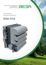
Каталог продукции Веза - Воздухоприемное устройство РОН 510. pdf, 1.96 Mb
Каталог воздухоприёмных устройств РОН 510: назначение, конструкция, технические характеристики, габаритные размеры, обозначение при заказе. -
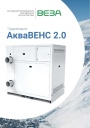
Каталог продукции Веза 2026 - Гидромодули АкваВЕНС 2.0. pdf, 1.29 Mb
Каталог гидромодулей АкваВЕНС 2.0: назначение, конструкция и исполнения, гидравлические схемы, технические характеристики, габаритные размеры, обозначение при заказе.
Новое в инструкциях
-
Крышные вентиляторы Shuft серии RMV VIM. pdf, 4.41 Mb
Модели: RMVE 190/300-2 … 450/670-4, RMVD 311/440-4 … 630/950-4 VIM. Паспорт (объединённый эксплуатационный документ): описание, массогабаритные показатели, монтаж, схемы электрических соединений, пуск, обслуживание, гарантийные обязательства, технические данные. -
Вентиляторы в круглом корпусе Shuft серии SH. pdf, 646.47 Kb
Модели: SH 160, 200, 250, 315, 400. Руководство по установке, эксплуатации и техническому обслуживанию: технические характеристики, размеры, монтаж, электрические подключения, ввод в эксплуатацию, обслуживание и чистка, устранение неисправностей. -
Приточно-вытяжные установки Shuft серии NOVA. pdf, 4.29 Mb
Модель NOVA-300. Инструкция по монтажу и обслуживанию: принципиальная схема установки, массогабаритные показатели, монтаж воздуховодов и дренажа, подключение электропитания, схема электрических соединений, пусконаладка, обслуживание, неисправности, подключение к системе диспетчеризации.