

Инструкция на Мультизональные VRF системы ARUN60GS2, ARUN50GS2, ARUN40GS2
Инструкция по монтажу
Загружаем документ…
Текст инструкции
-
website http://www.lgservice.com
Outdoor Unit R410A MODELS: ARUN Series ARUV Series (1Ø, 220~240V, 50Hz / 1Ø, 220V, 60Hz) ESPAÑOL INSTALLATION MANUAL ITALIANO System ENGLISH LG FRANÇAIS DEUTSCH • Please read this installation manual completely before installing the product. • Installation work must be performed in accordance with…
-
This symbol indicates the possibility of death or serious injury
This symbol indicates the possibility of injury or damage to properties only. ■ Meanings of symbols used in this manual are as shown below. Be sure not to do. Be sure to follow the instruction. ■ Installation Have all electric work done by a licensed electrician according to "Electric Facility…
-
When installing and moving the air conditioner
to another site, do not charge it with a different refrigerant from the refrigerant specified on the unit. Do not reconstruct to change the settings of the protection devices. • If a different refrigerant or air is mixed with the original refrigerant, the refrigerant cycle may malfunction and the…
-
Do not install the product where the noise or
hot air from the outdoor unit could damage the neighborhoods. • Low refrigerant levels may cause failure of product. • It may cause a problem for your neighbors. Keep level even when installing the product. Do not install the unit where combustible gas may leak. • To avoid vibration or water…
-
Install and insulate the drain hose to ensure that water is drained away properly based on the
installation manual. • A bad connection may cause water leakage. Be very careful about product transportation. • Only one person should not carry the product if it weighs more than 20 kg. • Some products use PP bands for packaging. Do not use any PP bands for a means of transportation. It is…
-
Installation Process
Indicate clearly who is to be responsible for switch settings Preparation of contract drawings Make relationship between outdoor, indoor, remote controller, and option connections clear. (Prepare control circuit diagram) Sleeve and insert work Take account of gradient of drain piping Outdoor unit…
-
Outdoor Units Information
Outdoor Units Information CAUTION Ratio of the connectable Indoor Units to the Outdoor: Within 50 ~ 130% Ratio of running Indoor Units to the Outdoor: Within 10 ~ 100% A combination operation over 100% cause to reduce each indoor unit capacity. Power Supply: Outdoor Unit (1Ø, 220~240V, 50Hz/1Ø…
-
Before Installation
Before Installation Environment-friendly Alternative Refrigerant R410A CAUTION: • The wall thickness of the piping should comply with the relevant local and national regulations for the designed pressure 3.8MPa • Since R410A is a mixed refrigerant, the required additional refrigerant must be charged…
-
Select the Best Location
Select the Best Location 1. Select space for installing outdoor unit, which will meet the following conditions: • No direct thermal radiation from other heat sources • No possibility of annoying neighbors by noise from unit • No exposition to strong wind • With strength which bears weight of unit •…
-
■ In case of obstacles on the discharge side
-
2. Collective installation
-
Collective / Continuous Installation for roof top use
Space required for collective installation and continuous installation: When installing several units, leave space between each block as shown below considering passage for air and people. 1. One row of stand alone installation r 0o 200 ore m r 0o 100more or 100 ore m or 200 ore m [Unit:mm] 2. Rows…
-
Anti-vibration
materials Concrete base Spring washer Frame Nut Four bolt are required 3 thread ridges H-Beam [Unit:mm] Foundation bolt executing method If it is necessary to prevent the unit from falling over, install as shown in the figure. • Prepare all 4 wires as indicated in the drawing • Unscrew the top plate…
-
Preparation of Piping
Main cause of gas leakage is defect in flaring work. Carry out correct flaring work in the following procedure. 1) Cut the pipes and the cable. ■ Use the accessory piping kit or the pipes purchased locally. ■ Measure the distance between the indoor and the outdoor unit. ■ Cut the pipes a little…
-
FLARE SHAPE and FLARE NUT TIGHTENING TORQUE
Pipe size Tightening Torque(kgf·cm) A(mm) flare shape 9.52 340~420 12.6~13.0 90° ±2 12.7 550~660 15.8~16.2 15.88 630~820 19.0~19.4 45 A ° ±2 R=0.4~0.8 CAUTION Always use a charge hose for service port connection. After tightening the cap, check that no refrigerant leaks are present. When loosening a…
-
■ Connecting the pipes to the outdoor unit
1. Liquid pipe • Align the center of the pipings and sufficiently tighten the flare nut with fingers. • Finally, tighten the flare nut with torque wrench until the wrench clicks. - When tightening the flare nut with torque wrench, ensure the direction for tightening follows the arrow on the wrench.…
-
Cautions for Handling Service Valve
• The service valves are closed at shipment from the factory ENGLISH CAUTION Make sure to keep the valve open during operation The names of parts of the service valve are shown in the figure. 1 1. Service point 2. Shut-off Valve 3. Filed piping connection 2 4. Valve cover 3 4 • since the side boards…
-
1. Use the following materials for refrigerant piping
• Material: Seamless phosphorous deoxidized copper pipe • Wall thickness : Comply with the relevant local and national regulations for the designed pressure 3.8MPa. We recommend the following table as the minimum wall thickness. Outer diameter [mm] 6.35 9.52 12.7 15.88 19.05 22.2 25.4 28.58 31.8…
-
ENGLISH Refrigerant piping Pipe to be brazed Nitrogen Taping Valve Pressure-reducing valve WARNING When installing and moving the air conditioner to another site, be sure to make recharge refrigerant after perfect evacuation. - If a different refrigerant or air is mixed with the original…
-
Selection of Refrigerant Piping
Outdoor unit Gas pipe Liquid pipe Branching pipe Main pipe Indoor unit Branching pipe No. Piping parts Name Selection of pipe size Size of main pipe Outdoor unit Outdoor unit capacity type Main pipe 1st branching section 4 HP 5 HP 6 HP Liquid pipe [mm(inch)] Ø9.52(3/8) Ø9.52(3/8) Ø9.52(3/8) Gas pipe…
-
Allowable Length/Height Difference of Refrigerant Piping
-
■ Header Method
Example : 6 Indoor Units connected : Outdoor Unit : 1st branch : Indoor Units : Sealed piping H 50m L 150m 40m ➲ Total pipe length = A+a+b+c+d+e+f ≤ 300m L l H h Longest pipe length * Equivalent pipe length A+f ≤ 150m A+f ≤ 175m Longest pipe length after 1st branch f ≤ 40m Difference in…
-
■ Combination of Y branch/header method
Example : 5 Indoor Units connected H 50m ENGLISH : Outdoor Unit : 1st branch (Y branch) : Y branch : Indoor Unit : Header : Sealed piping L 150m 40m Branch pipe can not be used after header ➲ Refrigerant pipe diameter from branch to branch (B,C) Downward Indoor Unit total capacity [kW(Btu/h)]…
-
The Amount of Refrigerant
-
If a negative result is obtained from the calculation, no refrigerant needs to be added
Regulation for refrigerant leakage : the amount of refrigerant leakage should satisfy the following equation for human safety. Total amount of refrigerant in the system Volume of the room at which Indoor Unit of the least capacity is installed 0.44 ( kg / m3 ) If the above equation can not be…
-
Distribution Method
1. Line Distribution 2nd 1st 3rd main pipe distribution 1st 1st 2nd 2nd 3rd 3rd 1st Main pipe Distribution 2nd Main pipe Distribution 2. Vertical Distribution Ensure that the branch pipes are attached vertically. 3. The others Header 28 Outdoor Unit
-
Branch Pipe Fitting
Y branch A To Outdoor Unit B To Branch Piping or Indoor Unit • Ensure that the branch pipes are attached horizontally or vertically (see the diagram below.) Horizontal plane Facing downwards Facing upwards Within ± 3° Within ± 3° Within +/- 10° A Viewed from point A in direction of arrow A A To…
-
• When the number of indoor units to be connected to the branch pipes is less than the number of branch pipes available for connection then cap pipes should be fitted to the surplus branches. B Pinched pipe • Fit branch pipe lie in a horizontal plane. Horizontal plane View from point B in the…
-
Selection of Y Branch and Header
-
2. Header
-
Thermal Insulation of Refrigerant Piping
B A C Heat insulation material Adhesive + Heat - resistant polyethylene foam + Adhesive tape Outer covering Indoor Vinyl tape Floor exposed Water-proof hemp cloth + Bronze asphalt Water-proof hemp cloth + Zinc plate + Oily paint Outdoor A Heat insulation material Note: When using polyethylene cover…
-
Leak Test and Vacuum Drying
1. Leak test Gas pipe Nitrogen gas cylinder Liquide pipe Leak test should be made by pressurizing nitrogen gas to 3.8 MPa(38.7kgf/cm2). If the pressure does not drop for 24 hours, the system passes the test. If the pressure drops, check where the nitrogen leaks. For the test method, refer to the…
-
2. Vacuum
• Vacuum drying: Use a vacuum pump that can evacuate to -100.7kPa (5 Torr, -755mmHg). 1) Evacuate the system from the liquid and gas pipes with a vacuum pump for over 2 hrs and bring the system to -100.7kPa. After maintaining system under that condition for over 1 hr, confirm the vacuum gauge rises.…
-
3. Refrigerant charging
Follow following procedure to charge the refrigerant. 1. Open all service valves 2. Run the unit with cooling mode 3. Charging the refrigerant to gas service valve during operation. Charging during cooling operation Gas pipe Refrigerant cylinder Open Liquide pipe Open CAUTION Never charge the…
-
1. Caution
1) Follow ordinance of your governmental organization for technical standard related to electrical equipment, wiring regulations and guidance of each electric power company. WARNING Be sure to have authorized electrical engineers do the electric work using special circuits in accordance with…
-
Outdoor Unit
Outdoor Unit Indoor Unit Indoor Unit Indoor Unit Remote control Indoor Unit Remote control Remote control Remote control Outdoor Unit Outdoor Unit Indoor Unit Indoor Unit Indoor Unit Remote control 2-Core Shield Cable Remote control Indoor Unit Remote control Remote control Multi-Core Cable CAUTION…
-
2. Transmission and Power Lines
1) Transmission cable ENGLISH • Types : shielding wire CVVS or CPEVS • Diameter : over 1.25mm2 • Insulation material : PVC • Maximum allowable temperature: 60°C • Maximum allowable line length: 300m 2) Remote control cable • Types : 3-core cable 3) Simple central control cable • Types : 4-core cable…
-
Wiring of Main Power Supply and Equipment Capacity
Outdoor unit (1Ø, 220~240V, 50Hz / 1Ø, 220V, 60Hz), Indoor unit (1Ø, 220V, 50Hz/60Hz) 1. Separate power supply lines for the indoor units from outdoor unit. 2. Bear in mind ambient conditions (ambient temperature,direct sunlight, rain water,etc.) when proceeding with the wiring and connections. 3.…
-
◆ Precautions when laying power wiring
Use round pressure terminals for connections to the power terminal block. Power wire ENGLISH Round pressure terminal When none are available, follow the instructions below. • Do not connect wiring of different thicknesses to the power terminal block. (Slack in the power wiring may cause abnormal…
-
Example Connection of Transmission Cable
1. 50Hz ■ 1 Outdoor Unit - 1Ø, 220~240V Single Phase 3 wire(L,N,GND) Transmission line (3 line): Wired remote control Single Phase of power supply line(L, N) Power supply switch (Switch fuse : ELCB) Single Phase 3 wire ( L, N ,GND) Power supply 50Hz 220~240V Transmission line (2 shield line)…
-
2. 60Hz
■ 1 Outdoor Unit - 1Ø, 220V Transmission line (3 line): Wired remote control Single Phase of power supply line(L, N) Power supply switch (Switch fuse : ELCB) Single Phase 3 wire ( L, N ,GND) Power supply 60Hz 220V Transmission line (2 shield line): Between Indoor Unit and Outdoor Unit (Main Switch)…
-
DIP Switch Setting
■ Location of setting Switch Main PCB SW01B (DIP S/W) SW02B (DIP S/W) 7 - Segment SW02V Auto addressing SW01V Data confirm ■ Checking according to dip switch setting 1. You can check the setting values of the outdoor unit from the 7 segment LED. The dip switch setting should be changed when the…
-
■ Setting the DIP switch (SW03M)
1. Settings of outdoor unit Function SW01B Setting SW02B Setting ON Remarks ON Power reset is necessary Factory Setting Standard ON Short Pipe Length ON ON ON Long Pipe Length ON Power reset is necessary -Cooling Target Pressure : Standard+39 -Heating Target Pressure : Standard-131 Power reset is…
-
Function
SW01B Setting SW02B Setting ON Remarks ON Snow ON Used when snow piles up On the ODU Fan. Fan operates periodically. ON Accelerates defrost operation Forced Defrosting ON ON Night Silent Operation ON ON Pump Down ON ON Pump Out 1 1 Power reset is necessary Fan RPM down on night time ON Power reset…
-
Automatic Addressing
SW01B (DIP S/W) SW02B (DIP S/W) 7 - Segment SW02V Auto addressing SW01V Data confirm CAUTION In replacement of the indoor unit PCB, always perform auto address setting again. - If power supply is not applied to the indoor unit, operation error occurs. - Auto addressing is only possible on the main…
-
◆ The Procedure of Automatic Addressing
Power On Waiting 3 minutes Press SW02V for 5 sec. Auto addressing start 7-segment LED = 88 Waiting about 2~7 minutes 7-segment LED = 88 NO • Auto addressing setting end Numbers of indoor unit connection set whose addressing is completed are indicated for 30seconds on 7-segment LED after completing…
-
Group Number Setting
-
Cool/Heat Selector Installation and Connection(Heat pump only)
■ Using Cool/Heat Selector Installation and Connection • Connect wires as below figure at the hole of backside of Outdoor Unit Dry Contact. • Insert the wire in the connection hole pushing the "Push" button. • Maximum transmission line length for dry contact : 200m. Mode Change Fan Outdoor Unit…
-
Check to see whether there is any refrigerant leakage, and slack of power or transmission cable. 2 Confirm that 500 V megger shows 2 MΩ or more between power supply terminal block and ground. Do not operate in the case of 2 MΩ or less. NOTE: Never carry out megaohm check over terminal control board.…
-
How to cope with Test Run Abnormality
The phenomena from master component failure Component Phenomenon Not operating Outdoor EEV Check method and Trouble shooting Motor insulation broken Check resistance between terminals and chassis Strainer clogged Change strainer Oil leakage Check oil amount after opening oil port Stop during running…
-
Sensor Checking Function
Note 1) Sensor checking function judges whether the current temperature of indoor and outdoor unit sensors is right or not. It checks 3 indoor temperature sensors, 9 outdoor temperature sensors, 2 outdoor pressure sensors. Start Main PCB SW01S Wait for 3 min. after power reset Main PCB Set the dip…
-
Sensor Check Error Code Display
In case error occurs during sensor checking process, error display is as shown below. Following contents are displayed one after the other on the main PCB of outdoor unit. Indoor sensor error : 319 Outdoor sensor error : 309 Displaying error content Displaying error content ■ Indoor unit error…
-
Refrigerant Checking Function
This function charges appropriate amount of refrigerant automatically through cycle operation. This function judges refrigerant leakage and overcharging. Main PCB SW01S Wait for 3 min. after power reset Main PCB SW01B SW02B Set the Dip S/W. Refrigerant Checking : 1,2,7,14 ON Main PCB SW01V Press the…
-
1. Guaranteed Temperature range(Error occurs out of guaranteed temperature range)
IDU : 20~32°C (buffer ±1°C) ODU : 10~38°C (buffer ±1°C) 2. Set IDU wired remote controller temperature sensor setting as 'IDU'. 3. Make certain that IDU doesn't run with thermo off mode during operation. [ Error contents about auto refrigerant charging function ] 1. : Temperature Range Error (In…
-
Night Silent Operation
In cooling mode, this function makes the ODU fan operate at low RPM to reduce the fan noise of ODU at night which has low cooling load. ENGLISH Max. RPM setting method DIP switch No.12+14 ON ODU SW01B Main PCB power reset ODU SW01S Setting the Fan Max. RPM SW01V SW02V Note 1) Setting complete…
-
Self-Diagnosis Function
Error Indicator • This function indicates types of failure in self-diagnosis and occurrence of failure for air condition. • Error mark is displayed on display window of indoor units and wired remote controller, and 7-segment LED of outdoor unit control board as shown in the table. • If more than two…
-
Title
Cause of Error Outdoor Unit Inverter Compressor System is turned off by outdoor unit Inverter High Discharge Temperature Compressor High Discharge Temperature High Pressure of Outdoor Unit System is turned off by excessive increase of high pressure of outdoor unit Low Pressure of Outdoor Unit System…
-
Caution For Refrigerant Leak
Caution for Refrigerant Leak The installer and system specialist shall secure safety against leakage according to local regulations or standards. The following standards may be applicable if local regulations are not available. Introduction Though the R410A refrigerant is harmless and incombustible…
-
Caution For Refrigerant Leak
(3) With partition and without opening which serve as passage of air to adjoining room Outdoor unit ENGLISH Indoor unit Smallest room ■ Calculate refrigerant concentration Total amount of replenished refrigerant in refrigerant facility (kg) Capacity of smallest room where indoor unit is installed…
-
Installation Guide at the Seaside
Installation Guide at the Seaside CAUTION 1. Air conditioners should not be installed in areas where corrosive gases, such as acid or alkaline gas, are produced. 2. Do not install the product where it could be exposed to sea wind (salty wind) directly. It can result corrosion on the product.…
-
The below Installation guide is limited applicable only for model
ARUN60GS2 This equipment complies with IEC 61000-3-12 provided that the short-circuit power Ssc is greater than or equal to 1032 kVA at the interface point between the user's supply and the public system. It is the responsibility of the installer or user of the equipment to ensure, by consultation…
-
Memo
64 Outdoor Unit
-
Printed in Korea After reading this manual, keep it in a place easily accessible to the user for future reference.
Схемы, таблицы и рисунки — в просмотре документа выше. Клик по номеру страницы открывает её в просмотре.
Новое в каталогах
-
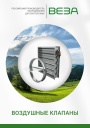
Каталог продукции Веза 2025 - Воздушные клапаны. pdf, 6.71 Mb
Каталог воздушных клапанов Веза: номенклатура, клапаны отсечные и регулирующие РЕГУЛЯР, РЕГУЛЯР-Л, РЕГЛАН, КЕДР и другие — конструкция, исполнения, приводы, технические характеристики, габаритные размеры. -

Каталог продукции Веза 2026 - Оборудование в морском исполнении. pdf, 7.62 Mb
Каталог вентиляционного и холодильного оборудования Веза в морском исполнении: радиальные и осевые вентиляторы, кондиционеры КОМПАС-БОВ, компрессорно-конденсаторные агрегаты КОМПАС-ККБ, шкафы управления КОМПАС-ШСАУ — технические характеристики и размеры. -
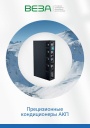
Каталог продукции Веза 2026 - Прецизионные кондиционеры АКП. pdf, 4.90 Mb
Каталог прецизионных кондиционеров АКП: назначение, исполнения, конструкция, технические характеристики, габаритные размеры, обозначение при заказе.
Новое в инструкциях
-
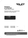
Инверторные сплит-системы Shuft серии Asgard DC. pdf, 8.78 Mb
Модели: SFTHAI/IN-07HN8/BL, 09HN8/BL, 12HN8/BL, SFTHAI/OUT-07HN8/BL, 09HN8/BL, 12HN8/BL. Руководство по эксплуатации: монтажная схема и монтаж, описание пульта управления и режимов работы, Wi-Fi и мобильное приложение, уход и обслуживание, технические характеристики, устранение неисправностей, протоколы приёмки и тестового запуска, гарантийный талон. -
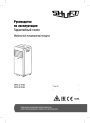
Мобильные кондиционеры Shuft серии Frigo. pdf, 11.28 Mb
Модели: SFPAC-07 KF/N6, SFPAC-09 KF/N6. Руководство по эксплуатации: устройство и технические характеристики, управление кондиционером, монтаж, устранение неисправностей, самодиагностика, транспортировка и хранение, гарантийный талон. -
Прямоугольные канальные вентиляторы Shuft серии RF-B EC. pdf, 7.50 Mb
Модели: RFE-B EC 300x150 … 600x350, RFD-B EC 600x300 … 1000x500. Паспорт (объединённый эксплуатационный документ): описание, массогабаритные показатели, монтаж, подключение электропитания, схема электрического соединения, пуск, обслуживание, неисправности, гарантийные обязательства, технические данные.