

Инструкции на Вентиляционные установки Komfovent серии KOMBI
Руководство по монтажу установок KOMBI: требования безопасности, типы, компоненты, транспортировка, монтаж, электрические подключения и схемы. Документ на английском языке.
Загружаем документ…
Текст инструкции
-
KOMBI
INSTALLATION MANUAL komfovent
-
1. INTRODUCTION
This Installation Manual is intended for professionals, qualified to install the KOMBI hybrid heating and ventilation unit. Qualified professionals are people with sufficient professional experience and knowledge of heating and ventilation systems and installation thereof, knowledge of electrical…
-
KOMBI units are available in various modifications which are indicated as follows
KOMBI 1 - A7 - 2 W - 3 E4,5 - 4 R - 5 C9 6 / CP 7 1. Name of the unit’s range. 2. Nominal heating capacity: A9 – 9 kW; A7 – 7 kW. 3. Hot water tank type: W – standard tank; 4. Integrated electrical water heater capacity: E6 – 6 kW; E4.5 – 4,5 kW; 5. Inspection side: R – right; L – left. 6. Type of…
-
1.2.1. Heat pump
Heat pump takes thermal energy form the outside air and transfers it to water circulating in the heating system or domestic hot water production system. Heat pump assembly consists of a piping system containing refrigerant, compressor, heat exchangers, fan and separate control electronics. KOMBI A7…
-
1.2.3. Hot water preparation system
Hot water preparation system consists of a domestic hot water tank and water distribution pipeline. Hot water section also includes water distribution devices (valves, actuators, pumps) that ensure proper circulation of heating / cooling water and domestic hot water. Fig. 5. Hot water system section…
-
2. TRANSPORTATION AND STORAGE
KOMBI package consists of 2 parts: a heat pump section and a hot water section together with AHU. KOMBI unit must be transported and stored in its original packaging. During transportation, packages must be properly secured and additionally protected against possible mechanical damage, rain or snow.…
-
Fig. 7. Examples of section transportation If it is necessary to reduce the weight of a section (for example, to bring it down to the basement), you can remove the AHU from the hot water section. For this purpose, you must remove the side panel of the hot water section, unscrew water pipes and…
-
3. MECHANICAL INSTALLATION
KOMBI A7 EHA ODA ETA EHA SUP ODA KOMBI A9 EHA ODA ETA EHA SUP ODA Fig. 9. KOMBI principal diagram 1 – fans, 2 – air filters, 3 – heat pump heat exchanger, 4 – water air heater, 5 – rotary heat exchanger, 6 – compressor, 7 – expansion vessel for the heating system (12 l), 8 – domestic hot water tank…
-
3.1. Requirements for Mounting Location and Installation Base
KOMBI units are intended for installation in domestic or technical premises with proper ventilation, at 0–40 °C temperature, 20–80% relative humidity (non-condensing). Air handling units are designed for ambient temperatures from -30 °C to +40 °C. Unit must be mounted on a relatively large and…
-
3.2. List of received parts
• • • • • • • Prior to installation, check whether you received the complete kit of parts. If any part from the list is missing, contact the seller. Heat pump section - 1 pc. Hot water section – 1 pc. Air handling unit – 1 pc. Blind for the heat pump air duct, 400x400 mm – 1 pc. Filters for the air…
-
Tighten two external fasteners at the top
M6x20 x2 Connect wire connectors that are marked with stickers (see section “Installation of Electrical Components”). Make sure that connected wires are marked the same on both sides. Tighten connection pipes to the water tank pipeline. KOMFOVENT UAB reserves the right to change information without…
-
4. MECHANICAL INSTALLATION: AIR DUCTS
Air duct system must be properly designed to ensure low air flow rates and small pressure differences. This will ensure more accurate volumes of ventilated air, lower energy consumption, lower noise level and longer lifetime of the unit. External grilles must be installed as far apart as possible…
-
4.1. Installation of ventilation air duct system
Air is supplied to the AHU through ø 200 mm air ducts. Ducts are fastened to the AHU connection points with self-tapping screws. EHA EHA ODA ODA ETA ETA SUP SUP Fig. 11. AHU air duct connections A sticker on the unit shows the positions of different air flow connections. • • Air intake and exhaust…
-
Ø x 400 500..650 800 x 800 Fig. 13. Structure of a connection box1 1 – external grille, 2 – noise absorbing partitions, 3 – connection for the AHU air duct, 4 – connection for the heat pump air duct Outside, the openings of air ducts and connection boxes are covered with grilles or decorative hoods…
-
≥3m ≥3m Fig. 14. Examples of the KOMBI unit installation together with connection boxes 1 – connection boxes, 2 – air closing dampers, 3 – ducts for ventilation unit, 4 – heat pump ducts, 5 – flexible connections, 6 – noise attenuators for the ventilation system Which exact components should be used…
-
5. MECHANICAL INSTALLATION: HYDRAULIC SYSTEM
Hydraulic system must be designed to meet the needs of the building and the user. Make sure to use materials and components that are compatible with water used in the system, pressure and temperature thereof as well as with other materials used in the unit. Piping of the KOMBI unit is made of…
-
Fig. 16. Underfloor heating 1 – underfloor piping, 2 – expansion vessel1, 3 – shut-off valves, 4 – magnetic filter, 5 – buffer tank, 6 – overflow valve, 7 – manifolds Fig. 17. Heating system with radiators 1 – radiators, 2 – expansion vessel2, 3 – shut-off valves, 4 – magnetic filter, 5 – buffer…
-
Fig. 18. Heating system with fan coils 1 – fan coils, 2 – expansion vessel1, 3 – shut-off valves, 4 – magnetic filter, 5 – buffer tank, 6 – overflow valve, 7 – manifolds Fig. 19. Heating system with a hydraulic separation vessel 1 – piping / radiators / fan coils, 2 – expansion vessel2, 3 – shut-off…
-
5.2. Examples of a hot water system
Below are typical diagrams of the domestic hot water system. An 8 l expansion vessel for the hot water system is integrated inside the KOMBI unit, suitable for a standard water inlet pressure of ~ 4 bar. If the inlet pressure is higher, it is recommended to install an additional expansion vessel…
-
5.3. Connecting pipeline to the unit
Pipes for the heating and hot water system are routed under the unit and connected at the bottom of the water tank section. Pipes of the unit are marked with stickers and arrows indicating the water flow direction: Fig. 22. Water pipeline connections 1 – water supplied to the heating system (1“), 2…
-
5.3.1. Filling of the hydraulic system
• • To avoid damage to the heating system and heat pump, use water that meets the current European Water Quality Directive 98/83/EC and applicable local requirements. Avoid borehole, spring or well water that contains salts, iron or other impurities. Such water must be cleaned with appropriate…
-
Fill the heating system through the dedicated pipe No 3 (see fig. 22) to a pressure of 1.5 bar. Some air will escape from the system through the air release valves during filling. However, all of the air will escape in just a few hours of operation, so the system may need to be filled up later. You…
-
5.4. Condensate drainage
During operation of KOMBI unit condensation is formed. The unit is fitted with two condensate collection trays: one under the heat pump heat exchanger and one under the AHU water heater. Connect condensate drainage hoses to both condensate collection trays and lead them outside the unit. Fig. 25.…
-
Fig. 27. Examples of improper condensate removal 1 – drainage is connected directly to the sewage pipe, 2 – no loops, hoses not raised above the ground, siphons not used, 3 – both hoses connected using a 3-way connector outside the unit, 4 – both hoses connected using a 3-way connector inside the…
-
Power supply cable must be passed through the gasket at the bottom of heat pump section and connected to N and PE terminals as well as automatic switch in QF6 pump section. To access the connection points, remove the cover of the automation box. L1 L2 L3 Fig. 28. Connecting the power supply cable…
-
6.2. Connection of Electrical Components
All external components of the unit must be connected to the main board inside the AHU. Fig. 29. Location of the main board Fig. 30. Main board of C9 control panel 1 – terminal sticker, 2 – terminals for external components, 3 –fan pressure sensors, 4 – LAN or Internet connection, 5 – control panel…
-
Terminals of the external elements of the controller board are numbered and are used only to connect external components. These may remain empty if no additional features are required. NO 19 NO 20 L2 21 N Return water temp. sensor Common Alarm Not used S1 39 N NTC 10k OUTPUTS 38 ~230V Supply air…
-
6.3. Connection of Cables and Wires Between Sections
X1 2 X1 2 Once the KOMBI unit sections are fastened together, you shall connect connecting cables and wires of the sections. Cable connectors have labels with connector number; only connect connectors with the same number. 2 X2 X2 3 1 X1 X1 Fig. 32. Cable connections between sections 1 – power…
-
6.4. Control Panel Installation
The control panel must be installed in a room with: Ambient temperature − 0.. 40 °C; Relative humidity − 20.. 80 %; Guaranteed protection against accidental water drops. Control panel can be mounted in a concealed mounting box or directly on the wall (screws are supplied with the panel). You can…
-
7. COMMISSIONING AND INSPECTION OF THE UNIT
Before switching on the device, check for foreign objects, debris or tools inside the unit. Make sure that air filters are installed and condensate drainage is connected. Make sure that the ductwork is free from obstructions such as fully closed diffusers or adjustment valves or blocked external air…
-
To turn off the device with a control panel
1. Press “Menu” button at the bottom of the home screen. 2. Press the ON/OFF button at the bottom of the menu window. 3. Confirm the message that appears. 4. Press a return icon at the top of the window to return to the main screen. Menu Menu Overview Overview Scheduling Planavimas Settings Settings…
-
• • Temperature feedback None – indoor temperature is not measured. Indoor – room temperature is measured in the ventilation device (if the ventilation is used) at the extraction side. Panel – a sensor integrated in the AHU control panel measure room temperature. Temp. control feedback None t°…
-
Ventilation settings
Here you can select the flow measurement units and set the maximum air volume to which all ventilation functions and modes will be limited. Ventilation limits Max air flow 100 % Temperature hysteresis Select the temperature range that will be used for heating domestic hot water. Hysteresis…
-
Hot water circulation 1
In case of large domestic hot water systems (e.g., several bathrooms and sinks), we recommend using the hot water circulation system, so you will not have to wait for hot water to arrive. In this menu you will be able to specify the control of a circulating hot water pump. It can be on at all times…
-
7.2. Installer menu
To reach the installer menu, press and hold the “Settings” button for 5 seconds, and enter the PIN code 0100 when requested. Installer menu Setup wizard Parameters Air bleeding Off Floor warm up Integrated backup heater 1/2 In the installer menu you will find additional settings or functions that…
-
7.3. Fast Check
The first time you start your device, make sure that: Task Yes No Comments Control panel is working, responds to touch, no error messages All air filters are installed Air valves fully open Changing the ventilation modes changes the fan speed The unit is airtight without gaps or air leakage…
-
8. TECHNICAL SPECIFICATIONS
Left inspection side L1 Right inspection side R1 SUP EHA ETA ODA C9 EHA EHA EHA ODA C9 SUP 342 ODA EHA ODA ODA 275 ETA EHA ODA EHA 530 EHA EHA EHA Ø200 (4x) 342 1400 187 1400 530 ETA 1990 1990 Boiler C9 200 SUP ODA Boiler 342 ODA 400x400(3x) ODA 1975 2005 ODA ETA 768 EHA EHA C9 2005 1975 730…
-
Noise power level, LWA
A7 A9 Casing in heating mode (A7/W35), dB(A) 48 48 Casing in heating mode (A7/W45), dB(A) 49,5 49,5 Casing in heating mode (A7/W55), dB(A) 49 49 Casing max., dB(A) 53,6 53,6 Outdoor in heating mode (A7/W35), dB(A) 50,4 50,4 Outdoor in heating mode (A7/W45), dB(A) 50,5 50,5 Outdoor in heating mode…
-
A7
A9 Heating warm climate (+7 °C), SCOP W 35 °C 6,62 6,53 Heating cold climate (-7 °C), SCOP W 35 °C 4,23 4,03 Cooling (35 °C), SEER W 18 °C 5,34 5,11 Domestic hot water (DHW) data Hot water tank volume, l Hot water tank material Hot water tank corrosion protection A7 A9 186 186 Stainless steel…
-
SERVICE AND SUPPORT
PARTNERS LITHUANIA UAB KOMFOVENT Phone: +370 5 200 8000 service@komfovent.com www.komfovent.com AT J. PICHLER Gesellschaft m. b. H. www.pichlerluft.at BE Ventilair group www.ventilairgroup.com ACB Airconditioning www.acbairco.be FINLAND Komfovent Oy Muuntotie 1 C1 FI-01 510 Vantaa, Finland Phone…
Схемы, таблицы и рисунки — в просмотре документа выше. Клик по номеру страницы открывает её в просмотре.
Другие файлы документа
Новое в каталогах
-
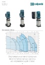
Каталог вертикальных многоступенчатых насосов Calpeda серий MXV, MXVL, MXV EI 2026. pdf, 7.05 Mb
Модели: MXV 25, 32, 40, 50, 65, 80, 100, MXVL 65, 80, MXV EI. Каталог серии: область применения, конструкция и материалы, рабочие характеристики и кривые, габаритные размеры и масса. -

Каталог осевых вентиляторов Shuft серии AXW. pdf, 4.05 Mb
Модели: AXW 4E–8DY с типоразмерами 200–910 в исполнениях S-G, S-T, B-T, B-P. Технический каталог модельного ряда: расшифровка обозначения, характеристики, схемы подключения, аэродинамические графики и габаритные чертежи. -
Каталог продукции Пульсар 2026 - Дренажные насосы. pdf, 3.91 Mb
Каталог продукции Пульсар 2026 - Дренажные насосы
Новое в инструкциях
-
Циркуляционные насосы KSB серии Calio. pdf, 7.92 Mb
Руководство по эксплуатации и монтажу высокоэффективных циркуляционных насосов Calio (оригинальное руководство KSB, док. 1157.821/13): техника безопасности, описание, установка и монтаж, ввод в эксплуатацию, управление и настройка, техобслуживание, неисправности и их устранение, схемы электрических подключений. -
Секционные насосы высокого давления KSB серии Multitec и Multitec-RO. pdf, 8.34 Mb
Модели: Multitec, Multitec-RO, типоразмеры 32–250, исполнения A, B, C, D, E, V. Руководство по эксплуатации и монтажу высоконапорных секционных насосов: техника безопасности, транспортировка и хранение, описание, установка и монтаж, ввод в эксплуатацию, техобслуживание и текущий ремонт, неисправности и их устранение, прилагаемая документация (разрезы, схемы подключения). -
Канальные шумоглушители Shuft серии SCr. pdf, 450.17 Kb
Модели: SCr 100/600 – SCr 500/900 (диаметры 100–500 мм, длина шумоглушащей части 600 и 900 мм). Объединённый эксплуатационный документ (паспорт) на канальные шумоглушители для круглых воздуховодов: назначение и условия эксплуатации, расшифровка обозначения, характеристики и размеры, акустические характеристики, монтаж и эксплуатация, техническое обслуживание, условия гарантии.