

Инструкция на Руководство по монтажу автоматики C8 приточно-вытяжных установок DOMEKT: подключение, электрические схемы, ввод в эксплуатацию. Документ на английском языке.
Руководство пользователя автоматики C6M установок DOMEKT: функции, управление с пульта и через веб-интерфейс, настройки, неисправности и их устранение. Документ на английском языке.
Смотрите также: Инструкция по транспортировке, монтажу и эксплуатации →
Загружаем документ…
Текст инструкции
-
komfovent
DOMEKT C6M AUTOMATION USER MANUAL
-
LT – Prieš montuodami vėdinimo įrenginį atsisiųskite „Montavimo instrukciją“ / EN – Before installing air handling unit download „Installation manual“ / CZ – Před instalací vzduchotechnické jednotky si stáhněte „Instalační příručku“/ DA – Før installation af luftbehandlingsenheden, download…
-
1. INTRODUCTION
The air handling unit is designed to ensure good ventilation of premises. Air handling unit removes indoor air containing carbon dioxide, various allergens or dust, while replacing it with filtered fresh air from outside. As the outside air is usually colder or warmer than the air within the…
-
2.2. Temperature control
Temperature in the air handling unit is maintained by measuring the actual temperature and comparing it to the user-defined temperature. Then, depending on whether the supply air requires heating or cooling, heat exchanger or additional heaters/coolers are activated. Available temperature control…
-
2.5. ECO mode
ECO – an energy saving mode intended for minimizing power consumption. Power consumption is reduced by turning off heating/cooling devices, making maximum use of outdoor air or decreasing fan speed. During ECO mode: • Electrical heater is blocked, all other external air heating/cooling devices are…
-
Humidity control Humidity control function allows dehumidification of air in the premises. Possible ways of dehumidification: 1. If outdoor humidity is measured via an additional humidity sensor, air in the premises will be dehumidified when humidity level outdoors is lower than indoors. Indoor…
-
Counterflow heat exchanger frost protection1
The heat transfer and condensation occurring in the counterflow heat exchangers creates a possibility for it to freeze at low air temperatures. The air handling units have several measures to reduce the risk of freezing. On such units, when the outside temperature drops to -4°C, preheater…
-
3.1. Control panel C6.1
Panel with a colour touch-sensitive display. This control panel is designed for indication and changing of various functions and settings of the unit. If the unit is connected to the mains, the control panel will display home screen or a screen saver that you can switch off with a single tap.…
-
3.1.1. Parameter overview
Swipe the main window to the side to see various parameters: air flow, temperatures, filter contamination, energy recovery and power consumption. 16:30 16:30 16:30 Heat recovery OVERVIEW 4,23 kW 20,0 °C 21,7 °C 82% 10,4 °C Power consumption NORMAL 210 m3/h 210 m3/h 1,20 kW 17 % 0,87 kW ECO AUTO ECO…
-
3.1.3. Turning off
If you want your device to stop working, regardless the operation schedule and other functions, you can turn it off. To turn off the device: 1. Press “Menu” button at the bottom of the home screen. 2. Press the ON/OFF button at the bottom of the menu window. 3. Confirm the message that appears. 4.…
-
1. Press an icon indicating the current operation mode in the middle of the home screen. 2. Select and press a desired special operation mode. 3. Use the arrows to select desired operation duration and press to confirm. 4. Press the return icon at the top of the screen to return to the home screen.…
-
3.1.6. Airflow and temperature settings
You can set air flow for supply and exhaust air, desired temperature and turn off/on an electric heater for each ventilation mode. If turned off, the heater will not turn on even when the desired temperature is not reached. If turned on, the heater will operate only when a heat exchanger alone…
-
3.1.8. ECO mode activation and settings
ECO mode may be activated in any ventilation mode by pressing ECO button at the bottom of the home screen. For more information about the ECO mode see chapter “Air Quality Control Functions”. 16:30 ECO 5s ECO Heater blocking On Min. supply air temperature Cooler blocking On Max. supply air…
-
To create a weekly operation schedule
1. Select a weekly schedule “My week” as shown in Chapter “Mode Change”. 2. Press the centre of the schedule window and hold for 5 seconds. 3. Press the weekday row to select which days of the week this schedule sheet is valid for. 4. Press + symbol and add a new row. 5. Press the ventilation mode…
-
Screen saver – turn the screen saver on/off. Screen saver activates when a control panel is not used for longer than 1 min. You may select brightness of a screen saver, as well as settings and the order in which they are displayed. If a screen saver is deactivated, the control panel display turns…
-
3.1.11. Advanced settings
To access the advanced settings, press and hold the SETTINGS button for 5 seconds. Menu Overview Advanced settings 5s Advanced settings Temperature control Control sequence Flow control Connectivity Air quality control Filters Fire dampers Panel sensor calibration Scheduling Settings 1/2 2/2 Reset…
-
Flow control – select a method for air flow control (see Chapter 2.1). Selected CAV or DCV air flow control allows additional corrections of supply and extract air measurements, when the measured air volume does not match the actual one. This may also be due to design features of the duct system…
-
Control sequence – here you can activate additionally connected duct-mounted heating or cooling devices (see “Installation Manual”) that will operate only when a heat exchanger or electrical heater alone cannot reach a desired temperature. Control sequence Control sequence Stage 1 Electric heater…
-
Condensate prevention on R units has the following settings: On – Automatic condensate prevention is activated by default and will reduce ventilation intensity if needed (see “Advanced settings”). Off – Condensate prevention will not work and user-defined airflow will be maintained. Control sequence…
-
„Status“ line shows connection between AHU and internet
Disconnected – AHU is not connected to LAN or internet network. No internet access – AHU is connected to LAN network and communicates with router, but internet is not accessible. Connected – AHU has internet access. In the „Modbus RTU“ line, it can be selected what device is connected to the…
-
3.1.12. Alarms
Messages appearing during operation are indicated by a red warning symbol in the home screen. Device operation may be stopped given the severity of a fault message. To read a message, press OVERVIEW section in the menu. You can also delete current alarms or view a recorded history of faults (up to…
-
3.2. Control panel C6.2
Simple and user-friendly control panel for intuitive navigation and control of the unit. This control panel offers 4 standard operation modes (see Chapter 2.3) and switching ON/OFF with a touch of a button without any additional settings (settings are pre-set in the factory). This control panel is…
-
3.3. Control via smartphone
To control the unit via a smartphone, the “Komfovent Control” app is required. Before using the app, you will need to create an account and sign in. This can be done by visiting the control.komfovent.com website or directly within the app. Select language Portal Portal REGISTER LOG IN Lietuvių…
-
On your smartphone (the phone must have internet access), open the “Komfovent Control” app. If you are the owner of the ventilation unit, the built-in wizard in the app will help you add your first unit. To add a unit, you will need to scan a QR code, which can be found: • on the unit door; • on the…
-
3.3.2. Main functions of the “Komfovent Control” app
After launching the app, you will first see the list of units assigned to you. Here you can add more units, change the app language, delete a unit, or rename it. To access the unit control interface, tap its image in the list. My devices Add a new unit, change the app language, or log out of the…
-
3.4. Internet control
The unit can be controlled via the Internet using a computer on the website control.komfovent.com or a smartphone with the “Komfovent Control” app. Before controlling the unit, you will need to create an account and register. This can be done by visiting the control. komfovent.com website or…
-
• • The unit ID can be found: next to the QR code on the unit door; on the main control board (see “Installation manual”); on the control panel (see section “3.1.13. About the unit”). You will see all units you have added and those shared with you in the list. To control a unit, simply click on the…
-
3.5. Control via a computer without an internet connection
The device can also be controlled from a computer within a local network (without internet) or by connecting to it directly. For information on connecting the unit to an internal network or directly to a computer, see the “Installation Manual”. Enter the device IP address in your web browser (IP…
-
3.5.1. Turning on/off and changing operation modes
Press any ventilation mode button to turn on the device. The unit starts operating and the button of the activated mode changes its colour. To stop the device, press the TURN OFF at the top of the main window: CONTROL OPERATION CONTROL OPERATION MODES ECO AWAY NORMAL INTESIVE BOOST KITCHEN FIREPLACE…
-
3.5.3. Airflow and temperature settings
You can set air flow of supply and exhaust air, desired temperature and turn off/on an electric heater for each ventilation mode. If turned off, the heater will not turn on even when the desired temperature is not reached. If turned on, the heater will operate only when the heat exchanger alone…
-
3.5.5. Ventilation by a weekly schedule
To activate ventilation by a weekly schedule, press AUTO1 and select a desired operation schedule in the SCHEDULING section. Button of the selected schedule will change its colour. SCHEDULING SCHEDULE OPERATION PROGRAM 4:00 WORKING WEEK 8:00 12:00 16:00 20:00 24:00 STAY AT HOME I II OFFICE CUSTOM…
-
3.5.7. Alarms
In case of any fault messages during operation of the unit, a red exclamation mark will appear near the “Alarms” button. Device operation may be stopped given the severity of a fault message. Press the button ALARMS to read a message. You can also delete current messages or view a recorded history…
-
After changing any settings, press SAVE CHANGES to apply new values
To discard changes, return to the start window by pressing the return button. Button RESTORE SETTINGS restores all settings to the factory defaults. Be careful not to press this button accidentally. • • • The following sections are displayed in the settings window: USER INTERFACE – you can use it to…
-
Wrong value of indoor humidity may cause antifreeze protection to malfunction
• Numbers indicate the order of activation. All units have an integrated electrical heater, therefore it is factory-assigned as Stage 1. You can also assign an “external coil” (duct-mounted water heater/cooler) or an “external DX device” (direct evaporation unit) as a stage. If an external coil is…
-
• Device owner. If the unit has been added to an account by an unknown person (e.g. an installer or a previous occupant of the same dwelling with a ventilation unit), their account can be removed from the unit by pressing the “Remove” button. Remote assistance – by activating this feature, you can…
-
Code
1 Possible cause User‘s actions F6 Electric heater overheat Message 1. Supply air flow too low at high heating demand. 2. Power failure during operation of the electric heater; the heater could not cool down. 3. Electric heater malfunctioning. 1. a. Check air filters and air ducts. 1. b. Decrease…
-
Code
Message Possible cause User‘s actions W3 Return water temperature low Warning that the water temperature is lower than that required to heat the supply air. Check the condition of a circulation pump and the heating system as well as operation of a heating damper actuator. W4 Humidity sensor failure…
-
4.3. Remote control
If the ventilation unit is connected to the Internet, remote access to it can be provided to service representatives or a maintenance company if necessary. In the “Settings” menu, in the “Remote control” window, you will find the “Remote assistance” function. Remote assistance Permanent maintenance…
-
5. PERIODICAL MAINTENANCE
For proper operation of the air handling unit, it should be periodically inspected, the air filters replaced in due time and the interior of the unit cleaned. Some of the maintenance works can be performed by the user and others only by a qualified specialist. The operation, maintenance or repair of…
-
Airflow
direction ISO 16890 ePM1 60% n Air flo dir w ec tio ISO 16890 ePM1 60% Figure 1. A filter sticker indicating the direction of air flow In a ventilation unit, air always moves towards the center of the unit, so place the filters so that their arrow points towards the heat exchanger. Figure 2.…
-
Domekt R 400 H Domekt R 400 F 42 UAB KOMFOVENT we reserve the right to make changes without prior notice C6M_user manual_26-10
-
Domekt R 600 V
Domekt R 600 H Domekt R 700 H UAB KOMFOVENT we reserve the right to make changes without prior notice C6M_user manual_26-10 43
-
Domekt R 700 F Domekt CF 150 F 44 UAB KOMFOVENT we reserve the right to make changes without prior notice C6M_user manual_26-10
-
Domekt CF 350 V E1 Domekt CF 400 V UAB KOMFOVENT we reserve the right to make changes without prior notice C6M_user manual_26-10 45
-
Domekt CF 500 F
Domekt CF 700 H Domekt CF 700 F 46 UAB KOMFOVENT we reserve the right to make changes without prior notice C6M_user manual_26-10
-
Domekt CF 700 V
UAB KOMFOVENT we reserve the right to make changes without prior notice C6M_user manual_26-10 47
-
5.2. Device maintenance journal
The following table is for recording performed maintenance and repair works. The log is mandatory if the air handling unit is covered by the extended manufacturer’s warranty. Date 48 Performed procedures/notes Procedures performed by: Name, last name, signature UAB KOMFOVENT we reserve the right to…
-
APENDIX NO.1
KOMFOVENT CONTROL TERMS OF USE AND PRIVACY NOTICE 1. Introduction These Terms of Use (“the Terms”) govern the use of the KOMFOVENT CONTROL mobile application, operated by KOMFOVENT, UAB (“KOMFOVENT”), and the use of other related services. KOMFOVENT CONTROL is a mobile application designed to…
-
The processing of this data is necessary for the operation of the KOMFOVENT CONTROL app and provision of remote control services. If you use the KOMFOVENT CONTROL application, the legal basis for the processing of such data is the execution of the agreement on the use of the KOMFOVENT CONTROL mobile…
-
6. Notification and Termination
You may stop using the KOMFOVENT CONTROL app and/or stop periodical collection of your device information specified in point 5.3 Data Categories and Objectives at any time. This can be done in the KOMFOVENT CONTROL application by refusing to accept the Privacy Policy. By refusing to accept the…
-
APENDIX NO.2
WARRANTY INFORMATION Dear Customer, KOMFOVENT thanks you for your choice. We are pleased that you have chosen us and will strive to ensure you are satisfied with your purchased product. To avoid misunderstandings, we kindly ask you to read the installation and operating instructions of the product…
-
WARRANTY CONDITIONS
1. The warranty does not apply in the following cases: 1.1. If the product usage or operating conditions, as specified in the installation and operating instructions, are violated; 1.2. If the storage conditions of the unit are violated; 1.3. If there are signs indicating attempts of unqualified…
-
APENDIX NO.3
WHERE TO FIND SERIAL NUMBER? 1. On the unit casing AIR HANDLING UNIT S/N 123456 AHU-UNIT-MODEL-AND-CONFIGURATION Nominal voltage Nominal frequency Maximum current 230 V AC 50-60 Hz 6.5 A Serial No. 123456 IP54 Date of manufacture 2020.02.02 2. In the control panel Overview Overview Detailed…
-
komfovent
UAB KOMFOVENT we reserve the right to make changes without prior notice C6M_user manual_26-10 55
-
SERVICE AND SUPPORT
PARTNERS LITHUANIA UAB KOMFOVENT Phone: +370 5 200 8000 service@komfovent.com www.komfovent.com AT J. PICHLER Gesellschaft m. b. H. www.pichlerluft.at BE Ventilair group www.ventilairgroup.com ACB Airconditioning www.acbairco.be FINLAND Komfovent Oy Muuntotie 1 C1 FI-01 510 Vantaa, Finland Phone…
Схемы, таблицы и рисунки — в просмотре документа выше. Клик по номеру страницы открывает её в просмотре.
Новое в каталогах
-
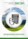
Каталог продукции Веза 2025 - Воздушные клапаны. pdf, 6.71 Mb
Каталог воздушных клапанов Веза: номенклатура, клапаны отсечные и регулирующие РЕГУЛЯР, РЕГУЛЯР-Л, РЕГЛАН, КЕДР и другие — конструкция, исполнения, приводы, технические характеристики, габаритные размеры. -
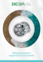
Каталог продукции Веза 2026 - Оборудование в морском исполнении. pdf, 7.62 Mb
Каталог вентиляционного и холодильного оборудования Веза в морском исполнении: радиальные и осевые вентиляторы, кондиционеры КОМПАС-БОВ, компрессорно-конденсаторные агрегаты КОМПАС-ККБ, шкафы управления КОМПАС-ШСАУ — технические характеристики и размеры. -
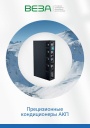
Каталог продукции Веза 2026 - Прецизионные кондиционеры АКП. pdf, 4.90 Mb
Каталог прецизионных кондиционеров АКП: назначение, исполнения, конструкция, технические характеристики, габаритные размеры, обозначение при заказе.
Новое в инструкциях
-
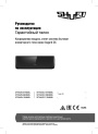
Инверторные сплит-системы Shuft серии Asgard DC. pdf, 8.78 Mb
Модели: SFTHAI/IN-07HN8/BL, 09HN8/BL, 12HN8/BL, SFTHAI/OUT-07HN8/BL, 09HN8/BL, 12HN8/BL. Руководство по эксплуатации: монтажная схема и монтаж, описание пульта управления и режимов работы, Wi-Fi и мобильное приложение, уход и обслуживание, технические характеристики, устранение неисправностей, протоколы приёмки и тестового запуска, гарантийный талон. -
Мобильные кондиционеры Shuft серии Frigo. pdf, 11.28 Mb
Модели: SFPAC-07 KF/N6, SFPAC-09 KF/N6. Руководство по эксплуатации: устройство и технические характеристики, управление кондиционером, монтаж, устранение неисправностей, самодиагностика, транспортировка и хранение, гарантийный талон. -
Прямоугольные канальные вентиляторы Shuft серии RF-B EC. pdf, 7.50 Mb
Модели: RFE-B EC 300x150 … 600x350, RFD-B EC 600x300 … 1000x500. Паспорт (объединённый эксплуатационный документ): описание, массогабаритные показатели, монтаж, подключение электропитания, схема электрического соединения, пуск, обслуживание, неисправности, гарантийные обязательства, технические данные.