

Инструкция на Автоматические коммутаторы (ATS) CyberPower
Автоматические коммутаторы (ATS) CyberPower серии PDU15SWHVIEC12ATNET/ PDU20SWHVIEC10ATNET/ PDU32SWHVCEE18ATNET обеспечивает простое и экономически эффективное резервирование электропитания 2N в стойке с однофазным оборудованием, обладает широкими функциями мониторинга и управления на уровне каждой розетки. Руководство пользователя.
Загружаем документ…
Текст инструкции
-
Automatic Transfer Switch
USER'S MANUAL Copyright © 2018 Cyber Power Systems, Inc. All rights reserved.
-
Overview
CyberPower Automatic Transfer Switches PDUs with dual input for power provide redundant and increased reliability for critical devices with a single power plug. Users can define the preferred input power source. When a selected source is unstable or unavailable, the ATS PDU will switch to the second…
-
Product Contents
For 1U Models ATS PDU Mounting Bracket x 2 24 (M4x8) Bracket Mounting Screws (Includes eight spares) Cord Retention Tray 4 (M3x4) Cord Retention Tray Mounting Screws 6 (M5x12) Rack Mounting Screws/ 6 Washers (Includes two spares for each) Cable Ties Qty.: 18 (NEMA Outlet) Qty.: 30 (IEC Outlet)…
-
Product Contents
For 2U Models ATS PDU Mounting Bracket x 2 24 (M4x8) Bracket Mounting Screws (Includes eight spares) Cord Retention Tray X 2 8 (M3x4) Cord Retention Tray Mounting Screws 6 (M5x12) Rack Mounting Screws/ 6 Washers (Includes two spares for each) Cable Ties Qty.: 30 (NEMA Outlet) Qty.: 50 (IEC Outlet)…
-
Front/Rear Panel Description (1U 15A Models)
A B C D E F G Source Output - Normal - Warning - Overload B Serial Port Enter PDU20SWHVIEC10ATNET QCN-0000003-00 NEMA Type SOURCE A Select A Expansion Port Provides SNMP Card Communication J SOURCE B 3 H 6 4 I IEC Type 9 10 J SOURCE B SOURCE A 8 K 1 H I K A. SNMP/HTTP Network Slot Allows users to…
-
Front/Rear Panel Description (1U 20A Models)
A B C D E F G Source Output - Normal - Warning - Overload B Serial Port Enter PDU20SWT10ATNET QCN-0000002-00 NEMA Type SOURCE A Select A Expansion Port Provides SNMP Card Communication J SOURCE B 1 H I IEC Type J SOURCE B SOURCE A 7 K 1 H I K A. SNMP/HTTP Network Slot Allows users to remotely…
-
Front/Rear Panel Description (2U 30A Models)
A C B D E F G Source Output A Select B1 - Normal - Warning - Overload B2 Expansion Port B Provides SNMP Card Communication B3 Enter PDU30SWT17ATNET QCN-0000005-00 Serial Port NEMA Type I SOURCE A BANK 1 (20A) BANK 3 (24A) SOURCE B BANK 2 (20A) L5-30R H K J IEC Type L I BANK 1 (20A) SOURCE A BANK 3…
-
Front/Rear Panel Description (2U 32A Models)
A C B D E F G Source Output A B1 B B2 Select - Normal - Warning - Overload Expansion Port Provides SNMP Card Communication Enter PDU32SWHVCEE18ATNET QCN-0000021-00 Serial Port I BANK 1 (20A) BANK 2 (20A) J H K L A. SNMP/HTTP Network Slot Allows users to remotely control and monitor the ATS PDU when…
-
ATS PDU Configuration
WARNING: This automatic transfer switch has dual power cords (A & B) to provide redundant power sources to devices with single power supplies and can be plugged into separate compatible sources* to ensure continuous access. Users select the preferred source as the primary input. CyberPower Smart App…
-
Please only use the provided screws for the entire installation process
Front Mounting For 1U Models Step 1. Mounting Bracket Installation Use the provided Mounting Bracket Screws (16) to attach the Mounting Brackets (2) to the ATS PDU. Step 2. Cord Retention Tray Installation (optional) Adjust the length of the Cord Retention Tray till the screw hole on the Tray and…
-
Front Mounting
Step 4. Cable Ties (Optional) Use the provided Cable Ties to fasten each cord to the Cord Retention Tray. For 2U Models Step 1. Mounting Bracket Installation Use the provided Mounting Bracket Screws (16) to attach the Mounting Brackets (2) to the ATS PDU. Step 2. Cord Retention Tray Installation…
-
Front Mounting
Step 3. ATS PDU Mounting Use the provided Washers (4) and Screws (4) to secure the ATS PDU to your existing rack system. Note: You may also use the screw sets provided by the rack to secure the ATS PDU. Step 4. Cable Ties (Optional) Use the provided Cable Ties to fasten each cord to the Cord…
-
If you plan on attaching the Cord Retention Tray to the ATS PDU, use
the provided Mounting Bracket Screws (8) to attach the Mounting Brackets (2) to the ATS PDU. Step 2. Cord Retention Tray Installation (optional) Adjust the length of the Cord Retention Tray till the screw hole on the Tray and ATS PDU are aligned. Attach the Cord Retention Tray to the ATS PDU with…
-
Step 4. Cable Ties (Optional)
Use the provided Cable Ties to fasten each cord to the Cord Retention Tray. For 2U Models Step 1. Mounting Bracket Installation Use the provided Mounting Bracket Screws (16) to attach the Mounting Brackets (2) to the ATS PDU. If you plan on attaching the Cord Retention Tray to the ATS PDU, use the…
-
Step 2. Cord Retention Tray Installation (optional)
Adjust the length of the Cord Retention Trays till the screw hole on the Trays and ATS PDU are aligned. Attach the Cord Retention Trays to the ATS PDU with the 8 supplied Cord Retention Tray Mounting Screws. Tighten the Cord Retention Trays with the screw on it. Step 3. ATS PDU Mounting Use the…
-
Replacing the LCD Panel
Step 1. Use a slotted screwdriver to gently lift out the LCD panel. Step 2. Disconnect the cable connector. Electrical Installation Step 1. Receptacle evaluation Ensure that the plug type of your ATS PDU unit matches the receptacles that you are using. The ATS PDU must be plugged into a three-wire…
-
Power Cord Locking - For IEC Type ATS PDU
Input Power Cord Step 1. Align and insert the Cable Tie from the upper side of the Fixed Stand and fasten it as shown below. Step 2. Align and insert the Cable Tie from the bottom side of the Fixed Stand and fasten it as shown below. Output Power Cord Step 1. Align and insert the Cable Tie from the…
-
Network Installation
(Performed when a Remote Management Card is installed) Step 1. Attach the LAN Cable Using a CAT5 RJ45 cable, attach one end to the Ethernet port on the RMCARD, and the other end to a network port. Step 2. Establish the ATS PDU IP address Assigning an IP address to the CyberPower ATS PDU requires the…
-
Operation
Remote Management The remote management function via the RMCARD205 provides for monitoring of the ATS PDU operational information, controlling outlets and utilizing SNMP functionality. Web Remote management can be performed via web interface. To access the web interface, please follow the…
-
Operation
Local Management Reset All (ATS PDU, RMCARD and LCD) Reset Except TCP/IP Reset/Reboot Reset Account (User Name and Password) Reboot LED Indicators Indicator Source Load Tx/Rx Status Description Solid Green Selected source and power condition is normal. Flashing Green Backup source and power…
-
By upgrading the Firmware, you can obtain new features, updates and
improvements to existing functionality. To ensure the firmware is kept up to date, please regularly visit our website to see if there is any updated firmware version available. Note: Please do not turn the ATS PDU off when processing the firmware upgrade. ATS PDU outlets will remain powered on while…
-
6. Select Transfer > Send File
7. Note that the Ymodem protocol and file “C:\cpsatsmafw_xxx.bin” are selected in Hyper Terminal. 8. The download progress window will open after you click the Send button. 9. After uploading the binary file Hyper Terminal will show as below. LCD Update the following file to upgrade the firmware.…
-
4. The ATS PDU will reboot and show main menu on Hyper Terminal
5. Press “2” to select LCD upgrade. 6. Press “1”. 7. Select Transfer > Send File. 8. Note that the Ymodem protocol and file “C:\cpsatslafw_xxx.bin” are selected in Hyper Terminal. 22
-
9 The download progress window will open after you click the Send
button. 10. After uploading the binary file, Hyper Terminal will be shown as below. You can see if the firmware upgrade is successful by checking the “CyberPower System Firmware Version” after login. Note : 1. Please do not turn the ATS PDU off and ensure the quality of selected source power when…
-
(1) ftp
(2) ftp > open (3) To [current IP address of RMCARD] [port]; e.g., To 192.168.22.126 21 (4) Input USER NAME and PASSWORD (same as the administrator account in web user interface) 5. Upload the cpsrm2scfw_XXX.bin, type: ftp > bin ftp > put cpsrm2scfw _XXX.bin 6. Upgrade is now complete, type: ftp >…
-
Confirm Upgrade Firmware message window
8. If the firmware upgrade is implemented, you will see the Result in the main window, as shown in below figure. Firmware upgrade success in the main window Troubleshooting Problem Possible Cause Solution ATS PDU outlets 1. Breaker tripped do not provide 2. Power cord is not power to connected…
-
Conformance Approvals
FCC Warning WARNING!! This equipment has been tested and found to comply with the limits for a Class A Digital Device, pursuant to Part 15 of the FCC Rules. These limits are designed to provide reasonable protection against harmful interference in residential installation. This equipment generates…
-
Customer Service & Warranty
Limited Warranty Read the following terms and conditions carefully before using the CyberPower ATS PDU series. By using the Product, you consent to be bound by and become a party to the terms and conditions of this Limited Warranty. If you do not agree to the terms and conditions of this Warranty…
-
Appendix A-Hyper Terminal
Hyper Terminal software can be used for basic ATS PDU configuration. In order for Hyper Terminal to interact with the ATS PDU, the PC/server must be connected directly to the ATS PDU via the serial port with the included RJ45/DB9 serial port connection cable. It utilizes a text-based interface and…
-
Overview
The CyberPower Power Device Network Utility is an easy-to-use interface which is used for establishing IP addresses on CyberPower ATS PDUs. Installation Step 1. Download the Power Device Network Utility software available at www.cyberpower.com. Step 2. Select Next in the software wizard (Shown in…
-
Step 5. Select Finish to finalize the installation (Shown in Figure 4)
Figure 4 Launch Program To launch the Power Device Network Utility and get started, select Programs from the Start menu in Windows and locate the new folder and icons for Power Device Network Utility. Select Power Device Network Utility from the program folder (Shown in Figure 5). Figure 5. Power…
-
Figure 7. Windows Security Alert
Step 2. Assign a valid IP Address to the ATS PDU. With the appropriate device selected from the Equipment List, open the Network Settings menu (shown in Figure 8) [Tools=>Device Setup]. In the Device Network Setting Menu, enter a valid IP address, subnet mask, and gateway address to setup the ATS…
-
Cyber Power Systems, Inc
www.cyberpower.com K01-0000322-03
Схемы, таблицы и рисунки — в просмотре документа выше. Клик по номеру страницы открывает её в просмотре.
Новое в каталогах
-
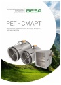
Каталог продукции Веза 2024 - Регуляторы переменного расхода воздуха РЕГ-СМАРТ для VAV-систем. pdf, 1.83 Mb
Каталог регуляторов переменного расхода воздуха РЕГ-СМАРТ для VAV-систем: назначение, конструкция, исполнения, технические характеристики, габаритные размеры, обозначение при заказе. -
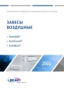
Каталог продукции Веза 2025 - Воздушные завесы. pdf, 4.97 Mb
Каталог воздушных завес Веза AeroWall, AeroGuard, AeroBlast: назначение, конструкция и исполнения, технические характеристики, габаритные размеры, подбор. -

Каталог продукции Веза 2026 - Оборудование для окрасочных камер. pdf, 5.13 Mb
Каталог оборудования Веза для окрасочных камер: центральные кондиционеры ВЕРОСА-600, вентиляторы радиальные и общепромышленные и другое оборудование — технические характеристики, габаритные размеры.
Новое в инструкциях
-
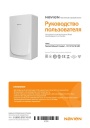
Газовые настенные котлы Navien серии Deluxe E Coaxial. pdf, 16.83 Mb
Модели: Deluxe E Coaxial 10K, 13K, 16K, 18K, 24K. Руководство пользователя (инструкция по эксплуатации и общие рекомендации по установке): устройство и основные элементы котла, панель управления, режимы отопления и ГВС, обслуживание, возможные неисправности и способы их устранения. -
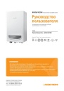
Газовые настенные котлы Navien серии Deluxe One. pdf, 11.23 Mb
Модели: Deluxe One 24K, 30K, 35K, 40K. Руководство пользователя (инструкция по эксплуатации и общие рекомендации по установке): устройство и основные элементы котла, панель управления, режимы отопления и ГВС, обслуживание, возможные неисправности и способы их устранения. -
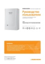
Газовые настенные котлы Navien серии Deluxe. pdf, 10.46 Mb
Модели: Deluxe 10K, 13K, 16K, 20K, 24K, 30K, 35K, 40K. Руководство пользователя (инструкция по эксплуатации и общие рекомендации по установке): устройство и основные элементы котла, панель управления, режимы отопления и ГВС, обслуживание, возможные неисправности и способы их устранения.