

Инструкция на Программное обеспечение CyberPower PowerPanel® Battery Management
Программное обеспечение CyberPower PowerPanel® Battery Management для управления батареями с мощным инструментом анализа данных. Это серверное программное обеспечение, позволяющее пользователям получать удаленный доступ через веб-браузер для мониторинга и управления системой батарей. Руководство пользователя.
Загружаем документ…
Текст инструкции
-
USER’S MANUAL
PowerPanel® Battery Management Rev. 1 SAVE THESE INSTRUCTIONS Please read this manual and follow the instructions for installation and use. Copyright © 2019 Cyber Power Systems, Inc. All rights reserved.
-
Chapter 1 Overview
Keeping 100% system uptime is crucial for today’s businesses. Batteries are used to provide critical backup power to maintain normal operation when power failure happens. CyberPower Battery Management System provides a proactive approach to manage and monitor a battery system attached to a network…
-
Figure 1.1 Application Scenario
-
Chapter 2 Getting Started
2.1 Prerequisites 2.1.1 Hardware Requirements For 5,000 Batteries • Higher than Core 4-compatible CPU. • Minimum of 16GB RAM recommended; more memory generally improves responsiveness. • Minimum of 300GB free space. 2.1.2 Operating System 64-Bit Versions: • Windows Server 2012 R2 (Need to update to…
-
Installation 1. Click to open the PowerPanel® Battery Management installation file. 2. Follow the on-screen prompts to install PowerPanel® Battery Management: (1) Click Next to continue. (2) Select the installation folder and Start Menu folder then click Next. 4
-
(3) Check the windows operating system version
(4) The installation begins. 5
-
(5) When the installation has completed, click Finish
-
Opening PowerPanel® Battery Management There are three ways to open PowerPanel® Battery Management: 1. Go to Start > Search bar > PowerPanel Battery Management. 2. In the localhost, type http://127.0.0.1:3000 into browser search bar. 3. In the client, type http://localhost_IPaddress:3000 into…
-
Chapter 3 Using PowerPanel® Battery
Management 3.1 Log in After opening the PowerPanel® Battery Management in the web browser, enter a Username and Password to log in. See Figure 3.1. The default username and password are admin/admin. Figure 3.1 Log in page 8
-
Understanding the User Interface The figure below (Figure 3.2) shows the main user interface of PowerPanel® Battery Management. The web page can be split into four areas and the features are described in Table 3.1. Figure 3.2 User Interface Table 3.1 Main Interface Feature description No Description…
-
Add a BM into PowerPanel® Battery Management To monitor batteries, add the BM into the PowerPanel® Battery Management first. Follow below steps to add and set up a BM. 1. Go to Settings > BM. Figure 3.3 Settings > BM page 2. Select Add to add a BM by entering the BM device’s IP (Figure 3.4), or…
-
Figure 3.4 Add function on BM page
Figure 3.5 IP Range function on BM page 3. Click Save, the progress bar will show at the top of the page. 4. When the adding succeeds, the BM will be listed on the page. Click the triangle beside the BM to display its configuration (Figure 3.6). 5. Click to set the BM’s configuration and pair the…
-
to Settings > UPS List and add UPS (Figure 3.8). See 3.9.2 for the
details. 6. Go to Dashboard and start to monitor the batteries (Figure 3.9). System allows 25 BM devices installed in PowerPanel® Battery Management for free, and each BM supports 4 strings of 50 batteries each (totally 200 batteries). Note: When the BM is added successfully, PowerPanel® Battery…
-
Figure 3.8 Add UPS
Figure 3.9 Dashboard-BM Monitoring 13
-
Monitor the Battery PowerPanel® Battery Management builds clear device structure to display multiple BMs in Dashboard (Figure 3.10). PowerPanel® Battery Management also defines three colors to show different device status. The details of status are described in Table 3.2. Useful statistics are also…
-
The dashboard is split into distinct areas. On the top-left corner, the
numbers of total warning strings and warning batteries are displayed (❶ in Figure 3.11). On the left side, string list grouped by BM or UPS is displayed (❷ in Figure 3.11). Each device is displayed in colors to show its status. Users can easily spot a string that has a problem or view its string…
-
directly with the statistic on the top-left corner. Take Figure 3.12 for
example, 2 batteries and 1 string are in warning status. With this information, users can check the below device list to find out which BM and strings have problems. PowerPanel® Battery Management provides BM mode and UPS mode to display the string structure. Figure 3.13 and Figure 3.14 show the…
-
Figure 3.12 Battery Health in the whole system
Figure 3.13 BM Mode Figure 3.14 UPS Mode 17
-
Figure 3.15 Open the string list
Figure 3.16 The string voltage Figure 3.17 The string health 18
-
Figure 3.18 Battery monitoring value
Table 3.3 The string health statistic Statistic Description The ratio of the normal battery to the total battery. The ratio of the voltage normal battery to the total battery. The ratio of the impedance normal battery to the total battery. The ratio of the temperature normal battery to the total…
-
Figure 3.19 Measure function
The Measure feature is used to display real-time battery values of the string. There are three bar charts to display the battery value of the string with different parameters. The different parameters are displayed in distinct colors. Blue is for voltage, orange is for impedance, and green is for…
-
Figure 3.20 Measure function
In the bar chart, the X-axis is the battery number of the string. The black lines in the chart are the average parameter and the dotted lines are the parameter thresholds. However, there is no dotted line in the impedance bar chart because the batteries in the string may have different impedance…
-
Historical Trend One of the most important aims of PowerPanel® Battery Management is to check the power supply reliability of the batteries in order to maintain the power system’s stability. PowerPanel® Battery Management provides the History feature to help users review the battery performance by…
-
Figure 3.22 Distinct areas on History page
PowerPanel® Battery Management provides double Y-axis to analyze the relationship between two parameters. In the filter area, PowerPanel® Battery Management allows users to select two parameters (❶ in Figure 3.23), a particular battery (❷ in Figure 3.23) and decide the data period for analysis.…
-
Management also provides the data storage space analysis to help
users manage battery data (❹ in Figure 3.23). Figure 3.23 History Filter 24
-
Charge balance Each individual battery within a string may have differences which cause the different voltage level when it is being charged. The unbalanced voltage level in the string will minimize the power capacity and the battery lifespan seriously. To prevent this damage, PowerPanel® Battery…
-
Figure 3.25 Distinct areas on Charge page
After selecting a string, the voltage statistic is displayed in the String Detail. The String Detail description is shown in Table 3.5. If the battery voltage is far under or over the string average voltage, the battery health is bad. If a battery stays in severe voltage status for a long time, use…
-
Alert Events PowerPanel® Battery Management provides alert service to notify users of abnormal battery events. Users can set the alert level of each battery parameter and then PowerPanel® Battery Management will monitor and collect the parameter values every 10 seconds. If any parameter is out of…
-
Figure 3.27 Distinct areas on Alert page
PowerPanel® Battery Management will show all battery alert events happening in the past month in the default setting. However, PowerPanel® Battery Management allows user to select different conditions, such as the specified battery, event period, and so on. The filter items are described in Table…
-
Table 3.6 Alert filter items description
Item Description BM/UPS The modes of displaying the string structure. Time The time period of the alert events. State Treat Parameter Active: The alert event is underway. Inactive: The alert event is dismissed. Acked: The alert event has been acknowledged. Not Acked: The alert event has not been…
-
Report PowerPanel® Battery Management provides two types of periodic reports: Daily Report and Monthly Report. It calculates the analytical data from each BM for checking the battery performance during the time. 3.8.1 Daily Report Daily Report shows the daily information of the whole PowerPanel®…
-
Figure 3.31 Daily report
-
3.8.2 Monthly Report
Monthly Report shows the monthly information of the whole PowerPanel® Battery Management. It calculates the data at the end of the month and sends out report according to the sending time. See 3.9.8 for configuring the sending time. Monthly Report can be divided into three parts. First is the UPS…
-
Figure 3.32 Monthly report-1
-
Figure 3.33 Monthly report-2
-
Environment Monitoring PowerPanel® Battery Management supports environmental sensor, providing real-time monitoring and event alert to ensure the safety of the operational environment (Figure 3.34). Figure 3.34 Environment monitoring 3.9.1 Status The real-time information of environmental sensors is…
-
Figure 3.35 Environment status
3.9.2 Log PowerPanel® Battery Management records the environmental sensor data on the Log page every 10 minutes. There is a data filter to select the data from database (❶ in Figure 3.36) and then the data will be shown in the list on the right side (❷ in Figure 3.36). If the data is out of the…
-
Figure 3.36 Environment log
3.9.3 Event PowerPanel® Battery Management provides environmental sensor alert service to notify users of the abnormal environmental events. Users can set the alert level of each environmental sensor parameter and then PowerPanel® Battery Management will monitor and collect the parameter values…
-
Figure 3.37 Environment event
There are three types of events for the environment sensor. The typical event is evaluated with the parameter threshold. It may be recorded as over or under parameter in the list (❸ in Figure 3.38). If the dry contacted device is abnormal, it will also be recorded into Event (❶ in Figure 3.38). If…
-
Configure the PowerPanel® Battery Management In this section, all of the PowerPanel® Battery Management setting features are introduced and users can follow the description to maintain the PowerPanel® Battery Management’s normal operation. 3.10.1 General General feature allows users to change the…
-
Figure 3.40 UPS List
Table 3.7 UPS List function description Item Description Click to add a UPS into the PowerPanel® Battery Management. Click to edit the selected UPS in the table. Click to delete the selected UPS in the table. Table 3.8 UPS content description Item Description Name The displayed name of the UPS.…
-
3.10.3 BM
BM feature allows users to manage multiple BM devices. The BM page shows all BM devices in the table and users can click to edit the details or add a new device. Add BM There are two ways to add a BM into the PowerPanel® Battery Management. One is to click Add (❶ in Figure 3.41) and enter the BM’s…
-
3.44Figure 1.1). This configuration allows 200 batteries per string. The
other is to combine two strings in one (Figure 3.45). This configuration allows 100 batteries per string. Figure 3.41 BM Table 3.9 BM function description Item Description Click to add a BM into the PowerPanel® Battery Management. Click to delete the selected BM in the table. Click to add the BM…
-
Description
BM Name The displayed name of the BM. Merge String The configuration of the merge string function. String Using Number of used strings in the BM. Battery Using on a String Number of connected batteries per string. Equalization Turn the equalization feature on or off. Impedance Period The impedance…
-
Figure 3.43 Merge String
Figure 3.44 All strings merging in one string Figure 3.45 Two strings merging in one string 44
-
3.10.4 Threshold
Threshold feature is used to set the upper and lower bound values of the parameter for the normal value judgment. First, select the string and parameter for setting (❶, ❷ in Figure 3.46). Then type the upper and lower bound values and the result will show in the graphic on the right side…
-
3.10.5 Email
PowerPanel® Battery Management will send the report and alert events to the users by email. Email feature allows users to manage the mail server and the recipients to complete the email configuration. To setup the email server, select Generic to use the SMTP mail server to send out the mail, or…
-
Figure 3.48 Gmail configuration
3.10.6 Security PowerPanel® Battery Management provides more prudent transfer protocol for users. Security feature allows users to change the transfer protocol in https (Figure 3.49). Figure 3.49 Security 47
-
3.10.7 Authorization
PowerPanel® Battery Management requires authorization to add the BMs. 25 BMs authorization with 4*50 scope has already been installed in the PowerPanel® Battery Management (Figure 3.50). If more authorization is required, please contact the support team and add the new authorization on this page.…
-
3.10.8 Report
PowerPanel® Battery Management provides two types of periodic reports: Daily Report and Monthly Report. Users can customize the report sending time in the Report function (Figure 3.51). Figure 3.51 Report 49
-
3.10.9 Envir
Envir feature allows users to manage multiple environmental sensors. The Envir page shows all environmental sensors in the table and users can click to edit the details Figure 3.52. The function details are shown in Table 3.11 and the environmental sensor contents are described in Table 3.12. Figure…
-
Description
environmental sensor. Location The location of the environmental sensor. Temperature High Threshold The reasonable upper boundary of the temperature. Low Threshold The reasonable lower boundary of the temperature. Rate of Change The tolerance of temperature variation in 5 minutes. Humidity High…
-
Figure 3.53 The door sensor configuration
-
Data Management Data Management allows user to export all battery data for further analysis (Figure 3.54). First, select a particular battery (❶ in Figure 3.54) and decide the data period (❷ in Figure 3.54). Then click Export to output the battery data (❸ in Figure 3.54). Figure 3.54 Data Management…
-
Cyber Power Systems, Inc
www.cyberpower.com For USA and Canada: 4241 12th Ave East, Suite 400 Shakopee, MN 55379 Toll-free: (877) 297-6937 For all other regions: Please visit our website for local contact information. Copyright © 2019 Cyber Power Systems, Inc. All rights reserved.
Схемы, таблицы и рисунки — в просмотре документа выше. Клик по номеру страницы открывает её в просмотре.
Новое в каталогах
-
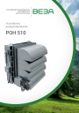
Каталог продукции Веза - Воздухоприемное устройство РОН 510. pdf, 1.96 Mb
Каталог воздухоприёмных устройств РОН 510: назначение, конструкция, технические характеристики, габаритные размеры, обозначение при заказе. -
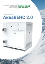
Каталог продукции Веза 2026 - Гидромодули АкваВЕНС 2.0. pdf, 1.29 Mb
Каталог гидромодулей АкваВЕНС 2.0: назначение, конструкция и исполнения, гидравлические схемы, технические характеристики, габаритные размеры, обозначение при заказе. -

Каталог продукции Веза 2026 - Вентиляторы осевые ОСА-ЭВО. pdf, 8.81 Mb
Каталог осевых вентиляторов ОСА-ЭВО: назначение, конструкция и исполнения, аэродинамические и технические характеристики, габаритные размеры, обозначение при заказе.
Новое в инструкциях
-
Конденсационные настенные газовые котлы Ferroli серии BlueHelix Tech S 45 H. pdf, 11.69 Mb
Руководство по эксплуатации, монтажу и техобслуживанию одноконтурного конденсационного котла мощностью 45 кВт (cod. 3541G103, Rev. 00 05/2017). Многоязычный документ с разделом на русском языке. -
Насосные станции Carel humiFog Multizone. pdf, 11.06 Mb
Руководство по эксплуатации насосных станций humiFog Multizone (+0300111ML, ред. 1.2): компоненты и схема системы, размещение и маркировка, монтаж, гидравлические и электрические подключения, пульт управления, обслуживание, аварийные сигналы. -

Электрические котлы Baxi серии Ampera Pro. pdf, 11.13 Mb
Руководство по установке и эксплуатации (паспорт изделия) электрических котлов AMPERA Pro: информация по безопасности, гарантия, технические характеристики, монтаж, электрические подключения и схемы, управление и настройка, коды ошибок, техническое обслуживание.