

Инструкции на Фэн-койлы универсальные Aqu@Fan, Aqu@Fan II.
Модели Aqu@Fan II 10-90 (AWC/AWN/AHC/AHN). Фэн-койлы универсальные. Руководство по установке и эксплуатации.
Смотрите также: Руководство по монтажу и обслуживанию →
Загружаем документ…
Текст инструкции
-
Installation and maintenance manual
Manuel d’installation et de maintenance Aqu@Fan II 10 ÷ 90 AWC AHC English AHN Français Fan coil units Ventilo-convecteurs IOM AQF-N.4GBF AWN Date : July / Juillet 2007 Supersedes / Annule et remplace : IOM AQF-N.3GBF/06.07
-
INSTALLATION INSTRUCTION
NOTICE D’INSTALLATION INSTALLATIONSHANDBUCH ISTRUZIONI INSTALLAZIONE INSTRUCCIONES DE INSTALACIÓN
-
POWER SUPPLY MUST BE
SWITCHED OFF BEFORE STARTING WORK IN THE ELECTRIC CONTROL BOX GENERAL RECOMMENDATIONS Please read the following safety precautions very carefully before installing the unit. SAFETY DIRECTIONS Follow the safety rules in forces when you are working on your appliance. The installation, commissioning…
-
INSPECTION AND STORAGE
At the time of receiving the equipment carefully cross check all the elements against the shipping documents in order to ensure that all the crates and boxes have been received. Inspect all the units for any visible or hidden damage. In the event of shipping damage, write precise details of the…
-
TECHNICAL SPECIFICATIONS
Size Power supply Fan motor power Fuse rating Am Fuse rating ASE / VDE Cable section mini without Electric heating 230V-50Hz ALTERNATIF 3G1.5 with Electric heating 230V-50Hz ALTERNATIF 1000 1500 1800 10 2250 12 2700 10 V W A A mm² Size Power supply 10 V Electric heating capacity BE1 Fuse rating Gg…
-
INSTALLATION
The unit is not designed to withstand weights or stresses from adjacent equipment, pipe work or constructions. Any foreign weight or stress on the unit structure could lead to a malfunction or a collapse with dangerous consequences for personnel and property. In such an event, the warranty shall be…
-
UNIT INSTALLATION
AWN / AWC CONSOLE UNIT All units are to be installed against a wall as a floor console with support feet, or wall mounting as per dimensional data. On the fan coil units equipped with support feet, we recommend you to fix the unit to the wall through the both oblong holes located on the upper part…
-
CABINET REMOVAL
When removing cabinet do not pull or lift it up by the discharge grilles, to avoid any damages on articulated fasteners of the access doors. On the AWC and AHC models, to hang the unit to the wall, it is necessary to remove the cabinet. To achieve this: Remove the fastener screws from the access…
-
WATER CONNECTIONS
OPERATING FACE The operating face of Left/Right versions is defined in relation to the position of the hydraulic connections when the unit is viewed facing the operator. Note: In the example below, the operating face is on the left. OPERATING FACE CHILLED WATER COIL - HOT WATER COIL Fan coil units…
-
WATER COIL HEADERS
Each water coil header has 1/2" female threaded pipe connection for water supply and water return. Do not push the coil headers to interior of unit casing, when tightening the screws of water connections. AIR VENTS AND DRAINS Coil headers have air vents and drains. Air vent is located at the upper…
-
ELECTRICAL CONNECTIONS
WARNING Before carrying out any work on the equipment, make sure that the electrical power supply is disconnected and that there is no possibility of the unit being started inadvertently. Non-compliance with the above instructions can lead to injury or death by electrocution. WIRING DIAGRAM AND…
-
OPTIONAL ELECTRIC HEATER
On request, all fan coil units can be factory mounted with an electric heater. The heating rod type electric heating is inserted directly into a finned exchanger. The latter may be a single block unit for sizes 10. 80. 90 or with an additional block for sizes 20 to 70. Do not install the electric…
-
UNIT INITIAL START-UP
After installing the fan coil unit, water and electrical connections being made, it is imperative to re-install the cabinet on the AWC and AHC fan coil unit. The cabinet will be fixed by the both screws, mentioned on section "Unit installation/Cabinet removal". Before initial start up, be sure that…
-
AIR FILTER
Changing the filter is a maintenance operation that should only be performed by qualified personnel. To avoid clogging of air filter, it is recommended to clean it regularly. Filter changes are required at the regular intervals. The time period between changes will depend upon the specific operating…
-
CONDENSATE DRAIN PAN
The condensate drain pan should be checked periodically and cleaned and rinsed if required. MODELS 20 TO 70: You can gain direct access to the condensates tray on non-encased units and after removal of the casing on encased units (See instructions in the chapter «Unit Installation / Casing removal)…
-
Take care
It is not the manufacturer's policy to make recommendations in terms of water treatment (please contact a specialised water treatment company). However, given the critical nature of this subject, particular care should be taken to ensure that, if treatment is required, it works effectively. Using…
-
APPENDIX
ANNEXE ANLAGE ALLEGATO ANEXO
-
APPENDIX
DIMENSIONS III AWC/AHC III AWN IV AHN IV VIEW OF MAIN COMPONENTS - AWC FAN COIL UNIT ..V WIRING DIAGRAM VI SE3530 10 - 90 CMV VII SE3531 10 - 90 CMV/TBV VIII SE3532 10 - 90 CMV/TBV1 IX SE3533 10 - 90 CMV/TBMV1 X SE3534 10 - 90 CMV/TBV XI SE3535 10 - 90 AQUANET XII SE3585 70 - 90 AQUANET + ELECTRIC…
-
DIMENSIONS
-
AWN
-
VIEW OF MAIN COMPONENTS - AWC FAN COIL UNIT
VUE DES PRINCIPAUX COMPOSANTS - MODÈLE AWC UBERSICHT - AWC-MODELL COMPONENTI PRINCIPALE – UNITÀ VERTICALI MODELLO AWC VISTA DE LOS COMPONENTES PRINCIPALES - UNIDAD FAN COIL AWC REP 1 Coil Batterie Register Batteria Batería 2 Discharge grille Grille de soufflage Ausblasgitter Griglia di mandata…
-
WIRING DIAGRAM
SCHEMAS ELECTRIQUES STROMLAUFPLANS SCHEMA ELETRICO ESQUEMA ELECTRICO TAKE CARE! These wiring diagrams are correct at the time of publication. Manufacturing changes can lead to modifications. Always refer to the diagram supplied with the product. ATTENTION Ces schémas sont corrects au moment de la…
-
> SE3530 10 - 90 CMV VII
-
SE3531 10 - 90 CMV/TBV VIII
-
таблицы и схемы — в просмотре
-
XI
> > > > SE3534 10 - 90 CMV/TBV
-
SE3535 10 - 90 AQUANET
> 12V > RCW RCW GND µBMS µBMS > XII
-
SE3585 70 - 90 AQUANET + ELECTRIC HEATING
12V > RCW RCW GND µBMS µBMS > XIII
-
> > > SE3537 10 - 90 XIV
-
4T
2-PIPE COILS 4-PIPE COILS COOLING HEATING BATTERIES BATTERIES 2 TUBES 4 TUBES FROID CHAUD LOW SPEED MEDIUM SPEED HIGH SPEED PETITE VITESSE VITESSE MOYENNE GRANDE VITESSE BATTERIEN BATTERIEN KÜHLUNG HEIZUNG KLEINE MITTLERE HOHE 2 ROHREN 4 ROHREN GESCHWINDIGKEIT GESCHWINDIGKEIT GESCHWINDIGKEIT…
-
S
-
таблицы и схемы — в просмотре
-
MODELE 40
MODELE 50 MODELE 60 MODELE 70 MODELE 80 MODELE 90 MONTAGE MONTAGE ALLEGE MURAL MONTAGE PLAFONNIER HORIZONTAL MODEL 40 MODEL 50 MODEL 60 MODEL 70 MODEL 80 MODEL 90 MOUNTING CONSOLE MOUNTING HORIZONTAL CEILING MOUNTING A40 A50 A60 A70 A80 A90 XVIII HORIZONTALE DECKENMONTAGE MONTAGGIO PLAFONIERA…
-
RIGHT
LEFT AIR FILTERS WITHOUT AIR FILTER STANDARD AIR FILTER $ G1 SERVICE SIDE SPEED CONFIGURATION WIRED SPEEDS WITHOUT HEATING BE1/BE2/BE3/BE4: HEATING capacity in W (example in this case: 300w) ELECTRIC HEATING D G V1.V2.V3 V1.V2.V4 V1.V2.V5 V1.V3.V4 V1.V3.V5 V1.V4.V5 V2.V3.V4 V2.V3.V5 V2.V4.V5 300W $…
-
XX
Q P N M L J H G F E D TBMV1 TBMV TBV1 TBV B CMV REP. ELECTRONIC / REGOLAZIONE REGULATIONS ELEKTRONISCHE / REGULACIONES ELECTROMECHANICAL ELECTRONIQUE / ELETTRONICA/ ELECTRÓNICA/ ELEKTROMECHANISCHE REGULATION ELECTROMECANIQUE ELETTROMECCANICA ELECTROMECÁNICA EINSTELLUNGEN BORNIER KLEMMENLEISTE…
-
4-WEGE-VENTIL / ALLES ODER VALVOLA 4 VIE / TUTTO O
NICHTS / 2 LEITUNGEN NULLA / 2 TUBI 4-WEGE-VENTIL / ALLES ODER VALVOLA 4 VIE / TUTTO O NICHTS / 4 LEITUNGEN NULLA / 4 TUBI 4-WAY VALVE / OPEN-CLOSE / VANNE 4 VOIES / TOUT OU 2 PIPES RIEN / 2 TUBES 4-WAY VALVE / OPEN-CLOSE / VANNE 4 VOIES / TOUT OU 4 PIPES RIEN / 4 TUBES 2-WAY VALVE / MODULATING…
-
XXII
FERNBEDIENUNG TELECOMANDO MANDO A DISTANCIA SCHNITTSTELLE INTERFACCIA TELECOMANDO INTERFAZ MANDO A FERNBEDIENUNG µBMS/RCW2 µBMS/RCW2 DISTANCIA µBMS/RCW2 TELECOMMANDE INTERFACE TELECOMMANDE µBMS/RCW2 INTERFACE (AIRCONET/ MODBUS) SONDE CHANGE OVER RELAIS CHAUFFAGE REMOTE CONTROL µBMS/RCW2 REMOTE…
-
EXAMPLE
EXEMPLE BEISPIEL ESEMPIO EJEMPLO A40.W.C.$.30.1000W.V1.V2.V4.G.G1.B.4V/TOR/2T.MPG.+ALV A40: MODEL 40 A40: MODELE 40 W: CONSOLE MOUNTING W: MONTAGE ALLEGE MURAL C: MODEL WITH CASING C: MODELE CARROSSE $: NO BRAND $: SANS MARQUE 30: 2P/3R COIL 30: BATTERIE 2T/3R 1000W: HEATING CAPACITY IN W 1000W…
-
XXIV
-
EC Compliance declaration
Under our own responsibility, we declare that the product designated in this manual comply with the provisions of the EEC directives listed hereafter and with the national legislation into which these directives have been transposed. Déclaration CE de conformité Nous déclarons sous notre…
-
As part of our ongoing product improvement programme, our products are
subject to change without prior notice. Non contractual photos. Dans un souci d’amélioration constante, nos produits peuvent être modifiés sans préavis. Photos non contractuelles. ACE Industrie Route de Verneuil 27570 Tillières-sur-Avre France : +33 (0)2 : +33 (0)2
Схемы, таблицы и рисунки — в просмотре документа выше. Клик по номеру страницы открывает её в просмотре.
Новое в каталогах
-

Каталог продукции Веза 2025 - Пункт тепловой индивидуальный БАЗИС, узел регулирующий ВЕКТОР. pdf, 8.85 Mb
Каталог индивидуальных тепловых пунктов БАЗИС, узлов регулирующих ВЕКТОР и блочных тепловых пунктов: назначение, схемы, комплектация, технические характеристики, габаритные размеры. -

Каталог продукции Веза 2024 - Регуляторы переменного расхода воздуха РЕГ-СМАРТ для VAV-систем. pdf, 1.83 Mb
Каталог регуляторов переменного расхода воздуха РЕГ-СМАРТ для VAV-систем: назначение, конструкция, исполнения, технические характеристики, габаритные размеры, обозначение при заказе. -
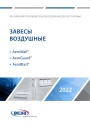
Каталог продукции Веза 2025 - Воздушные завесы. pdf, 4.97 Mb
Каталог воздушных завес Веза AeroWall, AeroGuard, AeroBlast: назначение, конструкция и исполнения, технические характеристики, габаритные размеры, подбор.
Новое в инструкциях
-
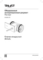
Воздушные клапаны Shuft серии DCGAr. pdf, 4.57 Mb
Паспорт (объединённый эксплуатационный документ) круглых воздушных клапанов DCGAr: назначение, описание, комплектация, характеристики, размеры и вес, монтаж и эксплуатация, обслуживание, гарантия. -

Осушители воздуха Shuft серии SBW. pdf, 1.08 Mb
Модель SBW 150A. Руководство по установке и эксплуатации настенного осушителя: принцип работы, параметры моделей, размеры, проводной контроллер и пульт ДУ, схема подключения платы, монтаж, обслуживание, коды ошибок. -

Твердотопливные котлы ZOTA серии Rio с контроллером C-Line. pdf, 2.23 Mb
Модели: Rio 16, 21, 26 кВт. Паспорт и руководство по эксплуатации твердотопливных котлов ZOTA Rio с контроллером C-Line, редакция от 20.04.2026: общие сведения, технические данные, комплект поставки, меры безопасности, устройство котла, размещение и монтаж, эксплуатация, техническое обслуживание.