

Инструкция на Чиллеры Airwell AQU@LOGIC AQH (с воздушным конденсатором и осевыми вентиляторами)
Модели AQH 20-130. Чиллеры с воздушным конденсатором и осевыми вентиляторами. Техническое руководство.
Смотрите также: Техническое описание →
Загружаем документ…
Текст инструкции
-
X Air-to-Water Reverse Cycle Heat Pumps
-
Why choose ILTC technology ?
The new range of Aqu@Logic air-to-water reverse cycle heat pumps comprises 14 models covering a nominal cooling capacity range from 20 to 131 kW and a nominal heating capacity range from 23 to 141 kW. As standard equipment, each unit has two compressors, fitted in tandem, for adapting to partial…
-
General specifications (continued)
Evaporator - Direct expansion type, made of brazed stainless steel plates. - The evaporator is surrounded by an electrical heating resistance and insulated with cellular polyurethane foam to provide anti-freeze protection down to an ambient temperature of - 20 °C. Air condenser - Comprising a heat…
-
ILTC control system
Display - Condensing pressure control is included as standard, thus enabling all Aqu@Logic units to operate between - 10 °C and + 46 °C. Condensing pressure control is provided by an algorithm, automatically managing the fan speeds operation. In partial load or low ambient outdoor temperature…
-
Refrigerant flow diagrams
Models 20 to 80 2 FH1 FPC CPT DIS 1 P C1 P P T 7 PED ON FPE EPT P P C2 Oil equalizer EWT 6 3 T P 4 T LWT 9 5 FS 8 Water inlet/outlet COMPONENTS C1/C2 compressors Condenser Filter - dryer Sight glass with moisture indicator Expansion valve Plate heat exchanger Four-way reverse cycle valve Liquid…
-
Refrigerant flow diagrams (continued)
Models 90 to C1 FH1 FPC CPT DIS 7 10 PED P P P FPE EPT P P T Oil equalizer 11 ON C2 EWT 6 3 T P 4 T LWT 9 5 FS 8 Water inlet/outlet COMPONENTS 1 C1/C2 compressors 2 Condenser 3 Filter - dryer 4 Sight glass with moisture indicator 5 Expansion valve 6 Plate heat exchanger 7 Four-way reverse cycle…
-
Selection guide
The following information is required for selecting the appropriate model : - Outlet water temperature : 6 °C. - Inlet water temperature : 11 °C. 1. Required cooling capacity in kW. - Outdoor air temperature : 30 °C. 2. Chilled water inlet / outlet temperatures. - Altitude : 0 m. 3. Outdoor air…
-
Selection guide (continued)
Operating limits (*) - Cooling mode Temperature min. Inlet water at start-up °C 10 Inlet water during running °C 10 Outlet water during running (without glycol) °C 5 Water temperature difference K 3 Working pressure bar Air °C -10 Operating limits (*) - Heating mode max Temperature min. Inlet water…
-
Technical characteristics - HFC 407C
AQH sizes Power supply (V / Ph / Hz) Cooling capacity (1) Heating capacity (2) Total power consumption with pump (3) Total power consumption (3) Total power consumption with pump (4) Total power consumption (4) COP Refrigerant charge Lw sound power levels Compressors Type Quantity Capacity reduction…
-
Technical characteristics - HFC 407C (continued)
AQH sizes Power supply (V / Ph / Hz) Cooling capacity (1) Heating capacity (2) Compressor power consumption (3) Total power consumption (3) Compressor power consumption (4) Total power consumption (4) COP - Cooling mode COP - Heating mode Refrigerant charge Lw sound power levels Compressors Type…
-
Technical characteristics - HFC 407C (continued)
Protection devices AQH sizes Fan thermal protection Compressors thermal protection Ancillaries / Fan circuit breakers Compressors circuit breakers Water pressure differential pressostat Water flow switch HP pressostat Evaporator anti-freeze protection HP transducer LP transducer yes yes yes yes yes…
-
Electrical characteristics - HFC 407C
Unit with hydraulic module AQH sizes Supply voltage (V / Ph / Hz) Permissible voltage Nominal power consumption Maximum power consumption Nominal current Maximum current Maximum starting current External fuse Cable section (100 m max.) kW 8.4 kW 10.0 A 18.3 A 21.3 A 65 A 25 mm2 6 10.0 14.2 21.5 29.3…
-
Performance data in cooling mode - HFC 407C
AQH sizes LCWT (°C) Pf Pabs 21.6 6.1 22.3 6.1 23.0 6.1 23.8 6.2 24.5 6.2 25.2 6.4 26.5 7.5 27.4 7.6 28.3 7.7 29.2 7.7 30.1 7.8 31.0 7.9 31.0 8.6 31.9 8.7 32.9 8.8 33.8 8.8 34.8 8.9 35.9 9.0 34.9 9.5 36.0 9.6 37.0 9.8 38.1 9.9 39.3 10.0 40.4 10.1 39.6 12.7 40.7 12.8 41.9 12.8 43.1 13.0 44.3 13.1 45.5…
-
Performance data in cooling mode - HFC 407C (continued)
AQH LCWT sizes (°C) Pf 87.6 90.2 92.9 95.5 98.4 101.1 99.3 102.3 105.2 108.3 111.4 114.4 115.2 118.7 122.1 125.6 129.2 132.8 123.4 127.1 130.6 134.3 138.1 141.8 131.1 135.1 139.3 143.4 147.7 152.0 30 Pabs 28.3 28.6 28.9 29.3 29.6 29.9 32.3 32.7 33.1 33.5 33.9 34.3 36.0 36.4 36.9 37.3 37.7 38.2 39.7…
-
Performance data in heating mode - HFC 407C
AQH sizes LHWT (°C) -5 -3 Pc 15.5 15.4 15.4 15.4 Pabs 5.5 6.2 6.9 7.6 Pc 17.0 16.9 16.8 16.6 Pabs 5.5 6.2 6.9 7.6 18.7 18.7 18.6 18.6 6.5 7.3 8.1 8.9 20.5 20.5 20.3 20.0 6.5 7.3 8.1 8.9 22.0 22.0 21.9 21.8 7.5 8.4 9.3 10.3 24.1 24.1 23.9 23.5 7.5 8.4 9.3 10.3 26.2 26.2 26.1 26.1 7.6 8.7 10.0 11.4…
-
Performance data in heating mode - HFC 407C (continued)
AQH sizes LHWT (°C) -5 Pc 68.2 68.2 68.5 69.1 69.7 75.3 75.8 76.6 77.4 77.6 87.5 87.7 87.7 87.5 87.2 95.1 95.4 95.6 95.7 95.7 100.0 100.0 100.0 99.8 99.5 Outdoor air temperature (°C) 0 5 -3 Pabs 24.5 27.1 30.2 33.7 36.4 27.9 31.2 34.7 38.6 39.8 29.9 33.1 36.6 40.2 43.8 32.3 35.8 39.6 43.8 47.7 34.0…
-
Unit external static pressure
Models 20, 25, 30 & kPa 0.40 25 0.60 0.80 1.00 1.20 1.40 1.60 1.80 30 2.00 2.20 2.40 Model 25 Model 30 Model 35 1.3 0.87 2.17 1.57 1.04 2.61 1.79 1.19 2.98 Water flow (l/s) Cooling mode Heating mode Water flow Model 20 (l/s) Nominal (1) 1.03 Minimum (2) 0.69 Maximum (3) 1.71 Model 25 Model 30 Model…
-
Unit external static pressure (continued)
Models 90 to kPa Water flow (l/s) Cooling mode Water flow Model (l/s) 90 Nominal (1) 4.13 Minimum (2) 2.75 Maximum (3) 6.88 Heating mode Model 100 4.68 3.12 7.80 Model 110 5.35 3.57 8.92 Model 120 5.84 3.89 9.73 (1) Eurovent conditions, Water : 12 / 7 °C, Air : 35 °C. (2) With water ∆t : 7.5 K at…
-
Heat exchanger water pressure drop
Models 20, 25, 30 & 35 250.00 20 200.00 25 150.00 kPa 30 / 35 100.00 50.00 0.00 0.00 0.50 1.00 1.50 2.00 2.50 3.00 3.50 Water flow (l/s) Models 40, 50, 60, 70 & 80 140.00 40 120.00 100.00 kPa 80.00 80 60.00 40.00 20.00 0.00 0.00 1.00 2.00 3.00 4.00 5.00 6.00 Water flow (l/s) Remark : the heat…
-
Heat exchanger water pressure drop (continued)
Models 90 to 130 1000 kPa Water flow (l/s) Remark : the heat exchanger water pressure drop curves are based on water average temperature of 10 °C. For temperatures different from 10 °C, use the correction factors as stated below : Water average temperature (°C) Correction factors Page 20 5 1.02 10…
-
Dimensions - Aqu@Logic AQH sizes 20, 25, 30 and 35
Front view Side view A D 173 161 C A - Water inlet Ø1 1/2" gas B - Water outlet Ø1 1/2" gas C - Ancillary electric cables entry D - Power supply cables entry 516 457(*) 1408 26 Top view 1607 B 9.5 18 1441(*) 1477 (*) Location of anti-vibration mounts. Dimensions in mm. Page 21
-
Dimensions - Aqu@Logic AQH size 40
Front view Top view (*) Location of anti-vibration mounts. Dimensions in mm. Page 22 Side view A - Water inlet Ø2" gas B - Water outlet Ø2" gas C - Ancillary electric cables entry D - Power supply cables entry
-
Dimensions - Aqu@Logic AQH sizes 50, 60, 70 and 80
Front view Top view Side view A - Water inlet Ø2" gas B - Water outlet Ø2" gas C - Ancillary electric cables entry D - Power supply cables entry (*) Location of anti-vibration mounts. Dimensions in mm. Page 23
-
Dimensions - Aqu@Logic AQH size 90
1374 Front view 1634 Side view 16.5 1201 2523 Side view Top view 1155 (*) 2363 A - Water inlet Ø2" gas B - Water outlet Ø2" gas C - Ancillary electric cables entry D - Power supply cables entry (*) Location of anti-vibration mounts. Dimensions in mm. Page 24
-
Dimensions - Aqu@Logic AQH sizes 100, 110, 120 and 130
1374 Front view 1634 Side view 16.5 1201 2865 Top view Side view 1155 (*) 23 2705 A - Water inlet Ø2" gas B - Water outlet Ø2" gas C - Ancillary electric cables entry D - Power supply cables entry (*) Location of anti-vibration mounts. Dimensions in mm. Page 25
-
Minimum clearance around the unit
-
FRANCE : 1 bis, Avenue du 8 Mai 1945 Saint-Quentin-en-Yvelines 78284 GUYANCOURT Cedex Tél. : +33-1 Fax : +33-1 www.airwell.com Tel. : 0 69/507 02-0 Fax : 0 69/507 02-250 www.airwell.de Tel. : 0362.6801 Fax : 0362.680281 www.itelco-clima.com Tel. : Fax : www.iberelco.es ACE Klimatechnik GmbH…
Схемы, таблицы и рисунки — в просмотре документа выше. Клик по номеру страницы открывает её в просмотре.
Новое в каталогах
-
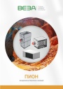
Каталог продукции Веза 2026 - Воздухонагреватели газовые ПИОН. pdf, 6.55 Mb
Каталог газовых воздухонагревателей ПИОН: назначение, конструкция и исполнения, технические характеристики, габаритные размеры, обозначение при заказе. -
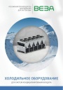
Каталог продукции Веза 2026 - Холодильное оборудование для систем кондиционирования воздуха. pdf, 4.97 Mb
Каталог холодильного оборудования Веза для систем кондиционирования: чиллеры, компрессорно-конденсаторные блоки, фанкойлы и другое оборудование — технические характеристики, габаритные размеры, обозначение при заказе. -
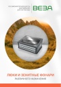
Каталог продукции Веза 2025 - Люки и зенитные фонари различного назначения. pdf, 8.45 Mb
Каталог люков дымоудаления и зенитных фонарей Веза различного назначения: конструкция и исполнения, приводы и автоматика, технические характеристики, габаритные размеры.
Новое в инструкциях
-

Полупромышленные канальные сплит-системы Shuft серии SFLC_D. pdf, 10.37 Mb
Модели: SFLC_D/in-18…60HN1_V2, SFLC_D/out-18…60HN1_V2. Руководство по эксплуатации: устройство, проводной пульт, монтаж, электрические схемы подключения, размеры, технические характеристики, устранение неисправностей, протоколы приёмки и тестового запуска, гарантийный талон. -

Полупромышленные напольно-потолочные сплит-системы Shuft серии SFLC_CF. pdf, 8.93 Mb
Модели: SFLC_CF/in-18…60HN1_V2, SFLC_CF/out-18…60HN1_V2. Руководство по эксплуатации: устройство, проводной пульт, монтаж, электрические схемы подключения, размеры, технические характеристики, устранение неисправностей, протоколы приёмки и тестового запуска, гарантийный талон. -

Мульти-сплит-системы Shuft серии FMI. pdf, 4.82 Mb
Модели: внутренние блоки SFMS/I-07…18 HB FMI/N8/IN/WHITE, наружные SFMO/I-14…42 FMI-2…5/N8/OUT. Руководство по эксплуатации: технические характеристики, управление кондиционером, монтаж, техническое обслуживание, поиск и устранение неисправностей, возможная комплектация блоков, гарантийный талон.