

Инструкция на Мобильные кондиционеры Airwell Aelia
Мобильные кондиционеры Airwell с электронной системой управления и дистанционным пультом, с электромеханической системой управления. Руководство по установке и эксплуатации.
Смотрите также: Инструкция по монтажу и эксплуатации →
Загружаем документ…
Текст инструкции
-
FRANGAIS
-
English
MOBILE SPLIT AIR CONDITIONER ELECTRONIC / REMOTE CONTROL ELECTRO MECHANICAL CONTROL INSTALLATION AND OPERATING INSTRUCTIONS
-
INTRODUCTION
This new split mobile air conditioner consists in an indoor and outdoor unit, interconnected by a flexible hose. The indoor unit is equipped with four castors for easy mobility. The air conditioner you have purchased is a factory-chagred and ready for use. No special installation is required; just…
-
DESCRIPTION
Electro-Mechanical models 3.1 KW (R407C) Electronic models 3.1 KW (R407C) Figure 1: Indoor and Outdoor Unit components Description (Front) Electro-Mechanical models 4.1 KW (R22/R410A) 3.1 KW (R410A) Electronic models 4.1 KW (R22/R410A) 3.1 KW (R410A) Figure 2: Indoor and Outdoor Unit components…
-
Models 3.1 KW (R407C) - With Quick Connectors Models 3.1 KW (R407C) Models 4.1 KW (R22/R410A) - With Quick Connectors 3.1 KW (R410A) - With Quick Connectors Models 4.1 KW (R22/R410A) 3.1 KW (R410A) Figure 3: Indoor and Outdoor Unit components Description (Back) 7. Spacing stud holes 8. Drain tube…
-
INSTALLATION
This mobile split air conditioner can be installed by the customer, as follows: Choose an appropriate place for the air conditioner indoor unit near an exterior opening (window or door). A grounded 230 electrical outlet should be within 2.5 meters of the indoor unit. Determine whether the outdoor…
-
INSTALLATION OF OUTDOOR UNIT (See Figure 6,7,8)
A standard kit (Figure 8), supplied with the air conditioner for suporting the outdoor unit, makes it possible to mount it either from a window sill (Figure 6) or on the wall (Figure 7), refer to Figure 8 for reference numbers in the following steps. 1. Install the 4 spacing studs (1) at the back of…
-
Figure 9
Prepare a slot in the lower part of door or window frame for the interconnecting hose location (see Figure 9). Pass the interconnecting hose which contains the refrigerant tubing, cable and drain tube through a window or door opening. Be sure not to subject the interconnecting hose to any…
-
APPLICATION OF QUICK CONNECTORS (OPTIONAL)
The quick disconnect feature is used when installing the flexible interconnecting hose through a window or a wall. It enables temporary separation between indoor and outdoor units when passing the hose through and opening in an external wall. DISCONNECTING THE UNITS (See Figures 10 and 11) To…
-
CONNECTING THE UNITS (See Figures 12 and 13)
After locating outdoor and indoor unit in their respective places, perform the following steps to reconnect between the two units: STEP 1. Remove protection plugs (16), (18) and covers (15), (17) from their respective connectors (see Figure 13). STEP 2. Connect quick disconnect (5) to its mating…
-
QUICK CONNECTORS APPLICATION (OPTIONAL)
English 10
-
OPERATION - ELECTRONIC MODEL (With remote control)
In order to obtain maximum comfort and economical operation, please make sure to: Doors and windows of room to be conditioned are closed. Air outlet and inlet openings on the unit are free of any obstruction. Shade the room from direct sunrays and avoid excessive sources of heat in the room. MODES…
-
VERTICAL AIR SWING (OPTIONAL)
Automatic swing of air supply in a vertical direction. The flaps automatically move in upward and downward directions to disperse the conditioned air evenly throughout the room. FILTER AND WATER OVERFLOW INDICATION (see indicator C on figure 15) Filter indicator on the indoor unit display is turned…
-
USE OF WIRELESS REMOTE CONTROL
THE WIRELESS REMOTE CONTROL BRINGS ALL FUNCTIONS TO YOUR FINGERTIPS. PRIOR TO OPERATION Prior to operating your air conditioner, make sure that: The unit is properly connected to the power supply. The red tab protecting the remote control battery has been removed. For clock settings, see page 18.…
-
ON-UNIT INDICATORS AND CONTROLS - (ELECTRONIC MODES) (See Figure 15)
A. TIMER INDICATOR E Lights up during TIMER and SLEEP operation. B. OPERATION INDICATOR D Lights up during operation. Blinks to announce that the remote control infrared signal has been received and stored. Blinks continuously when compressor operates in its high-pressure protection mode. Lights up…
-
REMOTE CONTROL (See figure 16)
START/STOP button 2 Operation MODE selection button 3 FAN SPEED and AUTO FAN button 4 Temperature set UP button (+) 5 Temperature set DOWN button (-) SLEEP button Automatic Vertical Air Swing button 8 TIMER select button 9 TIMER set up button (+) 10 TIMER set down button (-) 11 LCD display 12…
-
OPERATION PROCEDURE (See figs. 15 & 16)
TURNING ON THE AIR CONDITIONER Press START/STOP button (1) to turn on the air conditioner. Operation Indicator (B) on the air conditioner will light up, indicating that the unit is in operation. Note that the LCD operation display (11) will always show the last mode of operation and the previous…
-
AUTOMATIC VERTICAL AIR SWING
7 Press button (7) to activate the auto air swing. Press the button again to deactivate this function. 2 HEATING OPERATION * Select the HEATING mode by pressing MODE button (2). Switch to the desired Fan Speed or to AUTO FAN by pressing the Fan button (3). Select suitable temperature setting. (see…
-
CURRENT CLOCK TIME SET
Clock setting is performed when batteries are inserted. The remote control displays the setting, and the clock display will blink "00:00" or "12:00" until a new time is set. For clock setting, use buttons (9) (10) in order to set the hours and minutes, respectively, and then press timer SET button…
-
TIMER OPERATING MODES
I. TIMER ON This mode enables you to set a time for starting its operation. Press the TIMER button (8) until the ON sign blinks. Starting time can be adjusted using the up and down buttons (9) and (10), respectively. Press SET button (13) to activate the timer. Example: Operation is restored at…
-
OPERATION - (For Mechanical Models)
The air conditioner has the following features: On-unit operation control Indicator control lights Warning light Thermostat ON UNIT CONTROL AND DISPLAY PANEL (See Figure17) In order to obtain maximum comfort and economical operation, please make sure to: Follow the instructions for Installation For…
-
OPERATING PROCEDURE
Plug the unit into a power supply, and the power supply indicator (C2) lights up. This indicates that the unit is ready for operation. TURNING ON THE AIR CONDITIONER Turn the selector switch knob (A) from OFF to any desired position. FAN OPERATION (VENTILATING) Turn the selector switch knob (A) to…
-
CARE AND MAINTENANCE
WARNING Before performing any maintenance procedure, make sure to dis connect the air conditioner from the power supply. One of the functions of the air conditioner is to filter the supplied air by collecting dust and dirt particles from the air. Your air conditioner is provided with a main filter…
-
AT THE BEGINNING OF THE SEASON
Make sure there are no obstacles blocking the flow of inlet or outlet air. Make sure the power supply is properly connected. CLEANING OUTDOOR UNIT CONDENSATE BASIN (See Figures 23 and 24) Remove the water basin (2) by unscrewing the four screws (3) on each side of the basin. Clean the basin with…
-
IMPORTANT NOTICES
This air conditioner has been manufactured for domestic environments and should not be used for any other purpose. Do not obstruct the air conditioner's air discharge and inlet. If repair is needed, contact only the nearest authorized service center; unqualified servicing is dangerous. This air…
-
BEFORE CALLING FOR SERVICE
Before calling for service, please check the following malfunctions and correct as needed. Should this fail to remedy the malfunction, contact your nearest authorized service center for qualified assistance. PROBLEM Unit does not operate. Operation indicator doesn't light up. CAUSE Power failure.…
-
PROBLEM
CAUSE SOLUTION Unit does not respond properly to remote control command. IR signal does not reach unit. Check for obstruction between unit and remote control; clear if needed. Distance between remote control and unit is too great or remote control unit is aimed at improper angle. Get closer to unit.…
-
P2000 SPLIT - CAT NO.453125500 / MULTILANGUAGE / REV. 01 11/2004
Схемы, таблицы и рисунки — в просмотре документа выше. Клик по номеру страницы открывает её в просмотре.
Новое в каталогах
-
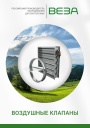
Каталог продукции Веза 2025 - Воздушные клапаны. pdf, 6.71 Mb
Каталог воздушных клапанов Веза: номенклатура, клапаны отсечные и регулирующие РЕГУЛЯР, РЕГУЛЯР-Л, РЕГЛАН, КЕДР и другие — конструкция, исполнения, приводы, технические характеристики, габаритные размеры. -
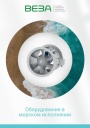
Каталог продукции Веза 2026 - Оборудование в морском исполнении. pdf, 7.62 Mb
Каталог вентиляционного и холодильного оборудования Веза в морском исполнении: радиальные и осевые вентиляторы, кондиционеры КОМПАС-БОВ, компрессорно-конденсаторные агрегаты КОМПАС-ККБ, шкафы управления КОМПАС-ШСАУ — технические характеристики и размеры. -
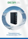
Каталог продукции Веза 2026 - Прецизионные кондиционеры АКП. pdf, 4.90 Mb
Каталог прецизионных кондиционеров АКП: назначение, исполнения, конструкция, технические характеристики, габаритные размеры, обозначение при заказе.
Новое в инструкциях
-
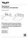
Компактные приточно-вытяжные установки Shuft серии UniMAX-P CE-A. pdf, 8.10 Mb
Модели: UniMAX-P 450 CE-A, 800 CE-A, 1000 CE-A, 1500 CE-A. Руководство по монтажу и эксплуатации подвесных установок с пластинчатым рекуператором и электронагревателем: характеристики, монтаж, схемы подключений, пусконаладка, пульт управления, техническое обслуживание, неисправности. -
Пульт управления АТБ-2400 для вентиляционных установок Shuft. pdf, 877.42 Kb
Модель АТБ-2400 (производство ООО «АТБ Электроника»). Руководство по эксплуатации настенного пульта: технические характеристики, подключение к контроллеру, главный экран, режимы, уставки, расписание, тревоги, обновление ПО, обслуживание. -
Компактные моноблочные приточные установки Shuft серии CAU W VIM. pdf, 5.89 Mb
Модели: CAU 4000-W VIM, CAU 6000-W VIM. Паспорт (объединённый эксплуатационный документ) установок с водяным нагревателем: описание, массогабаритные показатели, монтаж, схемы электрических соединений, схема обвязки, пусконаладка, обслуживание, неисправности, технические данные.