

Инструкция на Котлы конденсационные настенные Unical серии OSA S мощность 24 – 35 кВт. Руководство по монтажу и эксплуатации.
Смотрите также: Руководство пользователя →
Загружаем документ…
Текст инструкции
-
‘ee ons uae P 10 MPASSO RO Al $24-$28-5$ 35 + TOUCH CONTROL Ufly BOX integrate INSTALLATION AND SERVICING MANUAL ENGLISH
-
http://www.unicalag.it/prodotti/domestico-50/condensazione-gas/osa/1635/osa-s
Provisions for proper disposal of the product in accordance with Directive 2002/96/EC At the end of its life cycle the product must not be disposed of as urban waste. It can be taken to a special recycling centre managed by the local authorities, or to a dealer who offers this service. Separate…
-
GENERAL INFORMATION 1.1 - general warnings The instruction booklet is an integral and essential part of the product and must be kept by the user. Read the warnings contained in this instruction booklet carefully as they provide important guidelines regarding installation, use and maintenance safety.…
-
1.2 - SYMBOLS USED IN THE MANUAL
Pay special attention when reading this manual to the parts marked by the symbols: DANGER! Serious danger to safety and health ATTENTION! Possible dangerous situation for the product and the environment NOTE! Tips for the user NOTE! For more information See Technical Info: from site indicated at…
-
1.5 - SAFETY WARNINGS
Attention! The boiler cannot be used by children. The boiler can be used by adults and only after having carefully read the user’s manual. Children should be supervised to ensure that they do not play or tamper with the device. Attention! The appliance must be installed, adjusted and maintained by…
-
The CE marking is affixed to each piece of equipment with an appropriate label
The CE declaration of conformity issued in accordance with international standards by the manufacturer, is placed in documentation envelope supplied with the product. The rating plate is placed inside the boiler, The rating plate DUPLICATE is placed under the front casing (lower-right). KEY: 1 = CE…
-
1.7 - WATER TREATMENT
The treatment of the supply water allows to prevent inconveniences and maintain the functionality and efficiency of the generator over time. Attention! Any damage to the boiler caused by the formation of fouling or by corrosive water will not be covered by the warranty. The ideal water pH in heating…
-
TECHNICAL FEATURES AND DIMENSIONS 2.1 - TECHNICAL FEATURES NOTE! For more information See Technical Info from site indicated at pag. 2 ENGLISH 2.2 - VIEW WITH THE INDICATION OF THE MAIN COMPONENTS AND DIMENSIONS Technical Features OSA S 24 9
-
OSA $ 24 - OSA $ 28 - OSA $ 35
-
KEY
N° C.E. S.E. Description 26 Condensation drain trap 1 db SS Domestic hot water temperature sensor 33 Ufly BOX (retractable) FLS Flow switch with cold water filter 34 2 Gateway (external links) VG Gas valve 35 3 Emergency panel Aves Connection for additional expansion vessel C Domestic hot water…
-
2.3 - DIAGRAM OF FLOW RATE/PRESSURE AVAILABLE FOR
INSTALLATION MODULATING PUMP DIAGRAM OF FLOW RATE/PRESSURE AVAILABLE FOR INSTALLATION Technical Features Avaible Head (m.c.a.) metres of water ENGLISH OSA S 24 Flow rate (l/h) Avaible Head (m.c.a.) metres of water OSA S 28 - OSA S 35 Flow rate (l/h) 13
-
2.4 - OPERATING DATA ACCORDING TO UNI 10348
For the adjustment data: NOZZLES - PRESSURES - DIAPHRAGMS - FLOW RATES - CONSUMPTIONS refer to the paragraph ADAPTATION TO OTHER TYPES OF GAS. OSA S 24 OSA S 28 OSA S 35 Nominal heat input in CH / DHW mode kW 23,4 28,0 / 33,0 33,0 Minimum heat input with Nat. Gas / Propane kW 3,0 / 3,0 4,4 / 4,4 4,4…
-
2.4.2 - FEATURES OF INTEGRATED Ufly BOX
Ufly BOX control panel, togheter with room sensor temperature and outer sensor temperature provided as standard, performs the environmental thermoregulation work as described in the document 2014/C 207/02, section 6.1. ENGLISH Class VI – Weather compensator and room sensor, for use with modulating…
-
INSTALLATION INSTRUCTIONS 3.1 - GENERAL WARNINGS ATTENTION! This boiler is intended solely for the use for which it was expressly designed. Any other use is to be considered improper and therefore dangerous. This boiler heats water at a temperature lower than the atmospheric pressure boiling…
-
3.4 - PACKAGING
After having removed the appliance from the packaging, make sure that the supply is complete and undamaged. The packaging elements (cardboard box, straps, plastic bags, etc.) must be kept out of the reach of children as they are potential sources of danger. Unical AG S.p.A. will not be held liable…
-
3.5 - POSITIONING THE BOILER
When choosing the place of the installation of the appliance, follow the safety instructions below: - Place the appliance in rooms protected from frost. - Avoid installation in rooms with a corrosive or very dusty atmosphere. - The appliance must only be installed on a vertical and solid wall which…
-
3.6 - FLUE GAS EXHAUST PIPE CONNECTION FOR BOILERS WITH FORCED DRAUGHT
To connect the flue gas exhaust pipe, local and national standards must be observed In the event the boiler is replaced, ALWAYS re- place the flue gas pipe as well. The boiler is type approved for the exhaust configurations listed below: C13x C43x C13 C43 LT ENGLISH % % Slope towards inlet = 3%…
-
C63x
C63 B23P Boiler intended for connection to a combustion air intake and combustion products evacuation system, approved and sold separately ATTENTION: The flue must comply with standards in force. C83x C83 TOTAL LENGTH (LS) DOUBLE Ø80 FROM [m] TO [m] 1 30 Connection to a combustion products…
-
GENERAL INFORMATION ON THE FLUE GAS EXHAUST SYSTEM
Rubber sealing caps (Remove according to the type Exhaust used: HIGHER - Split (remove both) - Coaxial (leave only one shown) REAR NOT VISIBLE (rear in the boiler) installation instructions in the kit. it is possible only with coax (Leave 2 above). (+) Adapter for double systems Departure Coaxial…
-
3.7 - CONNECTION
G GAS 3/4’’ Danger! The gas connection must be carried out only by a qualified installer who must respect and apply that foreseen by relevant laws in force in the local prescriptions of the supply company. Incorrect installation can cause damage to persons, animals and objects for which the…
-
The connection between the appliance
and the domestic waste system must be made in compliance with the specific reference standards. NOTE! For more information See Technical Info from site indicated at pag. 2 3.8 - FILLING THE SYSTEM Note: The first fill of the boiler must be made manually. FILLING VALVE Screw in load position LOAD…
-
3.9 - ELECTRICAL CONNECTIONS
Danger! Only a qualified technician may perform the electrical installation. Before performing connections or any type of operation on electrical parts, always disconnect electrical power and make sure that it cannot be reconnected accidentally. The external connections have to be made on the…
-
SHC = Multifunction module (*)
- Arranged on GATEWAY connector, Y3 7-8. - Arranged on GATEWAY connector, Y3 4-3. ENGLISH SE = Outside sensor supplied Modulation Board INSIDE BOILER The boiler is equipped with a power cable, boiler installation requires electric al connection to the mains power supply. This connection must be made…
-
3.10 - COMMISSIONING
Commissioning must be done by professionally qualified personnel. Unical AG S.p.A. will not be held liable for damage to persons, animals or objects due to failure to comply with the above instruction. Before commissioning the boiler, check that: does the installation meet the specific standards and…
-
3.11 - MEASUREMENT OF COMBUSTION EFFICIENCY DURING INSTALLATION
3.11.1- ACTIVATION OF THE calibration function 1 - Insert psw and select sweeper again Vary % mod. request from 10 % to 100 % 2 - Activation 3- Chose burner among those available, eg: usually 1 / modulex (from 1 to 8). Note: once selected the burner, (3) the display page changes: Burner # 1 # 8 4…
-
5 - Burner operating to maximum power
(modulation 100%). 6 - Vary % of modulation request to the minimum 10% and select the burner 7 - Boiler operating with modulation min. (modulation 0%). 8 - Disable SWEEPER function. Exit by pressing Home icon. 3.11.2 - Positioning the probes To determine the combustion efficiency one must make the…
-
3.12 - ADJUSTING THE BURNER
Check the levels of CO2 often, especially with low flow rates. They refer to the boiler with a closed combustion chamber. PRESSURE - FLOW RATES TABLE Type of Gas Effective Output [kW] Heating Thermal [kW] Capacity Supply Press. [mbar] Fan speed [rpm] min Nat. gas (G20) Collector diaphragm [Ø/n.…
-
3.12.1 - COMBUSTION ADJUSTMENT FUNCTION ACTIVATION
This function allows a partial adjustment of the CO2 value on the following modulation points: Maximum output 100 % Start-up output xx % Minimum output 0 % After Auto Calibration GAC par. 4.3.1 Perform combustion adjustment calibration as indicated: If the CO2 value is not as expected, when appears…
-
ATTENTION!
Function reserved for Authorised Assistance Centres only. The user is NOT authorised to activate the function described below. It is possible to adjust the maximum thermal capacity in heating mode, by decreasing the burner pressure value. Act on parameter 792 (par. 4.2 SE parameters list) to achieve…
-
INSPECTIONS AND MAINTENANCE Inspections and maintenance performed professionally and according to a regular schedule, as well as the use of original spare parts, are of the utmost importance for fault-free operation of the boiler and to guarantee its long life. Yearly maintenance of the appliance is…
-
4.1.1- CONTROL PANEL Ufly BOX
General Operating Instructions for UflyBOX, are contained in specific manual provided with the boiler. ENGLISH This section only lists the steps required to Adjustment / maintenance of the boiler: - Chimney sweep function (Par. 3.11.1) - Calibration (Par. 3.12.1) - Edit parameters (Par. 4.2)…
-
ROUTINE YEARLY VERIFICATION OPERATIONS
COMPONENT: VERIFY: FL (domestic hot water priority flow switch ( 2 ) Is the minimum domestic hot water flow rate 3 l/min.? VG (Gas valve) ( 3 ) Does the valve modulate properly? SR (heating sensor)( 11 ) Do the sensors maintain the SS (domestic hot water sensor) original characteristics? (1) SSR…
-
ENGLISH
4.2 - PROGRAMMING OF THE OPERATION PARAMETERS WARNING! Function reserved exclusively to authorized service centers. At every boiler lighting UFLY scans devices, if new devices are recognized, such as: shc bmm Heating / Burner Control Manager Slave Heating Controller Multifunction module Burner Modul…
-
To change the parameters is required password
Parametri Code Description 803 Enabled Services: 0: CH & DHW disabled 1: CH enabled 2: DHW enabled 3: CH & DHW enabled Pump: Post-circulation 0: overrun 5 min. 1: continuous 0 787 Outdoor minimum temp °C Night shift °C 0: T.A. 5÷30: Value night shift 0 0/5 ACS Preheating Set. Min. Max. CH…
-
Unit
0 = °C / bar 1 = °Fahrenheit / PSI 0 806 Frequency: 0: 50 Hz - 1: 60 Hz Dis. local setpoint: 0: bidirectional 1: Only by remote Temp. different. Max 2590 Burner power -619 Modulation and ignition Min modulation CH/ACS Fan min speed (*) (**) Regolation Integrative ACS PID:Integrative ACS…
-
4.3 - ADAPTATION
TO THE USE OF OTHER GAS The boilers are produced for the type of gas specifically requested upon ordering. DANGER! The conversion for the operation of the boiler with a type of gas other than that specifically required in the order, must be performed by professionally qualified personnel, in…
-
4.3.1 - GAC AUTOMATIC CALIBRATION
One can perform the GAC in domestic hot water mode as well. Make sure that there are no heating requests present and that all the valves of the heating system are open. Start Calibration phase - Wait: Step 1 = Calibration Maximum Power Step 2 = Calibration Power Start Step 3 = Calibration Minimum…
-
Step 1: CALIBRATION MAX POWER
Step 2: CALIBRATION POWER START Step 3: CALIBRATION MIN POWER The automatic calibration is completed. To perform the calibration adjustment of combustion, see par. 3.12.1. 40
-
ENGLISH
-
KEY
BOARD BMM A1 A9 Services connectors ALIM. P. sup Supply. Pump Extra CMP Control modulating Pump E. ACC./RIL Ignition/detection electrode EVCI (*) Caricamento Impianto (Only OSA S) FLS Domestic hot water request flow switch MEMORY Memory CARD 42
-
MVD
MDV (**) PM SPI SR SRR SS TL TLC Diverter valve motor Control predisposition diverter (external water heater) only Heating boilers Circolatore Modulante Pressure Sensor System Flow heating sensor Return heating sensor Domestic hot water probe (Pred. for R models) Limit thermostat Flue gas collector…
-
4.5 - ERROR CODES
Failure that causes the stop of the boiler: Failure that could NOT cause stop of the boiler: - The error code is displayed, the boiler is in lock. After resolving the fault press Reset to restart the boiler. - Error code is displayed, the boiler is in CH demand, Icon Reset (note that was detected a…
-
Disconnect the from the power supply, close the Exchanger Freezing ( 24 ) Exchanger freezing is detected If the heating gas valve, defrost the exchanger carefully. sensor detects a temperature below 2° C, burner ignition is inhibited until the sensor detects a temperature above 5°C 20 Parasite Flame…
-
Gas valve wiring Frequent loss of flame Internal error General Lockout not listed Ignition failure Short circuit of the iono electrode Gas valve open delay
-
4.5.1 - FILL THE SYSTEM
By pressing reset icon, start the automatic filling, up to a pressure of 1.2 bar (60 sec. max). If the system does not reach 1.2 bar pressure within 60 seconds, activate the fill manually by pressing LOAD icon. 47
-
4.6 - IMPORTANT NOTES
REPLACING COMPONENTS Before replacing components one must follow the notes of chap. 4 "Inspections and maintenance". To replace the components: - GAS VALVE - FAN - BURNER, - IGNITION/DETECTION ELECTRODE, - MODULATION BOARD (in the event the memory board CANNOT be reused) (*), GAC calibration is…
-
4.6.1 - SERVICE PANEL
The boiler can be programmed also by means of the service inner panel. Remove the screws indicated to extract the panel and turn. Indications related to programming with the emergency panel, can be found at the address indicated on page 2, or on the user / installation manual and maintenance of KONE…
-
00336315 - 2nd. ed. 05/21
www.unical.eu AG S.p.A. 46033 casteldario - mantova - italia - tel. +39 0376 57001 - fax +39 0376 660556 info@unical-ag.com - export@unical-ag.com - www.unical.eu Unical declines every responsibility for the possible inaccuracies if owed to errors of transcript or press. Also reserves the right to…
Схемы, таблицы и рисунки — в просмотре документа выше. Клик по номеру страницы открывает её в просмотре.
Новое в каталогах
-
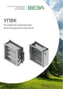
Каталог продукции Веза 2025 - Устройства перекрытия вентиляционных каналов УПВК. pdf, 1012.56 Kb
Каталог устройств перекрытия вентиляционных каналов УПВК: назначение, конструкция, технические характеристики, габаритные размеры, обозначение при заказе. -

Каталог продукции Веза 2025 - Шкафы систем автоматического управления ШСАУ ВЕРСА 100 - 400. pdf, 16.08 Mb
Каталог шкафов систем автоматического управления ШСАУ ВЕРСА 100–400: назначение, функции, исполнения, схемы, технические характеристики, обозначение при заказе. -

Каталог продукции Веза 2025 - Системы канальной вентиляции. pdf, 8.54 Mb
Каталог оборудования Веза для канальной вентиляции: канальные вентиляторы, нагреватели, охладители, фильтры, шумоглушители, клапаны — технические характеристики и габаритные размеры.
Новое в инструкциях
-
Электрические накопительные водонагреватели Royal Thermo серии Smalto Inverter. pdf, 9.20 Mb
Модели: RWH 30, 50, 80, 100 Smalto Inverter и Smalto Inverter Grafit. Инструкция пользователя: устройство, панель управления, управление с мобильного приложения, монтаж и подключение, эксплуатация, устранение неполадок, технические характеристики, габаритные размеры, гарантийный талон. -
Электрические накопительные водонагреватели Royal Thermo серии Aqua Inox Inverter. pdf, 903.59 Kb
Модели: RWH 30, 50, 80, 100 Aqua Inox Inverter. Инструкция пользователя: устройство, панель управления, управление с мобильного приложения, монтаж и подключение, эксплуатация, устранение неполадок, технические характеристики, габаритные размеры, гарантийный талон. -
Электрические конвекторы Royal Thermo серии Capella RCHC/M. pdf, 5.01 Mb
Модели: RCHC/M-500, 502, 1000, 1002, 1500, 1502, 2000, 2002. Инструкция пользователя: устройство конвектора, управление прибором, уход и обслуживание, монтаж, хранение и транспортирование, технические характеристики, гарантийный талон.