

Инструкция на Мультисплит-системы Toshiba серии RAS .... (сервис-мануалы)
Мультисплит-системы Toshiba серии RAS-M10GDV-E / RAS-M10GDCV-E, RAS-M13GDV-E / RAS-M13GDCV-E, RAS-M16GDV-E / RAS-M16GDCV-E. Инструкция по сервисному обслуживанию.
Смотрите также: Инструкция по сервисному обслуживанию →
Загружаем документ…
Текст инструкции
-
Heat Pump Model
-
Revised
1. PRECAUTIONS FOR SAFETY For general public use Power supply cord of Outdoor unit shall be more than 2.5mm² (H07RN-F or 245 IEC66) polychloroprene sheathed flexible cord. • Read this “Precautions for Safety” carefully before servicing. • The precautions described below include the important items…
-
• Never modify this unit by removing any of the safety guards or by by-passing any of the
safety interlock switches. • Exposure of unit to water or other moisture before servicing may cause a short circuit. Do not store it in a wet basement or expose to rain or water. • After unpacking the unit, examine it carefully for possible damage. • Do not install in a place that can increase the…
-
2. SPECIFICATIONS
1. Combination List of Indoor/Outdoor Units (¡: Possible ×: Impossible) Indoor unit M10GDV-E M13GDV-E Outdoor unit 4M27GAV-E Heat Pump Model RAS- 3M26GAV-E M14GAV-E M18GAV-E 4M27GACV-E Cooling Only Model RAS- Heat Pump Model RAS- 3M23GACV-E M14GACV-E M18GACV-E ¡ ¡ ¡ ¡ × × × × ¡ ¡ ¡ ¡ × × × × Cooling…
-
RAS-M10GDV-E, RAS-M13GDV-E, RAS-M16GDV-E (Heat Pump Model)
Indoor unit model name RAS-M10GDV-E RAS-M13GDV-E RAS-M16GDV-E Cooling capacity (kW) 2.7 3.7 4.5 Cooling capacity range (kW) * 1 * 1 *1 Heating capacity (kW) 4.0 5.0 5.5 Heating capacity range (kW) * * *1 Power supply Electric characteristics 2 * (Ø-V-Hz) 1 220 – 240 V – 1 Ph – 50 Hz / 220 V – 1 Ph…
-
RAS-M10GDCV-E, RAS-M13GDCV-E, RAS-M16GDCV-E (Cooling Only Model)
Indoor unit model name RAS-M10GDCV-E RAS-M13GDCV-E RAS-M16GDCV-E Cooling capacity (kW) 2.7 3.7 4.5 Cooling capacity range (kW) * * *1 Power supply Electric characteristics 2 * (Ø-V-Hz) 1 220 – 240 V – 1 Ph – 50 Hz / 220 V – 1 Ph – 60 Hz Operation current (A) 0.59 Power consumption (W) 110 Power…
-
3. CONSTRUCTION VIEWS
228 (Inside flange) 650 (Inside flange) Drain-up kit RB-F81E2 (Accessory sold separately) Drain piping connecting port (Nominal Ø20 Vinyl chloride pipe) Duct connecting flange (Require at site) 230 730 (Hanging bolt pitch) 29.7 156.5 612 211 Duct connecting flange (Require at site) (Hanging bolt…
-
4. WIRING DIAGRAM
4 SWITCH P.C. BOARD MCC-5026 1 BLK WHI GRY GRN BLU YEL ORN RED BRW –240V ~50Hz 220V ~60Hz TRANSFORMER WHI BLK RED BLU BLU RED YEL BLK BLU ORN CN11 CN17 CN04 EARTH WHI CONNECTION CABLE CN03 EARTH INFRARED RAYS 2 2 RECEIVING AND 3 3 INDICATING PARTS CN05 CN20 RED INDOOR TERMINAL BLOCK 3 FUSE T6, 3A…
-
5. SPECIFICATIONS OF ELECTRICAL PARTS
-
6. REFRIGERANT CYCLE DIAGRAM
RAS-M10GDV-E, RAS-M10GDCV-E RAS-M13GDV-E, RAS-M13GDCV-E INDOOR UNIT TC Allowable pipe length ∗2 Connecting pipe Thickness : 0.8mm Ø6.35 Allowable pipe length ∗2 Connecting pipe Thickness : 0.8mm Ø9.52 Allowable height difference ∗2 • TA Multi-blade fan Allowable height difference ∗2 Evaporator…
-
7. CONTROL BLOCK DIAGRAM
7-1. Indoor Unit Indoor Unit P.C. Board (MMC-875) M.C.U Heat Exchanger Sensor Temperature Sensor Infrared Rays Signal Receiver Operation Display Functions • Drain Pump Control Timer Display • 3-minutes Delay at Restart for Compressor Check Display Infrared Rays • Motor Revolution Control…
-
8. OPERATION DESCRIPTION
8-1. Outline of Air Conditioner Control 2. Role of outdoor unit controller Receiving the operation command signal (Serial signal) from the indoor unit controller, the outdoor unit performs its role. • Compressor operation Operations folcontrol lowed to judgment • Operation control of of serial…
-
8-1-2. Current Release Control
4. Contents of operation command signal (Serial signal) from outdoor unit controller to indoor unit controller The following signals are sent from the outdoor unit controller. • The current operation mode • The current compressor revolution • Outdoor temperature • Existence of protective circuit…
-
8-2-2. Cooling Operation
(The Remote controller MODE Button is Set to the COOL Position) 8-2. Description of Operation Circuit • Turning [ON] the breaker will flash the operation lamp. This is the display of power-ON (or notification of power failure). • When pushing [START/STOP] button on the remote controller, receive…
-
2. Prevent-freezing control
If temperature of indoor heat exchanger detected by the indoor heat exchanger sensor is 4°C or lower, compressor motor speed is gradually lowered to prevent freezing of the indoor heat exchanger. If temperature is 6°C or higher, return the operation to the above item 1. 3. Limit for maximum…
-
[Cold draft preventing control]
The upper limit of fan revolution speed is shown below. TC (˚C) HIGH Approximate revolution speed of HIGH and SUL linear by Tc. 3 SUL* A+4 A–8 A*2 A–8 FAN AUTO Starting of FAN Manual SUL ( NOTE : *1) Stop NOTES : *1 Stops for 2 minutes after thermostat-OFF. *2 24°C when the set temp. is 24°C or more…
-
8-2-6. ECO Timer Operation
When you push the ECO button during cooling, Dry, Heating, or A operation, the air conditioner will start the following operation. The fan speed will be automatically controlled. • Cooling operation / Dry operation In the operation suppression zone, where capacity is kept to the minimum, overcooling…
-
To stop the temporary operation,
set the switch to “AUTO RESTART OFF”. 8-3. TEMPORARY Operation • Setting the TEMPORARY switch to “AUTO” starts the automatic operation, to “COOL” starts the cooling operation (LOW), respectively. • Setting the TEMPORARY switch to “AUTO” or “COOL”, the operation can’t be performed from the remote…
-
8-5. Auto Restart Function
This unit is equipped with an Automatic restarting function which allows the unit to restart and resume the set operating conditions in the event of a supply power shutdown without the use of the remote controller. The operation will resume without warning three minutes after the power is restored.…
-
10 Memory button (MEMO)
8-6. Remote Controller 8-6-1. Parts Name of Remote Controller Push this button to stand by memorizing the settings. Push the button again for more than 4 seconds to memorize the setting indicated on the remote controller and P mark is indicated. (Refer to “MEMORY/PRESET OPERATION”) 1 START/STOP…
-
8-6-2. Names and Functions of Indications on Remote Controller
Display All indications, except for clock time indication, are indicated by pushing the START/STOP button. 1 Transmission mark 6 High power display This transmission mark indicates when the remote controller transmits signals to the indoor unit. 2 Mode display Indicates the current operation mode.…
-
9. INSTALLATION PROCEDURE
9-1. Accessory Parts and Parts to be Procured Locally 9-1-1. Accessory Parts Part name Q’ty Wireless remote controller Shape Part name Q’ty 1 Elbow thermal-insulating cover 1 Remote controller holder 1 Batteries (Manganese) 2 Mounting screws for remote controller holder 3.5mm (diam.) × 16mm 2 Black…
-
9-2. Selection of Installation Place
WARNINGS • Install the air conditioner where there is sufficient strength to withstand the weight of the unit. If the strength is not sufficient, the unit may fall down resulting in injury. • Install the air conditioner at a position keeping the height by 2.5m or more from the floor. If you insert…
-
9-3. Installation of Indoor Unit
WARNING Install the air conditioner certainly at a place to sufficiently withstand the weight. If the strength is insufficient, the unit may fall down resulting in human injury. Perform a specified installation work to guard against an earthquake. An incomplete installation can cause accidents by…
-
[External view]
REQUIREMENT The hanging bolt pitch on longitudinal direction is not divided at center with the ceiling opening size. Therefore, check the relational position in the following figure. 228 (Inside flange) 650 (Inside flange) 440 450 or more 350 (Hanging bolt pich) 29.7 730 (Hanging bolt pich) 750…
-
[Concealed duct type]
Supply chamber C channel Supply grille Supplying Air filter 200mm (diam.) round duct Supplying Indoor unit Returning Return air panel Fig. 9-3-5 Fig. 9-3-6 [Ledge ceiling concealed duct type] Supplying Supply grille Indoor unit Supply chamber Supplying Air filter 200mm (diam.) round duct Return air…
-
9-4. Air Ducting Work
9-4-1. Static Pressure Characteristics of Each Model Low tap Lower limit of external static pressure Upper limit of external static pressure High tap Air volume limit (Min.) 430m³/hr. Lower limit of external static pressure Low tap Air volume limit (Max.) 720m³/hr. 300 External static pressure (Pa)…
-
9-4-2. Installation Reference
The air supply ducting work is classified into two ways, one is branched by the square ducts, and the other is branched by the round ducts. (Be sure to divide the air supply duct into three or more branches.) [Square duct] [Round duct] Fig. 9-4-4 Fig. 9-4-5 In case of using the square duct, apply…
-
[Square duct]
Thermal insulator with sticking material (50mm-width, 6mm (t)) Thermal insulator at indoor unit side (Stuck already at shipment from the factory) Aluminum tape (Seal : 50mm-width) Screws (6 pieces) Fit to the arro arrow w direction by pushing. Indoor unit side Flange (procured locally) Attach by…
-
9-4-5. Points at Installation Work
1. General cautions 1. Considering installation places of indoor unit and supply chamber, and structure of the building, determine the duct path. 2. In order to utilize the static pressure characteristics of the air supply in the indoor unit, design the duct branching by setting size up to the air…
-
9-5. Drain Piping Work
9-5-1. Piping Material • For laying pipes under ground, use hard vinyl chloride pipe. (Inner diam. 20 or 25mm) Indoor unit 1.5m to 2m Thermal insulator 1/100 or more downward grading 9-5-2. Piping and Cautions Support bracket Over thread • Set drain side of pipe at downward slope. (1/100 or more) •…
-
9-6. Refrigerant Piping
• Flaring size : A (Unit : mm) 9-6-1. Refrigerant Piping 1. If the outdoor units are to be mounted on a wall, make sure that the platform supporting is sufficiently strong. The platform should be designed and manufactured to maintain its strength over a long period of time, and sufficient…
-
9-7. Evacuating
AIR PURGE Evacuate the air in the connecting pipes and in the indoor unit using vacuum pump. Do not use the refrigerant in the outdoor unit. For details, see the manual of vacuum pump. [Packed valve handling precautions] • Open the valve stem all the way out ; do not try to open it beyond the…
-
9-8. Electrical Work
For the air conditioner that has no power cord. NOTE: For selection and connection method of the power supply cords, refer to the details in the Installation Manual of the outdoor unit. CAUTIONS • Use a circuit breaker of a type that is not tripped by shock waves. • If incorrect/incomplete wiring is…
-
9-8-1. Check and Test Operation
Be sure to test the piping connections for gas leaking. Flare nut connections (Indoor unit) • Service port cap connection • Valve stem cap connection • Check the flare nut connections, valve stem cap connections and service port cap connections for gas leak with a leak detector or soap water. Flare…
-
9-9. Connection of Electric Wires
When you connect the wires to the terminals, be sure to loosen the parts box before work. If an incomplete connection is done, a contact failure may be caused and resulted in a danger of an electric shock and so on. Work under condition that the parts box is loosened : Work under condition that the…
-
10. DRAIN-UP KIT (Option)
10-1. Instructions for Fitting out Drain-up Kit RB-F81E2 WARNINGS • Ask an authorized dealer or qualified installation professional to install the drain-up kit. Inappropriate installation may result in water leakage, electric shock or fire. • Turn off the main power supply switch or breaker before…
-
10-1-3. Parts List
No. Q R S T U V W Indoor unit (Ø4 × 10l) Parts Q’ty Drain-up kit body Insulated pipe Mounting screw Drain pipe Hose band Installation manual Drain hose holder 10-1-4. Installation Drawing Keep the following in mind • Follow steps described in this instructions to install correctively the drain-up…
-
10-1-5. Installation Steps
Drain hose port Convex part Drain hose O-ring Drain hose 2 Insulated pipe 7 Drain hose holder Fig. 10-1-1 Fig. 10-1-3 Terminal cover E cover E box Drain pump connector (3P, red) 1 Drain-up kit body 2 Insulated pipe Short pin connector (2P, blue) 3 Mounting screw Fig. 10-1-2 Float switch connector…
-
Connection of Drain Tube
1. Fit the coupling pipe at both ends with a hose band. 2. Fit one end of the provided coupling pipe over the discharge port of the drain-up kit. Insert PVC tube VP-20 into the other end of the coupling pipe. Secure the connected pipe and the tube with a hose band. Insert 35 mm or more Tightening…
-
11. HOW TO DIAGNOSE THE TROUBLE
11-1-3. Operation Which is not a Trouble (Program Operation) 11-1. First Confirmation 11-1-1. Confirmation of Power Supply Confirm that the power breaker operates (ON) normally. 11-1-2. Confirmation of Power Voltage Confirm that power voltage is AC 220–240V ± 10% (50Hz), AC 220V ± 10% (60Hz). If…
-
11-3. Judgment by Flashing LED of Indoor Unit (Switch Panel)
While the indoor unit monitors the operation status of the air conditioner, if the protective circuit operates, the contents of self-diagnosis are displayed with block on the indoor unit indication section. Table 11-3-1 Description for self-diagnosis Item Check code Block display Indoor indication…
-
11-4. Self-Diagnosis by Remote Controller (Check Code)
1. The self-diagnosis by the check code is performed while items B to E blocks are displayed. 2. When turning the operation mode on the remote controller to the service mode, and operating the remote controller, the controller of the indoor unit can self-diagnose operation of the protection circuit…
-
11-4-2. Caution at Servicing
1. After servicing, push the START/STOP button to return to the normal mode. 2. After servicing by the check code, turn off breaker of the power supply, and turn on breaker of the power supply again so that memory in the microcomputer returns the initial status. However, the check codes are not…
-
Operation of diagnosis function
Block distinction Check code Block Outdoor P.C. board Check code Air conditioner status Cause of operation Judgment and action Remarks Inverter over-current protective circuit operates. (Short time) All off Displayed when Even if trying operation again, all error is detected. operations stop…
-
11-5. Judgment of Trouble by Every Symptom
11-5-1. Indoor Unit (Including Remote controller) (1) Power is not turned on (Does not operate entirely) <Preliminary check> Operations 1. Is the supply voltage normal? 2. Are the connection of the primary side and the secondary side of the power transformer inserted into the P.C. board? 3. Is the…
-
<Confirmation procedure> Turn on power supply. NO Does operation lamp flash? NO Is wired correctly to white and black lead wires of terminal block? YES Correct wiring. YES To item of “Power is not turned on”. (3) Only the indoor fan does not operate <Preliminary check> 1. Is the socket voltage…
-
(4) How to examine whether remote controller is good or bad
<Preliminary check> 1. Does setting (A/B) of the remote controller selection match with that indoor unit (switch panel) ? Operation Check Items Push the START/STOP button. Considerable main cause Measures Does the transmission indicator of remote controller light? Item by symptom NO YES Is there…
-
11-6. How to Check Simply the Main Parts
11-6-1. How to Check the P.C. Board (Indoor Unit) 1. Operating precautions 1) When removing the electric parts box or the P.C. board, be sure to shut off the power supply breaker. 2) When removing the P.C. board, hold the edge of the P.C. board and do not apply force to the parts. 3) When connecting…
-
Resistance value (k )
<Sensor characteristic table> TA, TC 20 10 TA : Room temp. sensor TC : Heat exchanger temp. sensor Temperature (˚C) 11-6-3. Indoor Unit (Other Parts) No. Part name 1 Room temp. (TA) sensor Heat exchanger (TC) sensor Checking procedure Disconnect the connector and measure the resistance value with…
-
12. HOW TO REPLACE THE MAIN PARTS
WARNING When handling the electric parts, be sure to turn off the power supply breaker because high voltage is electrified. If failing to pull out the power supply plug or to turn off the breaker, an electric shock may be caused. After repairs, carry out a trial operation and check there is no…
-
No
Part name Procedure 2 Electrical parts assembly 1) Remove two fixing screws (Ø4x10L) of the TC sensor cover to remove the sensor cover. Remaks 2) Remove TC sensor from the heat exchanger. 3) Disconnect the connector inserted in the connector at the rear side of the electric parts box. 4) Remove…
-
13. EXPLODED VIEWS AND PARTS LIST
13-1. Indoor Unit (1) 209,210 201,202 ∗ The parts in the following parts list are conformed to RoHS. Therefore be sure to use the following parts for repairing and replacing. Location No. Part No. Description 201 4306S694 202 4306S695 43022442 43022443 4302C066 43019830 43020347 43072369 Remote…
-
13-1. Indoor Unit (2)
-
13-2. Drain-up Kit (Option)
∗ The parts in the following parts list are conformed to RoHS. Therefore be sure to use the following parts for repairing and replacing. Location No. Part No. 43421004 43451016 43072371 43071020 Description Location No. Part No. 43070170 43097214 43079290 43070178 Pump, Drain, PJV-0764 Switch, Float…
-
This product is compliant with Directive 2002/95/EC, and cannot be disposed as unsorted municipal waste. TOSHIBA CARRIER CORPORATION 2 CHOME 12-32, KONAN, MINATOKU, TOKYO, 108-0075, JAPAN Copyright © 1999 to 2005 TOSHIBA CARRIER CORPORATION, ALL Rights Reserved.
Схемы, таблицы и рисунки — в просмотре документа выше. Клик по номеру страницы открывает её в просмотре.
Новое в каталогах
-
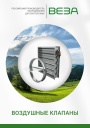
Каталог продукции Веза 2025 - Воздушные клапаны. pdf, 6.71 Mb
Каталог воздушных клапанов Веза: номенклатура, клапаны отсечные и регулирующие РЕГУЛЯР, РЕГУЛЯР-Л, РЕГЛАН, КЕДР и другие — конструкция, исполнения, приводы, технические характеристики, габаритные размеры. -
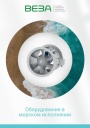
Каталог продукции Веза 2026 - Оборудование в морском исполнении. pdf, 7.62 Mb
Каталог вентиляционного и холодильного оборудования Веза в морском исполнении: радиальные и осевые вентиляторы, кондиционеры КОМПАС-БОВ, компрессорно-конденсаторные агрегаты КОМПАС-ККБ, шкафы управления КОМПАС-ШСАУ — технические характеристики и размеры. -
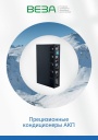
Каталог продукции Веза 2026 - Прецизионные кондиционеры АКП. pdf, 4.90 Mb
Каталог прецизионных кондиционеров АКП: назначение, исполнения, конструкция, технические характеристики, габаритные размеры, обозначение при заказе.
Новое в инструкциях
-
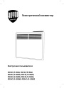
Электрические конвекторы Royal Thermo серии Capella RCHC/E. pdf, 5.01 Mb
Модели: RCHC/E-500, 502, 1000, 1002, 1500, 1502, 2000, 2002. Инструкция пользователя: устройство конвектора, управление прибором, уход и обслуживание, монтаж, хранение и транспортирование, технические характеристики, гарантийный талон. -

Бойлеры косвенного нагрева Royal Thermo. Правила установки. pdf, 251.55 Kb
Схема-памятка по установке бойлера косвенного нагрева: подключение к котлу и контурам ГВС/ХВС, группа безопасности, расширительный бак, диэлектрические муфты, фильтр очистки воды, заземление. -
Инверторные сплит-системы Shuft серии Asgard DC. pdf, 8.78 Mb
Модели: SFTHAI/IN-07HN8/BL, 09HN8/BL, 12HN8/BL, SFTHAI/OUT-07HN8/BL, 09HN8/BL, 12HN8/BL. Руководство по эксплуатации: монтажная схема и монтаж, описание пульта управления и режимов работы, Wi-Fi и мобильное приложение, уход и обслуживание, технические характеристики, устранение неисправностей, протоколы приёмки и тестового запуска, гарантийный талон.