

Инструкция на Горелки жидкотопливные серии NOE/NOF/NOG 18-100
Жидкотопливные горелки серии NOE/NOF/NOG 18-25 to 100-38. Инструкция по монтажу и эксплуатации.
Загружаем документ…
Текст инструкции
-
HANDBOOK Series NO automatic oil burners Models NOE/NOF/NOG 18-25 to 100-38 CAPACITY The Nu-way NOE/F/G 18-25 to NOE/F/G 100-38 pressure jet burners are designed for automatic High/Low/Off operation with burner outputs from 147-2940 kW (125,391-2,500,000 kcal/h; 501,56410,000,000 Btu/h. The burner…
-
Contents
Page 1. INTRODUCTION General Safety 2. BURNER Assembly Fitting to the Appliance Flue & Chimney Requirements Combustion Chamber Conditions Plant Room Ventilation 3. SITE SERVICES Electrical Power Supply Oil Supply Main Oil Storage Tank Oil Supply to the Burner Pumped Ring Main System Oil Temperature…
-
PRE-FIRING CHECK AND INITIAL SETTINGS Pre-commissioning Commissioning Pre-Heater Thermostat Settings Pre-Purge of Burner Fuel System Starting – Low Fire High Flame Operation Checking the Sequence Controller 6. ROUTINE MAINTENANCE Ignition Electrodes Air Diffuser Nozzles Photocell Cold Oil Filter Hot…
-
ILLUSTRATIONS
Page Electrical Data 4 Dimensions 4 Completely Assembled Package Fig 1. 5 Connecting HT Leads Fig 2. 6 Cartridge Heater and Thermostat Connections Fig 3. 6 Connecting Self-Sealing Quick Release Couplings Fig 4. 6 Fuel Connections to Burner Unit Fig 5. 6 Oil System Diagrams NOE Burners Fig 6a. 7 Oil…
-
DIMENSIONS
These dimensions are intended for general assessment of the overall sizes of the burners and should not be used without reference to our Technical Department or inclusion in drawings for installation purposes. Certified dimensional drawings are available on request on receipt of orders. BURNER MODEL…
-
INTRODUCTION The manual covers three types of burner:Models NOE 18-25 to 100-38 High/Low Burners (Class E Fuel) Models NOF 18-25 to 100-38 High/Low Burners (Class F Fuel) Models NOG 18-25 to 100-38 High/Low Burners(Class G Fuel) Where an instruction or information is applicable to only one of the…
-
BURNER Assembly – Mode Two At this stage it may be more convenient to fit the hinged extensions / flame tube assembly to the appliance before attaching the burner body. Ensure the gasket provided is fitted between the appliance and mounting flange. Alternatively the hinged extension may be attached…
-
FITTING TO THE APPLIANCE
If the burner is to be fitted to a new packaged unit with over-pressure conditions, refer to the Manufacturer’s recommendations. If the burner is to be used with an existing appliance, the chimney, flues, passage-ways and heat transfer surfaces must be cleaned. Prepare burner mounting plate (see…
-
OIL SYSTEM DIAGRAM NOF BURNER – FIG. 6B
A4-2483 OIL SYSTEM DIAGRAM NOG BURNER - FIG 6C A4-2482 Page 8
-
ELECTRICAL POWER SUPPLY
Connect the appropriate electricity supply to the burner observing all applicable Codes and Standards. Refer to specific burner wiring diagrams that are supplied with the burner or the appliance manufacturer’s handbook. Connect external auxiliary control circuits by reference to the appropriate…
-
PUMPED RING MAIN SYSTEM
An oil ring main system is essential for reliable burner operation. Multiple burner installations require careful flow balancing to ensure oil flow in all sections of the oil system. The ring main pumps and pipe size must be designed to give 1.33 times the total full swept volume of the burner…
-
BURNER OIL ATOMISING SYSTEMS The system of pressure atomisation is used throughout the range. The method of operation is the well-proven two-stage (high/low) constant pressure twin nozzle system. Each nozzle is controlled by a pressure operated cut-off valve integral with the nozzle block assembly.…
-
Model NOG for Class G fuel is based on the principle outlined except the air control device
is operated by an electric servomotor with an inlet fully closing air damper which closes the air supply during the burner “off” periods. 4-Pipe System - NOF (Hydraulic Air control) Burners NOG (Electric Air control) Burners MODELS NOE & NOF WITH HYDRAULICALLY OPERATED AIR DAMPER Air Control Damper…
-
FOR
NOE & NOF MODEL ONLY FIG. 10 Air Diffuser The air diffuser is fitted to the front end of the inner assembly of the burner and located within the flame tube attached to the hinged extension. The function of the air diffuser is to control the volume of combustion air and create a pressure drop over…
-
Primary Air Tube - Fig. 11
Forms part of the burner inner assembly. Its function is to regulate the volume of primary combustion air passing through the centre of the air diffuser and over the oil nozzles. The regulating holes may be fully exposed or partially restricted depending on the burner firing rate and characteristics…
-
Cams are ‘factory set’ as per WA4-7389. Cams Nos.2 to 5 will require adjusting when
burner is installed on its appliance, to cater for the particular nozzle size, resistance, etc. Re-check Cam No.1 for fully closing. The sequence provides for a ‘closed’ air damper position when the burner is in the ‘off’ position. This prevents cold air being drawn through the boiler and taking…
-
Title
CONNECTIONS FOR BERGER-LAHR MOTORS Drawing No. WA4-6996/2 Instructions for ‘Factory Setting’ of Berger Motor or Fitting of Replacement Motor Before motor is fitted to burner, cams to be set approximately as shown on WA4-7389. To Set Remove motor cover – rotate motor shaft (with special lever fitted)…
-
A
B BURNER OIL COMPONENTS Inner Assembly – Fig.11 The inner oil assembly is located in the hinged extension/flame tube of the burner. Its primary function is to carry preheated oil from the manifold block tot he atomising nozzles. Nozzle Block – Fig. 11 The multiple nozzle block isolated at the…
-
Oil Nozzles
The oil nozzles are fitted into the forward end of the nozzle block. The function is to spray oil into the combustion chamber at atomising temperature and pressure and in a volume commensurate with the capacity of the appliance to which the burner is fitted. IMPORTANT NOTE: When fitting nozzles to…
-
Magnetic Valve (Three-Way)
Its function is to control the supply of oil to the hydraulic/spring-loaded nozzle piston cut-off assembly and hydraulic ram mechanism operating the air control unit during the change to low fire. On the change from high to low fire the three-way magnetic valve exhausts oil to the return side of the…
-
CONTROL PANEL
Is mounted on the left-hand side of the burner viewed from the rear. It includes the Sequence Controller, Ignition Transformer, Motor and Preheater Contactors, Low Flame/Auto Hand Switch, On/Off Switch, Lights and Terminal connections. A separate auxiliary panel for steam boilers (AOTC) requirements…
-
PREHEATER THERMOSTAT SETTINGS
FUEL Low Limit Control High Limit °C °F °C °F °C °F Class E - 8 cSt at 100°C Class F - 20 cSt at 100°C Class G - 40 cSt at 100°C PRE-PURGE OF BURNER FUEL SYSTEM – Fig. 8/9 The burner fuel system is designed to prevent cold oil in the burner pipework passing through the nozzles during the starting…
-
STARTING - LOW FIRE (ONE STAGE)
At the end of the predetermined purge period the on/off magnetic oil valve will be energised and close thus preventing the return of oil to the suction side of the pump. Simultaneously the hydraulic lines to the ram operating the air control and the high fire nozzle cut-off assembly will be…
-
Check that the atomising oil pressure is in accordance with the figures given above
Inspect the flame through the inspection window provided. It should be clear with a steady bright light visible through the slots in the air diffuser and a continuous halo is visible around the outer edge of it. With the burner now working on high fire, a check may be carried out to establish…
-
ROUTINE MAINTENANCE When carrying out routine maintenance always turn off the power supply to the burner. Regularly clean the fan blades with a stiff brush. Access is through the top cover secured by 4 screws. Frequently inspect the air inlet to the burner and ensure there are no obstructions to air…
-
PHOTOCELL
Clean the photo electric cell lens with a dry, clean cloth. COLD OIL FILTER Rotate the cleaning knob daily. The plug in the sump should be removed approximately every month/four weeks to drain off any sludge or water that may have accumulated there. HOT OIL FILTER – Located in Oil Preheater Remove…
-
BURNER STARTS, FAILS TO RUN
SYMPTOM Burner starts, Fails to run. POSSIBLE REASON Partially choked nozzle. Soot/carbon on diffuser. Low oil temperature. Too much air. Dirty photocell lens Wrongly positioned photocell. Oil shortage. Faulty wiring. REMEDY Clean or replace Clean Check thermostat settings Adjust air control Clean…
-
MODELS
NOE NOF NOG FUEL The three models of heavy oil burners are suitable for use on residual fuels with viscosities as specified below. Model NOE Class E: 8 cSt at 100°C Model NOF Class F: 20 cSt at 100°C Model NOG Class G: 40 cSt at 100°C Ring main system Residual fuel Class E, F & G NOTE: All burners…
Схемы, таблицы и рисунки — в просмотре документа выше. Клик по номеру страницы открывает её в просмотре.
Новое в каталогах
-
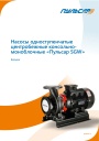
Каталог продукции Пульсар - Насосы одноступенчатые центробежные консольно-моноблочные «Пульсар SGW». pdf, 8.68 Mb
Каталог продукции Пульсар - Насосы одноступенчатые центробежные консольно-моноблочные «Пульсар SGW» -
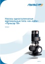
Каталог продукции Пульсар - Насосы одноступенчатые вертикальные типа «ин-лайн» «Пульсар TB». pdf, 7.95 Mb
Каталог продукции Пульсар - Насосы одноступенчатые вертикальные типа «ин-лайн» «Пульсар TB» -

Каталог энергоэффективного оборудования для котельной Huch EnTEC 2026 . pdf, 39.59 Mb
Каталог энергоэффективного оборудования для котельной Huch EnTEC 2026
Новое в инструкциях
-
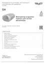
Вентиляторы в круглом корпусе Shuft серии SH. pdf, 646.47 Kb
Модели: SH 160, 200, 250, 315, 400. Руководство по установке, эксплуатации и техническому обслуживанию: технические характеристики, размеры, монтаж, электрические подключения, ввод в эксплуатацию, обслуживание и чистка, устранение неисправностей. -
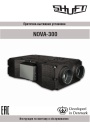
Приточно-вытяжные установки Shuft серии NOVA. pdf, 4.29 Mb
Модель NOVA-300. Инструкция по монтажу и обслуживанию: принципиальная схема установки, массогабаритные показатели, монтаж воздуховодов и дренажа, подключение электропитания, схема электрических соединений, пусконаладка, обслуживание, неисправности, подключение к системе диспетчеризации. -
Компактные приточно-вытяжные установки Shuft серии UniMAX-P CE-A. pdf, 8.10 Mb
Модели: UniMAX-P 450 CE-A, 800 CE-A, 1000 CE-A, 1500 CE-A. Руководство по монтажу и эксплуатации подвесных установок с пластинчатым рекуператором и электронагревателем: характеристики, монтаж, схемы подключений, пусконаладка, пульт управления, техническое обслуживание, неисправности.