

Инструкция на Микропроцессорный контроллер Emicon EMIplus
Микропроцессорный контроллер EMIplus для прецизионных кондиционеров Emicon: функции системы, интерфейс оператора, плата контроллера, настройка и изменение параметров, аварийные сигналы. Руководство по эксплуатации и обслуживанию. Документ на английском языке.
Загружаем документ…
Текст инструкции
-
CONDIT. HUMIDIF. OPT. Code EPSTDECZUA Ver. 1.002 - 04/06/98 MICROPROCESSOR EMIplus
-
Rev. 0 dtd 04/’02
CONTENTS 1 1.1 1.2 GENERAL FEATURES Functions carried out by the system Hardware being utilised Page 2 Page 2 Page 2 2.1 2.2 2.3 2.4 EMIPLUS OPERATOR INTERFACE The display The keypad The led The EMIplus board Page 2 Page 2 Page 3 Page 5 Page 5 3.1 PARAMETERS CONFIGURATION AND MODIFICATION Parameters…
-
Rev. 0 dtd 04/’02
1 - GENERAL FEATURES EMIplus is an electronic controller system which provides advanced microprocessor management of air-treatment and air-conditioning units. 1.1 Functions carried out by the system ! Temperature and relative humidity regulation. ! Control and signalling of the status of all the…
-
Rev. 0 dtd 04/’02
2.2 The keypad The EMIplus is equipped with a 15-button keypad that along with the display represents the interface between the operator and the system. The keypad allows the selection and configuration of the set-point limits, alarm thresholds, intervention delays of the alarms etc. It allows also…
-
Rev. 0 dtd 04/’02
MENU button Go to the MAIN_MASK window. INFO button Go to the M_VERSION window. MANUT button Go to the M_VIS_TIMER1 window. PRINT button Usable in the version with printer. I/O button Go to the M_SYNOPTIC1 window. CLOCK button Go to the M_REG_CLOCK window. SET button Go to the M_CALC_SETP window.…
-
Rev. 0 dtd 04/’02
2.3 The led At the side of each button a green LED is found which lights up when the associated button is being pressed and indicates in which group of masks the user is situated. Three other LED are placed under the rubber buttons and indicate respectively: ON / OFF button green LED indicates that…
-
Rev. 0 dtd 04/’02
1) Power supply connector 24 Vac 50/60 Hz 15 VA or 24 Vdc, 10 W. 2) EMIplus LAN connector. 3) Telephone-type connector for connection to the User terminal unit (MMI, Man Machine Interface) or to local network. 4) Yellow LED indicating the mains power present. 5) `250 Vac, 2 A slow-blow fuse (2TA).…
-
Rev. 0 dtd 04/’02
Table 1 - Input and output I/O Digital Inputs REFERENCE ID1 - IDCM1 ID2 - IDCM1 ID3 - IDCM1 ID4 - IDCM1 ID5 - IDCM1 ID6 - IDCM2 ID7 - IDCM2 ID8 - IDCM2 ID9 - IDCM2 ID10 - IDCM2 ID11 - ID11R ID12 - ID12R DIGITAL INPUT COMPRESSOR 1 GENERAL ALARM (HIGH PRESSURE OR THERMAL) COMPRESSOR 2 GENERAL ALARM…
-
Rev. 0 dtd 04/’02
3 - PARAMETERS CONFIGURATION AND MODIFICATION The parameters are divided into four levels: A USER part, not protected by password, which allows monitoring the quantities being regulated, selecting the set-point of principal control, displaying the active alarms and the stored alarms. A USER part…
-
Rev. 0 dtd 04/’02
3.1 Parameters configuration The first 10 buttons of the keypad allow the user to carry out every type of operation, ranging from configuration to simple check of the parameters. The blue and red buttons are not employed. Their function is to select the desired loop (or the chain of masks). The 5…
-
Rev. 0 dtd 04/’02
MENU BUTTON This button allows the display of the values detected from the selected probes (the temperature probe is the only one always present and not selectable). The operation is: - press the MENU button once. Result of the operation: - the display shows the mask indicating temperature, room…
-
Rev. 0 dtd 04/’02
INPUT / OUTPUT BUTTON This button displays the interface card inputs and outputs status. The operation is: -press the Input/Output button once. Result of the operation: - the display shows the status of all digital inputs. The operation is: - press the Increase/Decrease button Result of the…
-
Rev. 0 dtd 04/’02
SET BUTTON This button allows the configuration of the set-points for room temperature and room humidity regulation. The operation is: -press the Set button once. Result of the operation: -the display shows the mask for the temperature set-point selection. The operation is: -press the…
-
Rev. 0 dtd 04/’02
MANUAL BUTTONS These buttons pressed together for few seconds enable to enter the manual activation of the devices loop. The operation is: - press the Menu and Set buttons together for few seconds. Result of the operation: - the display shows a mask asking to proceed or not with the manual…
-
Rev. 0 dtd 04/’02
INCREASE / DECREASE BUTTON This button allows to move among the masks which make up the loop. If employed after having pressed the Enter button, it enables to set the parameters values. 1) If a loop is made up of masks 1, 2, 3, 4 and 5 and mask 1 is displayed, by pressing more times the Increase…
-
Rev. 0 dtd 04/’02
M_MAINT_PASS Enter maintenance password: 0000 Right password! M_SEL_TIMER1 Main fan hour meter: Threshold: Req.reset: Pre-setting of the fan time operating time established before the maintenance. 000x1000 N 000000 M_SEL_TIMER2 Compressor 1 hour meter: Threshold: 000x1000 Req.reset: N 000000…
-
Rev. 0 dtd 04/’02
M_MANUAL4 Manual activation of the devices. Manual procedure: Unloader 1 Unloader 2 N N M_MANUAL5 Manual procedure: Manual activation of the devices. Open heat.fl.v. N Close heat.fl.v. N M_MANUAL6 Manual procedure: Manual activation of the devices. Cool. valve N 00.0V Heat. valve N 00.0V…
-
Rev. 0 dtd 04/’02
M_SYNOPTIC5 Digital outputs C= close O= open 01:OOO 04:OOO 07:OOO 10:OO Displays the state of the analog inputs and outputs. It is displayed with the I/O button. M_SYNOPTIC6 Humidifier Main switch OFF Fill valve OFF Drain valve OFF Displays the state of the analog inputs and outputs. It is displayed…
-
Rev. 0 dtd 04/’02
M_DAILY2_TEMP Temperature Daily time zone 2 Start time 00:00 Set-point 00.0°C Pre-setting of the time band no. 2. The time band starting hour and the relevant temperature set-point will be selected. The time band ending will be the beginning of the following one. M_DAILY3_TEMP Temperature Daily time…
-
Rev. 0 dtd 04/’02
M_SELECT_SETP Set-points Temperature Humidity 00.0°C 000.0% Change of the set-points. The values must be included within the limits being preset in the M_PARAM-USERx masks. PROG BUTTON - M_SERV_PASS Enter the service password 0000 Right password! M_PARAM_USER1 Temperature setpoint limits Minimum…
-
Rev. 0 dtd 04/’02
M_PARAM_USER8 Compensation: Setpoint 00.0°C Band 00.0°C Offset 00.0°C Parameters for the compensation. M_PARAM_USER9 Room temperature alarms: Offset low 00.0°C Offset high 00.0°C Values that limit the temperature range. Value to be subtracted from the temperature set-point. Value to be added to the…
-
Rev. 0 dtd 04/’02
M_MANUF_CONF2 Supply air temper. probe enabled N Outlet water temper. probe enabled N The devices present in the machine are enabled. M_MANUF_CONF3 External air temper. probe enabled N Inlet water temper. probe enabled N The devices present in the machine are enabled. M_MANUF_CONF4 Room humidity…
-
Rev. 0 dtd 04/’02
M_MANUF_PARAM4 Step compressor 1 without energy sav. Position 000.0% Hysteresis 000.0% Positioin of the steps with respect to the proportional band. To better understand the function go to the paragraph “Concept of step”, see “regulation graphs”. M_MANUF_PARAM5 Step compressor 2 without energy sav.…
-
Rev. 0 dtd 04/’02
M_MANUF_PARAM13 Presetting of the step relevant to the resistance heating. See paragraph “Concept of step”. Step heater 2 Position Hysteresis 000.0% 000.0% M_MANUF_PARAM14 Step heater binary control Position 000.0% Hysteresis 000.0% Presetting of the step relevant to the resistance heating. See…
-
Rev. 0 dtd 04/’02
M_MANUF_PARAM22 High temperature limit (stop dehum.) Position 000.0% Hysteresis 000.0% Dehumidification stop step. See “Humidity control graphs”. M_MANUF_PARAM23 Nomin. prod. 00 kg/h Voltage 000 V Phase number 1 TAM model 050 Parameters for the identification of humidifier type. M_MANUF_PARAM24…
-
Rev. 0 dtd 04/’02
M_MANUF_TIME4 Air flow alarm delay time 0000 sec Air flow controller acquisition delay. M_MANUF_TIME5 Minimum compressor off time 0000 sec Minimum compressor on time 0000 sec Compressor timing. M_MANUF_TIME6 Delay between starts same comp. 0000 sec Delay between starts diff. comp. 0000 sec…
-
Rev. 0 dtd 04/’02
5 - ALARMS The alarm state is shown in all masks where “AL” is found on the upper right corner of the display and enables to see all masks containing news in relation to the occurred fault. Every state of alarm is signalled: - acoustically by the buzzer incorporated into the EMIplus relay card…
-
Rev. 0 dtd 04/’02
AL_8 AL08 00:00 00/00/00 Heater 2 Overload AL_9 AL09 00:00 00/00/00 Fire or Smoke Alarm (serious alarm) UNIT OFF AL_10 AL10 00:00 00/00/00 Air Filter Alarm AL_11 AL11 00:00 00/00/00 High Room Temperature Alarm AL_12 AL12 00:00 00/00/00 Low Room Temperature Alarm AL_13 AL13 00:00 00/00/00 High Room…
-
AL_18
AL18 00:00 00/00/00 Compressor 2 Operation Hours Alarm The operating threshold preset in the maintenance branch has been exceeded. AL_19 AL19 00:00 00/00/00 Main Fan Operation Hours Alarm AL_20 AL20 00:00 00/00/00 Room Temperature Probe Faulty or not Connected AL_21 AL21 00:00 00/00/00 Outlet Water…
-
Rev. 0 dtd 04/’02
-
Rev. 0 dtd 04/’02
6 - LIST OF THE PROGRAMMABLE SETS Following table shows the factory configured value (value column) for all different parameters. Factory values being taken as machine parameters whenever initialising the unit (M_MANUF_MENU, M_DEFAULT mask), are shown in the PRE-SET column. SELECTABLE QUANTITIES…
-
SELECTABLE QUANTITIES
Compensation offset Temperature alarm low offset high offset Humidity alarm low offset high offset Outlet water temperature threshold alarm low offset high offset Print repetition Temperature set-point automatic variation Temperature time band (1-4) Start time Set-point Humidity time band (1-4)…
-
SELECTABLE QUANTITIES
Start End Warm modulating valve Start End Colt 3 point valve Start End Warm 3 point valve Start End Humidification step Position Hysteresis Dehumidification step Position Hysteresis Low temp. limit (stop dehumidification) Position Hysteresis High temp. Limit (stop dehumidification) Position…
-
Rev. 0 dtd 04/’02
7 - NETWORK CONNECTION Every pLAN device must be addressed to be identified by the other ones. In case two or more devices have the same identifying address the network cannot work. Since the terminals and the boards have the same type of address, it cannot exit the same identifying address assigned…
-
Rev. 0 dtd 04/’02
7.2 Terminals address selection Terminal board rear side view. Picture 6 MICROPROCESSOR ON Dipswitch Printer connector OFF pLAN connector Terminal address is programmed by means of the dip-switches set on the Terminal board rear side. Terminal address is selectable in the 1-16 range using the 1-5…
-
Rev. 0 dtd 04/’02
7.3 Terminals management ! A maximum number of three (3) terminals can be software-driven by only one EMIplus board linked to the network. The messages appear on the display simultaneously and not independently; just like keyboards and displays in parallel connexion. ! Every terminal linked to a…
-
Rev. 0 dtd 04/’02
7.4 pLAN configuration procedure ! At start up of a pLAN network or at I/O board replacement the first operation to carry out is to activate the procedure for terminals configuration. ! Before beginning this procedure make sure that to every I/O board and to every terminal have been assigned their…
-
Rev. 0 dtd 04/’02
STAGE 2: Selection of Terminals associated The masks displayed are: Terminal Config Press ENTER to continue Enter ß P:01 Adr Priv/Shared Trm1 09 Pr Trm2 none -Trm3 16 Sh Ok? No ! Enter key allows to move the cursor among the mask fields, while the keys allow to change the current value of the field.…
-
Rev. 0 dtd 04/’02
7.6 Network status display: NetSTAT ! The program is provided with a procedure that allows to display in real time the status of the currently connected peripheral devices. ! Such procedure is activated by the simultaneous pressure of buttons 0-1-2 (Increase Decrease - Enter) for at least 10 seconds…
-
Rev. 0 dtd 04/’02
8 - STAND-BY The connection of the EMIplus boards in a pLAN local network allows them to communicate with one another and exchange variables. The main function of this exchange of variables is to allow all the units to be controlled by one single EMIplus terminal. In addition, it allows the units to…
-
Rev. 0 dtd 04/’02
The following parameters manage the rotation of the units and are present only in the screen of unit number 1. They are listed and described below. ! screen M_MANUF_PARAM25 (manuf. branch). Number Units: indicates the total number of units involved in the scheduled rotation (the number set must also…
-
Rev. 0 dtd 04/’02
9 - DATA BASE OF THE SUPERVISOR The variables listed below will be transmitted between EMIplus and supervisor only, if all following conditions will be met: ! ! ! ! the serial card is inserted into the proper connector that is found on the interface; the supervisory function is enabled in the…
-
Address
MICROPROCESSOR EMIplus Description Air supply temperature probe failure alarm Outlet water temperature probe failure alarm External air temperature probe disconnection alarm Humidity probe failure alarm EPROM failure alarm Temperature regulation type Humidity probe enabling Outlet water probe…
-
Rev. 0 dtd 04/’02
9.2 Whole variables Address Description Cold 0/10V valve ramp start Cold 0/10V valve ramp end Warm 0/10V valve ramp start Warm 0/10V valve ramp end Compressor 1 step without energy saving Compressor 1 hysteresis without energy saving Compressor 2 step without energy saving Compressor 2 hysteresis…
-
Rev. 0 dtd 04/’02
9.3 Analog variables Address Description Ambient temperature Ambient humidity Outlet water temperature External air temperature Supply air temperature Dead zone in temperature Ambient humidity band Ambient humidity set Low temperature alarm offset High temperature alarm offset Low humidity alarm…
Схемы, таблицы и рисунки — в просмотре документа выше. Клик по номеру страницы открывает её в просмотре.
Новое в каталогах
-
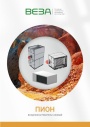
Каталог продукции Веза 2026 - Воздухонагреватели газовые ПИОН. pdf, 6.55 Mb
Каталог газовых воздухонагревателей ПИОН: назначение, конструкция и исполнения, технические характеристики, габаритные размеры, обозначение при заказе. -
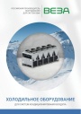
Каталог продукции Веза 2026 - Холодильное оборудование для систем кондиционирования воздуха. pdf, 4.97 Mb
Каталог холодильного оборудования Веза для систем кондиционирования: чиллеры, компрессорно-конденсаторные блоки, фанкойлы и другое оборудование — технические характеристики, габаритные размеры, обозначение при заказе. -
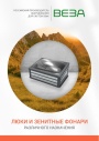
Каталог продукции Веза 2025 - Люки и зенитные фонари различного назначения. pdf, 8.45 Mb
Каталог люков дымоудаления и зенитных фонарей Веза различного назначения: конструкция и исполнения, приводы и автоматика, технические характеристики, габаритные размеры.
Новое в инструкциях
-

Мульти-сплит-системы Shuft серии FMI. pdf, 4.82 Mb
Модели: внутренние блоки SFMS/I-07…18 HB FMI/N8/IN/WHITE, наружные SFMO/I-14…42 FMI-2…5/N8/OUT. Руководство по эксплуатации: технические характеристики, управление кондиционером, монтаж, техническое обслуживание, поиск и устранение неисправностей, возможная комплектация блоков, гарантийный талон. -
Воздушные клапаны Shuft серии DCGAr. pdf, 4.57 Mb
Паспорт (объединённый эксплуатационный документ) круглых воздушных клапанов DCGAr: назначение, описание, комплектация, характеристики, размеры и вес, монтаж и эксплуатация, обслуживание, гарантия. -
Осушители воздуха Shuft серии SBW. pdf, 1.08 Mb
Модель SBW 150A. Руководство по установке и эксплуатации настенного осушителя: принцип работы, параметры моделей, размеры, проводной контроллер и пульт ДУ, схема подключения платы, монтаж, обслуживание, коды ошибок.