

Инструкция на Микропроцессорный контроллер Emicon EMIpro
Микропроцессорный контроллер EMIpro для прецизионных кондиционеров Emicon: интерфейс пользователя, индикация, плата входов/выходов, параметры, часы и расписание, аварийные сигналы. Руководство по эксплуатации и обслуживанию. Документ на английском языке.
Загружаем документ…
Текст инструкции
-
line
alarm on on/off Prg Sel alarm enter Clear EMIpro MICROPROCESSOR
-
Rev. 0 dtd 02/’02
CONTENTS 1.1 GENERAL CHARACTERISTICS General description Page 2 Page 2 2.1 2.2 2.3 2.4 2.5 EMIPRO USER INTERFACE The display Operating indicators The keypad I/O Card (input/output) Meaning of the inputs and outputs Page 2 Page 2 Page 4 Page 4 Page 5 Page PROGRAMMING PARAMETERS AND THEIR MODIFICATION…
-
Rev. 0 dtd 02/’02
1 - GENERAL CHARACTERISTICS 1.1 General description The EMIpro is an electronic control for the complete management of precision air-conditioners, both in direct expansion versions (with 1 or 2 compressors), with 1 or 2 heating elements or with batteries (valve on the heating battery and/or valve on…
-
Rev. 0 dtd 02/’02
8.8:8.8 Ambient temperature, when programming it displays the value of the parameters °C - °F Temperature unit of measure: degrees Centigrade/Fahrenheit. Ambient humidity, when programming it displays the no. of the parameters 88 % H Relative humidity unit of measure. Buzzer active. Hour counter…
-
Rev. 0 dtd 02/’02
2.2 Operating indicators The main states of the regulator are displayed to the user through 3 Led on the front panel (Picture 3). line alarm on Picture 3 led LINE (yellow): led ALARM (red): led ON (green): control powered; machine alarm (the siren symbol on the display is on only when the buzzer is…
-
Rev. 0 dtd 02/’02
2.4 I/O Card (Input/Output) Picture 5 depicts the I/O Card. The I/O Card shows following components: - Molex connectors (1 - 2 - 3), for carry out the main connections; - male connector (4),for unloading or copying data; - prearranged housing (5)for the clock board memory (optional); - prearranged…
-
Rev. 0 dtd 02/’02
Table 1 - I/O Inputs and outputs Digital inputs - Connector 2 ID6 ID7 ID8 ID9 UV On/Off remote (HE=1) Flow gauge Filter dirty Heating elements safety External alarm/input for rotation of more units (Pb, H2, HA) Humidifier alarm (H8=1) Water flow alarm(PF=1) UV warm/cold On/Off remote (HE=1) Flow…
-
Rev. 0 dtd 02/’02
3 - PROGRAMMING PARAMETERS AND THEIR MODIFICATION 3.1 Parameters The parameters are divided into 3 levels, each of them contains the previous, which the user can access to customise the operation of the EMIpro. Livel Access DIRECT (D) Immediate access USER (U) Access with Service Center password…
-
Rev. 0 dtd 02/’02
enter Once having entered any level of parameters, one pressing of the Parameter selected, while the and button displays the value, flashing, of the buttons can be used to modify such value. Picture 8 on/off Prg Sel alarm enter 1 1 Clear Press again Then, using the enter to confirm the new value.…
-
таблицы и схемы — в просмотре
-
Rev. 0 dtd 02/’02
-
c Compressor
Type Min Rev. 0 dtd 02/’02 Max U.o.M. Default 1 Minimum ON time 2 Minimum OFF time 3 Time between 2 start-ups U 0 300 s 60 U U s s ON delay between the 2 compressors 5 OFF delay between the 2 compressors U 0 300 s 30 U 0 300 s 0 F 0 1 flag 0 U 0 300 s 20 U 0 30000 h 0 6 Compressor rotation 0 =…
-
Rev. 0 dtd 02/’02
P Alarm Type Min Max U.o.M. Default 1 Flow alarm delay from fan start-up U 0 250 s 20 2 Flow alarm delay during operation U 0 90 s 5 3 Low pressure alarm delay from compressor ON U 0 250 s 40 4 Buzzer activation 0 = OFF, 1-14= min. 15= continuous U 0 15 min 0 5 Reset alarms (various configurations)…
-
H
EMIpro MICROPROCESSOR General Rev. 0 dtd 02/’02 Type Min Max U.o.M. Default 5 Operating mode of the 2 “cool” outputs 1 = 1 compressor 2 = compressors on 2 circuits 3 = three-point valve 4 = 2 compressors in binary parallel 5 = 2 compressors in tandem (50+50%) F 1 5 flag 1 6 Operating mode of the 2…
-
H
EMIpro MICROPROCESSOR General Rev. 0 dtd 02/’02 Type Min Max U.o.M. Default d Function of probe B3 0 = humidity control 1 = condensation control F 0 1 flag 0 E ON/OFF digital input 0 = absent 1 = present U 0 1 flag 0 F Alarm relay logic 0 = de-energised in alarm for all alarms 1 = energised in alarm…
-
Rev. 0 dtd 02/’02
5.2 Time bands Entering the parameter rt (see USER parameter modification) allows the selection of rt= 1 or 2, enabling the time band enter function. Pressing the button displays, in sequence, with the scrolling of a segment, time bands 1, 2, 3, 4 of day 1 on/off (Monday), , time bands 1, 2, 3, 4 of…
-
Rev. 0 dtd 02/’02
The display includes an incremental index in the right-hand field, which identifies the current position; the hundreds then appear in the field on the left (e.g.: “1 rES 55” indicates that a reset of the machine was performed, and the position is 155). 1 es 55 Picture 12 5.3.2 Alarm log exit alarm…
-
Rev. 0 dtd 02/’02
8 - ALARMS AND SIGNALS In the event of an alarm, the machine performs the following actions: > > > activates the buzzer and display , (if enabled and machine ON); activates the alarm relay (according to parameters HF, HA); displays the alarm code and switches on the corresponding red Led. alarm In…
-
8.1 Table of alarm
n. Code E1 E2 E3 E4 Er: E EE EL Description probe B1 probe B2 probe B3 probe B4 Eeprom boot Eeprom run insufficient power 8 9 H1 H2 high pressure C1 high pressure C2 10 L1 low pressure C1 11 L2 low pressure C2 12 F1 filter dirty FL FA CF r1 flow smoke - fire water flow heating elements 17 At supply…
-
Rev. 0 dtd 02/’02
8.2 Alarm signals and description All the alarms, except for the generic external alarm (AL), configured by parameter Pb, and the clock, are detected only when the machine is On. E1: ambient temperature probe(B1) failure: generated due to open or short-circuited probe. Alarm delayed by 1 minute from…
-
Rev. 0 dtd 02/’02
F1: dirty filter Signal-only alarm. No outputs are deactivated. FL: air flow alarm Alarm delayed by parameters P1 and P2. The activation of this alarm causes the switching off of all of devices without waiting the delay times of the compressors and the fan. If set for automatic reset, parameter P5…
-
Rev. 0 dtd 02/’02
tC: compressor thermal overload alarm Immediate alarm, causes the instant switching off of the compressor. This is managed only if parameter H5= 1 or 5 (one compressor only or two compressors in tandem). tF: fan thermal overload alarm Immediate alarm, causes the instant switching off of all devices…
Схемы, таблицы и рисунки — в просмотре документа выше. Клик по номеру страницы открывает её в просмотре.
Новое в каталогах
-

Каталог продукции Пульсар - Насосы одноступенчатые центробежные консольно-моноблочные «Пульсар SGW». pdf, 8.68 Mb
Каталог продукции Пульсар - Насосы одноступенчатые центробежные консольно-моноблочные «Пульсар SGW» -

Каталог продукции Пульсар - Насосы одноступенчатые вертикальные типа «ин-лайн» «Пульсар TB». pdf, 7.95 Mb
Каталог продукции Пульсар - Насосы одноступенчатые вертикальные типа «ин-лайн» «Пульсар TB» -

Каталог энергоэффективного оборудования для котельной Huch EnTEC 2026 . pdf, 39.59 Mb
Каталог энергоэффективного оборудования для котельной Huch EnTEC 2026
Новое в инструкциях
-
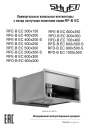
Прямоугольные канальные вентиляторы Shuft серии RF-B EC. pdf, 7.50 Mb
Модели: RFE-B EC 300x150 … 600x350, RFD-B EC 600x300 … 1000x500. Паспорт (объединённый эксплуатационный документ): описание, массогабаритные показатели, монтаж, подключение электропитания, схема электрического соединения, пуск, обслуживание, неисправности, гарантийные обязательства, технические данные. -
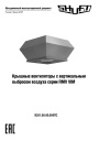
Крышные вентиляторы Shuft серии RMV VIM. pdf, 4.41 Mb
Модели: RMVE 190/300-2 … 450/670-4, RMVD 311/440-4 … 630/950-4 VIM. Паспорт (объединённый эксплуатационный документ): описание, массогабаритные показатели, монтаж, схемы электрических соединений, пуск, обслуживание, гарантийные обязательства, технические данные. -
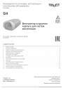
Вентиляторы в круглом корпусе Shuft серии SH. pdf, 646.47 Kb
Модели: SH 160, 200, 250, 315, 400. Руководство по установке, эксплуатации и техническому обслуживанию: технические характеристики, размеры, монтаж, электрические подключения, ввод в эксплуатацию, обслуживание и чистка, устранение неисправностей.