

Инструкция на Тормозные модули ZIEHL-ABEGG Acontrol серии ZAdyn4C
Тормозные модули ZIEHL-ABEGG Acontrol серии ZAdyn4C. Руководство по эксплуатации.
Загружаем документ…
Текст инструкции
-
Brake activation for ZAdyn4C
Original operating instructions Store for future use ! R-TBA13_01-GB 1630 Art.-Nr. 00163414-GB
-
Content
1 General information . . . . . . . . . . . . . . . . . . . . . . . . . . . . . . . . . . . . . . . 1.1 Structure of the operating instructions . . . . . . . . . . . . . . . . . . . . 1.2 Target group . . . . . . . . . . . . . . . . . . . . . . . . . . . . . . . . . . . . . . . . 1.3 Exclusion of…
-
5.7 5.8 Connection ZAdyn4C . . . . . . . . . . . . . . . . . . . . . . . . . . . . . . . . . 19 5.6.1 5.6.2 19 19 Activation of the brake contactor K3. . . . . . . . . . . . . . . . . . Triggering operation without contactors . . . . . . . . . . . . . . . Connection control system . . . . . . . . .…
-
General information
1 General information 1.1 Structure of the operating instructions These Operating Instructions serve for safe working on and with the Brake Module for the ZAdyn4C. It contains safety instructions that must be complied with as well as information that is required for failure-free operation of the…
-
Safety instructions
2 Safety instructions 2.1 General This chapter contains instructions to prevent personal injury and property damage. These instructions do not lay claim to completeness. In case of questions and problems, please consult our company technicians. 2.2 Intended use The Brake Module is an external…
-
Safety instructions
2.4 Product safety The device conforms to the state of the art at the time of delivery and is fundamentally considered to be reliable. The device and its accessories must only be used in a flawless condition and installed and operated with compliance to the operating instructions. Exceeding the…
-
Safety instructions
2.7 Working on device/hazards through residual voltage Before working on previously installed devices, separate them from the mains and secure them against reconnection. Danger! Through use of capacitors in the ZAdyn4C danger of death exists even after switching off the ZAdyn4C through directly…
-
Product overview
• these staff receive regular instruction in all relevant occupational safety and environ• mental protection issues, are knowledgeable about the operating instructions and, especially, are familiar with the safety instructions contained therein. All safety and warning notices attached to the device…
-
Mechanical installation
4 Mechanical installation 4.1 General notes The Brake Module is mounted on the side of the ZAdyn4C Danger! The following points must be complied with during the mechanical installation to avoid causing a defect in the device due to assembly errors or environmental influences: Before installation •…
-
Mechanical installation
4.2 Assembly on the ZAdyn4C 011-032 " Push the mounting plate into the top groove of the ZAdyn4C top groove mounting plate " Screw the M5 screws with washers two turns into the mounting plate. " Fit the fastening plate in such a way that the M5 screws grips the recesses (3) in the fastening plate.…
-
Mechanical installation
" Tighten the M5 screws. " Hook the Brake Module into the top hooks on the fastening plate (6) with the openings at the side (7). Press the Brake Module down carefully until it is touching. top hook of the fastening plate openings of the Brake Module " Remove the cover of the Brake Module. " Tighten…
-
Mechanical installation
" Mount the cover of the Brake Module. 4.3 Assembly on the ZAdyn4C 040-074 " Insert the hook (1) of the fastening plate in the openings (2) on the right side of the ZAdyn4C. Ensure here that the chamfer (3) of the fastening plate is on the right side. The press-in nut (4) of the fastening plate…
-
Mechanical installation
" Hook the Brake Module into the top hooks on the fastening plate (7) with the openings at the side (8). Press the Brake Module down carefully until it is touching. top hook of the fastening plate openings of the Brake Module " Remove the cover of the Brake Module. " Tighten M4 screw. 9 9 M4 screw "…
-
Mechanical installation
4.4 Dimensions / minimum clearances 126.1 375 ZDSB01M0 77.5 429 Brake Module dimensions in mm 377.5 ZAdyn4C 011-032 and Brake Module dimensions in mm R-TBA13_01-GB 1630 ZAdyn4C 011-032 and Brake Module minimum distances in mm Part.-No. 00163414-GB 14/32
-
таблицы и схемы — в просмотре
-
Electrical installation
5 Electrical installation Danger! Never work on the Brake Module and the ZAdyn4C under voltage. The intermediate circuit of the ZAdyn4C ( terminals X4: +DC / X2:-DC ) is still under voltage even after switching off the ZAdyn4C. Wait at least 3 minutes before working on the device Danger! Operating…
-
Electrical installation
5.2 Terminal positions Terminal positions 1 X-BA activation of brakes 2 X-K1 monitoring of brake contactors 3 X-K2 Voltage supply brakes / Break test, emergency rescue 4 X-SC activation of STO relays safety circuit R-TBA13_01-GB 1630 Part.-No. 00163414-GB 17/32
-
Electrical installation
5.3 Strain relief " A cable tie must be attached to all lines for strain relief. Fix the cable ties to the recesses provided in the Brake Module housing (see fig.). 1 1 recesses for strain relief 5.4 Protective earth connection The protective earth is already pre-assembled on the Brake Module. "…
-
Electrical installation
5.5 Connection motor brake The maximum line length is 25 m. " Connect the motor brakes to the terminal X-BA. ZIEHL-ABEGG SE offers the pre-fabricated cable L-BA-...-HX-BM/SBM. 5.6 Connection ZAdyn4C 5.6.1 Activation of the brake contactor K3. The brake contactor K3 is activated by a relay-output of…
-
Electrical installation
5.7 Connection control system 5.7.1 Evaluation of the safety circuit The operation without contactors of the ZAdyn4C requires the evaluation of the safety circuit. The ralays K1 and K2 are activated depending on the safety circuit. " Connect the safety circuit to the terminal X-SC. ZIEHL-ABEGG SE…
-
Electrical installation
For further information about the brake release monitoring by the ZAdyn4C, see the ZAdyn4C Operating Instructions, chapter "Electrical Installation/Brakes". 5.9 Process BM Sicherheitskreis K1+K2 K4 K3 Z4 Eingänge STO_A STO_B Ausgänge MB K1, K2 STO relay K4 Brake contactor K3 Brake contactor STO_A…
-
Electrical installation
5.10 Circuit suggestions Brake Module and ZAdyn4C 5.10.1 Actuation for brakes without over excitation Power supply brakes Power supply contactor / Safety circuit Contactor control manual brake release A manual brake release B Emergency operation / two-circuit test Relay outputs R-TBA13_01-GB 1630…
-
Electrical installation
5.10.2 Actuation for brakes with over excitation Power supply brakes Power supply contactor / Safety circuit Contactor control manual brake release A manual brake release B Emergency operation / two-circuit test Relay outputs R-TBA13_01-GB 1630 Part.-No. 00163414-GB 23/32
-
Enclosure
6 Enclosure 6.1 Technical Data Brake Module BM 4-230-207 4-110-207 4-230-103 4-110-103 Electrical data Mains connection voltage brake, U~ [V] max. 253 100-250 Mains frequency [Hz] Holding output voltage [V] 0,9 x U~ 0,45 x U~ Output voltage at over excitation [V] - 0,9 x U~ Rated current [A] 2.0 2,0…
-
Enclosure
Ambient conditions operation [°C] 0 45 Relative humidity [%] 90 / condensation prohibited Installation height [m über NN] bis 2000 m [°C] -20...+60 °C Storage and shipping temperature 2 Degree of soiling (in acc. with DIN EN 61800-5-1) Physical data Weight [kg] 2.5 Dimensions h x w x d [mm] 375 x 78…
-
таблицы и схемы — в просмотре
-
Enclosure EU declaration of conformity - Translation (english) A-KON16_09-GB 1633 Index 002 Manufacturer: ZIEHL-ABEGG SE Heinz-Ziehl-Straße 74653 Künzelsau Germany The manufacturer shall bear sole responsibility for issuing this EU declaration of conformity. Product description: Brake control BM…
-
Enclosure
This declaration relates exclusively to the product in the state in which it was placed on the market, and excludes components which are added and/or operations carried out subsequently by the final user. The authorised representative for the assembly of the technical file is: Mr. Roland Hoppenstedt…
-
R-TBA13_01-GB 1630
-
таблицы и схемы — в просмотре
-
R-TBA13_01-GB 1630
-
© by Ziehl-Abegg - - 00163414-GB - 1630 - - Subject to technical changes
Customer Service phone +49 7940 16-308 fax +49 7940 16-249 drives-service@ziehl-abegg.com Headquarters ZIEHL-ABEGG SE Heinz-Ziehl-Strasse · 74653 Künzelsau Germany phone +49 7940 16-0 · fax +49 7940 16-249 drives@ziehl-abegg.de · www.ziehl-abegg.com
Схемы, таблицы и рисунки — в просмотре документа выше. Клик по номеру страницы открывает её в просмотре.
Новое в каталогах
-
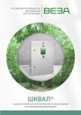
Каталог продукции Веза 2026 - Шкафы управления для систем приточно-вытяжной противодымной вентиляции ШКВАЛ. pdf, 6.57 Mb
Каталог шкафов управления ППУ ШКВАЛ для систем приточно-вытяжной противодымной вентиляции: назначение и типы, номенклатура, конструкция, габаритные размеры и масса, маркировка, схемы внешних соединений, комплект поставки. -
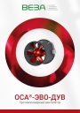
Каталог продукции Веза - Противопожарный вентилятор ОСА-ЭВО-ДУВ. pdf, 9.16 Mb
Каталог противопожарных осевых вентиляторов ОСА-ЭВО-ДУВ: назначение, конструкция и исполнения, аэродинамические и технические характеристики, габаритные размеры, обозначение при заказе. -
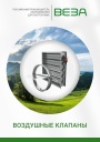
Каталог продукции Веза 2025 - Воздушные клапаны. pdf, 6.71 Mb
Каталог воздушных клапанов Веза: номенклатура, клапаны отсечные и регулирующие РЕГУЛЯР, РЕГУЛЯР-Л, РЕГЛАН, КЕДР и другие — конструкция, исполнения, приводы, технические характеристики, габаритные размеры.
Новое в инструкциях
-
Распределительные коллекторы ESBE серий GMA400 и GMA500. pdf, 15.05 Mb
Многоязычный документ с разделом на русском языке. Инструкция по монтажу распределительного коллектора для насосных групп ESBE (DN20, DN32): монтаж на стену, монтаж нескольких насосных групп. -
Напольные газовые конденсационные котлы Buderus серии Logano plus GB402. pdf, 20.72 Mb
Модели: GB402-395, GB402-470, GB402-545, GB402-620. Инструкция по монтажу и техническому обслуживанию для специалистов: технические характеристики, установка, подключение воздуховода и гидравлическое подключение, пуск в эксплуатацию, техническое обслуживание, устранение неисправностей. -

Мультисплит-системы Tosot серии Free Match. pdf, 10.22 Mb
Модели: T…H-FMA/O, T…H-FMA2/O. Руководство по эксплуатации: наружные блоки инверторной мультисплит-системы: технические характеристики, монтаж, электросхемы, коды ошибок.