

Инструкция на Внутренние блоки VRF-систем MDV серии V8 (MDVI3)
Сервисное руководство на внутренние блоки: совместимость с наружными блоками, разъёмы главной платы, настройки, панели индикации, управление, коды ошибок, поиск неисправностей. Документ на английском языке.
Смотрите также: Коды ошибок: 43 кода →
Загружаем документ…
Текст инструкции
-
R410A/R32
Commercial Air Condi�oners Service Manual VRF Indoor Units
-
Indoor and outdoor unit compatibility Before performing maintenance, please confirm that the indoor and outdoor units in the system are compatible with each other. For specific compatibility relationships, please refer to the table below. Indoor Unit V6 platform V8 platform Indoor Unit Outdoor Unit…
-
The AHU kit connects the indoor unit to the outdoor unit
Outdoor Unit Indoor unit combination V6/V6i / Combination Capacity control method V8 V6pro Platform /VX/VXi/ Mini C V6R VXpro / VC Input set Control 1 √ √ 2 / Mini C/ V5X/V4+W AHU kit -F × × × √ √ √ × × series 50%~ Outdoor unit 100% unit/Outdoor unit Input the capacity [3] Input set AHU kit -F…
-
R32 System Service Indoor units in this manual can be used with both R410A and R32 refrigerant systems. When repairing systems that use R32 refrigerant, the following warnings and opera�ng requirements should be noted. 2.1 Warning about the R32 refrigerant The following informa�on indicates a hazard…
-
– the charge size is in accordance with the room size within which the refrigerant containing parts are installed; – the ventilation machinery and outlets are operating adequately and are not obstructed; – if an indirect refrigera�ng circuit is being used, the secondary circuit shall be checked for…
-
• • evacuate; purge again with inert gas; open the circuit by cutting or brazing. The refrigerant charge shall be recovered into the correct recovery cylinders. The system shall be “flushed” with OFN to render the unit safe. This process may need to be repeated several times. Compressed air or…
-
refrigerant). Cylinders shall be complete with pressure relief valve and associated shut-off valves in good working order. Empty recovery cylinders are evacuated and, if possible, cooled before recovery occurs. The recovery equipment shall be in good working order with a set of instruc�ons…
-
CN99 A�er-sale Kit communica�on port 12VDC Standard Notes: 1. Standard: The port is standard, the customers can connect corresponding device through this port, such as water pump and Humidity sensor etc. Customized: The port is not available on the mainboard. If necessary, you need to customize the…
-
Table 3.2: voltage test instruc�ons (con�nue)
Code Content CN190 Drainage pump port Description Description When the water pump is running, pin 2 and 3 output 12V DC 1 pin CN30 Display panel Using the DC voltage gear of the mul�meter connection to test pin 1 and 4, the value should be 12V; GND GND-L 1 pin Using the DC voltage gear of the…
-
3.2 Four-way Casse�e
-
Notes
1. Standard: The port is standard, the customers can connect corresponding device through this port, such as water pump and Humidity sensor etc. Customized: The port is not available on the mainboard. If necessary, you need to customize the port Reserved: This port can not be used. 2. When…
-
3.3 Arc Duct
Figure 3.3: Arc Duct main PCB ports Troubleshooting Guide Table 3.3: Arc Duct main PCB ports Label in Figure 3.3 1 Code CN1(L.N) CN22 2 (ALARM,N,AC2 ) 3 4 CN12(H-L) CN29(H-N) CN100 Content Port voltage Note AC power input 220V AC Standard 220V AC Standard Reserved 220V AC Reserved Power supply for…
-
Table 3.4: Arc Duct main PCB ports (con�nued)
-
3.4 Medium Static Pressure Duct
Figure 3.4: Medium Sta�c Pressure Duct main PCB ports Troubleshooting Guide Table 3.5: Medium Sta�c Pressure Duct main PCB ports Label in Figure 3.4 Code 1 CN1(L.N) 2 (ALARM,N,AC2) CN22 3 4 CN12(H-L) CN29(H-N) CN100 Content Port voltage Note AC power input 220V AC Standard 220V AC Standard Reserved…
-
Table 3.5: Medium Sta�c Pressure Duct main PCB ports (con�nued)
-
3.5 Wall Mounted
-
CN99 A�er-sale Kit communica�on port 12VDC Standard Notes: 1. Standard: The port is standard, the customers can connect corresponding device through this port, such as water pump and Humidity sensor etc. Customized: The port is not available on the mainboard. If necessary, you need to customize the…
-
3.6 One-way Casse�e
-
CN100
Power supply for fan motor 23 CN99 A�er-sale Kit communica�on port Actual voltage Standard 12VDC Standard Notes: 1. Standard: The port is standard, the customers can connect corresponding device through this port, such as water pump and Humidity sensor etc. Customized: The port is not available on…
-
3.7 Two-way Casse�e
Figure 3.7: Two-way casse�e main PCB ports Troubleshooting Guide Table 3.8: Two-way casse�e main PCB ports Label in Figure 3.7 Code CN1(L.N) CN22 Content Port voltage Note AC power input 220V AC Standard 220V AC Standard Reserved 220V AC Reserved Power supply for fan motor Actual voltage Standard…
-
Table 3.8: Two-way casse�e main PCB ports (con�nued)
-
CN100
Power supply for fan motor 23 CN99 A�er-sale Kit communica�on port Actual voltage Standard 12VDC Standard Notes: 1. Standard: The port is standard, the customers can connect corresponding device through this port, such as water pump and Humidity sensor etc. Customized: The port is not available on…
-
3.9 High Static Pressure Duct (5.6-16kW)
Figure 3.9: High Sta�c Pressure Duct main PCB ports (5.6-16kW) Troubleshooting Guide Table 3.10: High Sta�c Pressure Duct main PCB ports (5.6-16kW) Label in Figure 3.9 1 2 Code CN1(L.N) CN22 (ALARM,N,AC2) Content Port voltage Note AC power input 220V AC Standard 220V AC Standard AC power output Used…
-
Table 3.10: High Sta�c Pressure Duct main PCB ports (con�nued)
-
3.10 High Static Pressure Duct (20-56kW)
-
Table 3.11: High Sta�c Pressure Duct main PCB ports (con�nued)
Label in Code Content Port voltage Note 10 CN30 Display Panel connection 12V DC[5] Standard 11 CN35 Humidity sensor connection 3.3V DC[5] Standard 12 CN5 Water level switch port 3.3V DC[5] Standard 13 CN190 Drainage pump port 12V DC[5] Standard 14 CN18 Switch module 5V/12V DC[5] Standard 15 CN16…
-
Figure 3.11: Fan module ports (20-56kW)
Troubleshooting Guide Table 3.12: High Sta�c Pressure Duct main PCB ports (con�nued) Label in Code Content 1 CN1(N) Power input 220V AC Standard 2 CN2(L) Power input 220V AC Standard 3 CN21 Reserved 220V AC Reserved 4 CN22 Reserved 220V AC Reserved 5 CN8 Main control board connection 5V DC Standard…
-
Table 3.13: voltage test instruc�ons
Label Code Content Picture 5V 5 CN8 Main control board connection GND 6 CN25 Program burning port(fan module) MDV VRF Indoor Units GND 30 5V
-
3.11 Ceiling&Floor
-
Notes
1. Standard: The port is standard, the customers can connect corresponding device through this port, such as water pump and Humidity sensor etc. Customized: The port is not available on the mainboard. If necessary, you need to customize the port Reserved: This port can not be used. 2. When…
-
3.12 Fresh Air Processing
-
Label in
Code Content Port voltage Note 15 CN25 Program burning port (indoor unit) 3.3V DC[5] Standard 16 CN8 EEV drive port 12V DC[5] Standard 17 CN30 Display panel connection 12V DC Standard 18 CN55 Remote on/off switch connection Note 5 Standard CN6(X1X2, X1 X2 communica�on port (with wire controller)…
-
3.13 Small Airflow Rate Fresh Air Processing
Figure 3.14: Small Airflow Rate Fresh Air Processing main PCB ports Troubleshooting Guide Table 3.16: Small Airflow Rate Fresh Air Processing main PCB ports Label in Figure 3.2 1 Code CN1(L,N) Content Port voltage Note AC power input 220V AC Standard 220V AC Standard / Standard 3.3V DC Standard…
-
Label in
Code Content Port voltage Note 15 CN25 Program burning port (indoor unit) 3.3V DC[5] Standard 16 CN-A Steriliza�on module port 12V DC Standard Drainage pump port 12V DC[5] Standard Standard Figure 3.2 17 CN190 18 CN8 EEV drive port 12V DC[5] 19 CN30 Display panel connection 12V DC Standard 20 CN18…
-
Table 3.17: voltage test instruc�ons (con�nue)
Code CN35 Content Humidity sensor connection Description Description Using the DC voltage gear of the mul�meter to test pin 4 and 5, the value should be 3.3V GND 3.3V 1 pin The water level is normal, the water level CN5 Water level switch switch is in the channel state; when the port water level is…
-
3.14 New One-way Casse�e
-
CN100
Power supply for fan motor 23 CN99 A�er-sale Kit communica�on port Actual voltage Standard 12VDC Standard Notes: 2. Standard: The port is standard, the customers can connect corresponding device through this port, such as water pump and Humidity sensor etc. Customized: The port is not available on…
-
4 Indoor unit set�ngs
MDV VRF Indoor Units 4.1 Parameter settings Taking KJR-86S/BK as an example, the parameters can be set in the power-on or power-off state. ①Hold " " and " " for 3 seconds to enter the parameter setting interface, and the main interface will display "CC" ② Spot check a) Wired controller Parameter…
-
Parameter
-
таблицы и схемы — в просмотре
-
Parameter
-
Parameter
Code Parameter Name Parameter Range Default Value 00: Disable Whether energy C17 efficiency attenuation is displayed when Remarks 01: Enable 00/01 00 The set�ng is valid only when the wired controller is connected to a V8 power off IDU. 00: Disable Whether IDU filter C18 blockage is displayed 01…
-
Table 4.2: Indoor unit Parameter Set�ngs
Paramete r Code Parameter Name Parameter Range Default Value Remarks IDU sta�c pressure level: N00 Sta�c pressure of IDU 00/01/02/03/ The IDU sets the selected corresponding static pressure FF 04/05/06/07/08/ (FF-there may be different default values for different series of indoor units) 09/~/19/FF…
-
Paramete
r Code Parameter Name Parameter Range Default Value Remarks 0-7 3 0-7 indicates 0 - 7°C (The value is accurate to 1°C or 1°F.) 0-10 5 0-10 indicates -4 - 6°C(The value is accurate to 1°C or 1°F.) 00/01 00 T1 temperature N13 difference for auxiliary heat source/alterna�ve heat source to turn on T1…
-
Parameter
-
Parameter
Code N35 N37 Parameter Name Q4/Q4C air outlet 4 se�ng One-to-more of wired controller enabled Parameter Range Default Value 00/01 00 00/01 00 Remarks 00 - Free control 01 - Off 00: No 01: Yes 00: Remote off (closed); N38 Remote On/Off port logic of the IDU 01: Remote off (open) 00/01 00 Note: When…
-
Parameter
Code N49 Parameter Name Condensa�on proof Parameter Range Default Value 00/01 00 Remarks 00: Invalid 01: Valid 00: Invalid N50 Human Detect Sensor 00/01/02 01 01: Used to adjust the set temperature when unattended 02: Used to turn off the unit when unattended 00: 15 min Set�ng temperature N51…
-
Parameter
Code Parameter Name Parameter Range Default Value 00/01/02 00 Ambient temperature N60 when prehea�ng is Remarks 00: 5°C turned on 01: 0°C 02: (-5)°C 00: Disconnected N61 Fresh air dry contact 1 00/01 00 01: Connected Note: Applicable to FAPU only 00: Disconnected N62 Fresh air dry contact 2 00/01 00…
-
Parameter
Code Parameter Name Parameter Range Default Value 00/01/02/03/04 00 Remarks An�-cold wind N74 temperature se�ng of 00/01/02/03: corresponds to different values; 04: An�-cold wind disabled special IDUs 00: After the remote shutdown signal is canceled, the IDU runs in the preset mode or based on the…
-
Check No
Parameters Remarks 11 Actual RH indoor humidity Actual value = value displayed 12 [―――] is displayed 13 Air discharge pipe temperature Actual value = value displayed 14 Compressor discharge temperature Actual value = value displayed 15 Target superheat Actual value = value displayed 16 EEV opening…
-
4.3 Function Descriptions
4.3.1 Power failure memory func�on The power failure memory function can be used to ensure that, in the event of a power outage, the indoor units, which was in opera�on before, automatically restart once the power returns. When the power returns following a power outage, units with Power failure…
-
Display Panels 5.1 Appearance of Display Panel The appearance of the digital display panel used is shown in Figure 5.1. Figure 5.1: Digital display panel1 Display panel for Compact Four-way Casse�e and Four-way Casse�e (New 360 degree panel, standard panel) MDV VRF Indoor Units LED display Display…
-
5.2 Output under Normal Operating Conditions
Unit state Digital display Standby Cooling and heating : set temperature Normal opera�on Opera�ng dehumidify mode: set temperature Fan only mode: indoor ambient temperature Special operation1 Mode code Error2 Error code Notes: 1. The special opera�on modes refer to Table 7.2:Opera�ng Status Codes 2.…
-
Control 6.1 Temperature Compensation Control Because of the installation position of Indoor Unit and different layout, indoor temperature detected by Indoor Unit may not consist with actual temperature. Indoor temperature could be compensated by controller (The parameter code is”N25” “N26”) 6.2 EEV…
-
6.3 Start and Stop Control
Cooling (Dry) Cooling (Dry) Cooling(Dry) T1 − T𝑠 ≥ (0 + ΔTC)℃ T1 − T𝑠<( − 1 + ΔTC)℃ Enter standby standbymode mode when when the the set isreached reached set temperature temperature is Heating T1 − T𝑠<(0 + ΔTC)℃ Heating Heating T1 − T𝑠 ≥ (1 + ΔTC)℃ Enter standby standbymode mode when when the the…
-
6.4 Fan Control
6.4.1 Fan speeds control The IDU can work in seven-speeds or three-speeds. Seven-speeds When the Indoor Unit detects seven wind speeds the wind speed is set as follows. Sleep Sleep Speed 11 Speed Speed 22 Speed Speed 33 Speed Speed 44 Speed Speed 55 Speed Speed 66 Speed Speed 7 Speed Auto Auto…
-
Determine the initial fan speed of auto fan control
The initial fan speed is determined according to the difference between ambient indoor temperature (T1) and set temperature (TS), and it updates in the following situations: 1) The first �me enter this mode 2) TS is changed 3) When switching between normal opera�on and silent opera�on 6.4.3 An�-cold…
-
6.5 Swing control
-
6.5.2 Vertical swing control
Figure 6.2 Ver�cal swing control Different IDU series have different adjustable swing angle and default swing angle under different func�ons. And each operation mode has its default adjustable range of swing angle. P1-P5 values vary because of the different operation modes and IDU series. For…
-
6.5.3 Individual louver control
Four-way Casse�e and Compact Four-way Casse�e have the individual louver control and the detail according to the following: a) Louver selection: A�er entering the louver selection operation, all air flap immediately stop at the current spot and record the current spot. If there is no parameter…
-
6.6 Operation mode control
Outdoor Unit is Heat Pump ①When the mode is set by ODU to VIP priority, Vo�ng priority, Capability requirements priority, Cooling priority, heating priority, the Indoor Unit can be set to cooling, heating, dehumidification, ventilation modes. When the IDU set mode different from the mode of ODU, the…
-
6.7 Human Detect control
The Human detect sensor is optional. The operation mode of human detect control can be set by controller (N50). 1) When set the mode "Used to adjust the set temperature when una�ended" and enter the una�ended state1, the following logic is executed ① When the cooling/automa�c cooling mode operates…
-
6.8 Controlling the Condensate Water Pump and Water Level Switch
1) 2) 3) When the IDU is powered on the first �me, the water pump is forced to operate for 5 minutes. When the IDU and ODU are in cooling, dehumidification and self-cleaning mode, the water pump starts immediately and operates continuously. A�er this mode is stopped (stop or mode switch), the water…
-
6.11 High ceiling setting
For embedded IDU series, such as Compact Four-way Cassette and Four-way Cassette, when the installation exceeds the specified height (default 3 meters), can enter the High ceiling setting ( The parameter code is”N31” ) to change . 3 meters high height, 4 meters high height or 4.5 meters high height…
-
6.13 Dry mode control
There is a difference between the control with humidity sensor and the control without humidity sensor, when the humidity sensor is damaged, the indoor unit automatically switches to the state without humidity sensor. Without humidity sensor Related settings: ①The temperature of dry mode;②Maximum…
-
Errors and opera�on code 7.1 Error Code Table Table 7.1: Error code Error Content code Emergency stop C52 A11 R32 refrigerant leaks, requiring shutdown immediately C61 A51 Outdoor unit fault C71 A72 MDV VRF Indoor Units A73 Interlocking control Heat Recovery Ven�la�on Unit fault( in-series…
-
Table 7.1: Error code(con�nues)
Error Content code E31 E32 E33 E61 E62 E81 wired controller temperature sensor failure The wireless temperature sensor short-circuits or cuts off The external room temperature sensor short-circuits or cuts off Tcp (pre-cooled fresh air temperature sensor) shortcircuits or cuts off Tph (pre-heated…
-
Troubleshooting Warning MDV VRF Indoor Units All electrical work must be carried out by competent and suitably qualified, cer�fied and accredited professionals and in accordance with all applicable legislation (all national, local and other laws, standards, codes, rules, regulations and other…
-
8.1.1 A01 – Emergency shutdown
Digital display Display position Error display Panel, display box, and wired controller The faulty IDU and other IDUs of the same system: stop running, displaying code "A01" (V6 platform indoor Error impact unit displays "A0" code) ODU of the same system: stop running, displaying code "A01" (V6…
-
8.1.2 A11 - R32 refrigerant leaks, requiring shutdown immediately
Digital display Display position Error display Panel, display box, and wired controller Faulty IDU: The fan operates at the highest speed, the EEV is closed (Note: Fault persists after power on again), and buzzer of the display control board of the faulty IDU and buzzer of wired controller connected…
-
Note 1: Adapter board ENC1 dip switch setting When the function of determining refrigerant
leakage fault is effective, if the communication abnormality between indoor unit main control board, adapter board and R32 refrigerant detection device control board lasts for more than 2 minutes (see "C79" fault handling in this manual for the communication abnormality handling method between…
-
Recharge refrigerant according to the ODU Installation Manual
(2) If the measured refrigerant saturation pressure on the liquid side or gas side is equal to the standard saturation pressure (see Table of Ambient Temperature and Standard Saturation Pressure of R32 attached to this manual), confirm whether there is a refrigerant leak by using refrigerant testing…
-
8.1.3 A51 - ODU fault
Digital display Display position Error display Panel, display box, and wired controller The faulty IDU and other IDUs of the same system: The fan continues running, the EEV is closed, and code "A51" is displayed (V6 platform IDU displays the code "Ed") Error impact ODU of the same system: stops. The…
-
8.1.4 A71 - The error of the linked FAPU is transmitted to the master IDU (series setting)
Note: 1) The type of FAPU may be HRV, VRF fresh air IDU and so on. 2) Series setting: The air supply side of the linked FAPU is directly connected to the air return side of the master IDU through an air duct. A wired controller is used to set this installation method as a series connection. Digital…
-
8.1.5 A72 - The error of the linked humidifying IDU is transmitted to the master IDU
Digital display Error display Display position (master IDU) Panel or display box Wired controller Spot check interface Error code is not query displayed Master IDU: operates normally. Humidifying IDUs: stop. Other IDUs of the same system: operate Error impact normally. ODU of the same system…
-
8.1.6 A73 - The error of the linked FAPU is transmitted to the master IDU (non-series connection)
Note: 1) The type of FAPU may be HRV, VRF fresh air IDU and so on. 2) Series setting: The linked FAPU and the master IDU are connected to the air supply duct and air return duct respectively and separately. A wired controller is used to set this installation method as a non-series connection.…
-
8.1.7 A74 - The error of the AHU Kit slave unit is sent to the master unit
Note: When multiple AHU Kits are connected in parallel, the master AHU Kit (referred to as the master) communicates with the ODU, and the slave AHU Kit (referred to as the slave) communicates with the master unit. When the slave fails, the slave unit sends a fault signal to the master unit, and the…
-
8.1.8 A81 - Self-check fault
Digital display Display position Error display Panel, display box, and wired controller Faulty IDU: stops. Other IDUs of the same system: IDUs that share the same MS with the faulty IDU will stop operating, while other IDUs remain in operation. IDUs that share the same MS with the faulty IDU display…
-
8.1.9 A82 - MS (refrigerant flow direction switching device) fault
Digital display Display position Faulty IDU Panel, display box, and wired controller Faulty IDU: The fan continues running, and the EEV is closed. Other IDUs of the same system: IDUs that share the same MS with the faulty IDU: The fan continues running, and the EEV is closed. Other IDUs remain in…
-
8.1.10 A91 - Mode conflict (V6 communication protocol adopted)
Available when using V6 platform wired controller. Digital display Display position Panel, display box, and wired controller Error display (Note: Error codes are displayed 2 minutes after faults are triggered) Faulty IDU: The fan continues running, and the EEV is closed. Other IDUs of the same…
-
8.1.11 b11, b13 - Error in 1# electronic expansion valve coil, error in 2# electronic expansion valve coil Digital display Display position Error display Panel, display box, and wired controller The faulty IDU stops. Other IDUs of the same system: operate normally. Error impact Error trigger Error…
-
1. The error code corresponds to the following two situations
a. If there is only one electronic expansion valve port on the main control board of the IDU, when an error occurs in the electronic expansion valve coil connected to the EEV port, the error code is b05. b. If there are two electronic expansion valve ports on the main control board of the IDU named…
-
8.1.12 b12, b14 - Error in 1# electronic expansion valve body, error in 2# electronic expansion valve body Digital display Display position Panel or display box Error display Spot check interface query Error impact Wired controller Error code is not displayed The faulty IDU and other IDUs of the…
-
8.1.13 b34, b35 - Stall protection for 1# water pump, stall protection on 2# water pump
Digital display Display position Error display Error impact Panel, display box, and wired controller The faulty IDU stops. Other IDUs of the same system: operate normally. ODU of the same system: operate normally. Error trigger The main control board of the IDU detects the pump rotation speed ≤ 100…
-
8.1.14 b36 - Water level switch alarm error
Digital display Display position Error display Error impact Error trigger Error recovery Panel, display box, and wired controller The faulty IDU stops. Other IDUs of the same system: operate normally. ODU of the same system: operate normally. The water level switch alarm is triggered when the…
-
1. The plug attached to the WATER port of the main control board corresponds to the following two cases: a. The factory default of IDUs without a water level switch uses a short-circuit plug to seal the WATER port. b. IDUs with a water level switch use a water level switch plug to seal the WATER…
-
8.1.15 C11 - Duplicate IDU address code
Digital display Display position Panel or display box Error display Error code and address code are displayed alternately (2) Wired controller Error code and address code flash simultaneously Faulty IDU: The fan continues running, and the EEV is closed. Other IDUs of the same system: The fan…
-
1. The following table shows the number of addresses and address codes for any indoor unit (AHU kit/direct expansion unit not applicable) with different capacities (HP) Address code to be queried at the Nominal capacity capacity (HP) (kW) Number of Number of IDUs (N) addresses (N) Address code…
-
★Example: If one IDU is 5 HP and the address code is set to 1, then the query address at the centralized controller side or wired controller side is 1. If one IDU is 20 HP and the address code is set to 5, then this IDU has four address codes, which are 5, 6, 7, and 8, but the query address at the…
-
8.1.16 C21 - Abnormal communication between IDU and ODU
Digital display Error display Display position Panel, display box, and wired controller Faulty IDU: The fan continues running, and the EEV is closed. Other IDUs of the same system: The fan continues running, the EEV is closed, and error code "A51" is displayed (V6 platform IDU displays the code…
-
If the indoor and outdoor units communicate via HyperLink (M1M2)
C21 (6) (6) If the indoor and outdoor units If the indoor and outdoor units communicate viavia HyperLink communicate HyperLink (M1M2) (M1M2) Properly the Properly connect connect the cable cable Cause 2: The repeater UP and Cause 2: The repeater UP and DOWN are not not DOWN ports are connected to…
-
Figure 1 Schematic diagram of HyperLink communication cable connection
Upstream IDU and ODU of repeater 1# (including master ODU) Master ODU IDU 10# IDU 1# Repeater 1# Repeater 2# IDU 11# IDU 20# IDU 21# Downstream IDUs of repeater 1# Upstream IDUs of repeater 2# IDU 30# Downstream IDUs of repeater 2# 1) The UP communication port of 1# repeater is connected to the…
-
8.1.17 C41 - Abnormal communication between IDU main control board and fan drive board
Digital display Display position Error display Error impact Panel, display box, and wired controller The faulty IDU stops. Other IDUs of the same system: operate normally. ODU of the same system: operate normally. Error trigger If the main control board of an IDU has lost communication with the fan…
-
8.1.18 C51: communication exception between the IDU and wired controller
Note: The error code C51 can be triggered either at the IDU side or the wired controller side. LED display Display position If a powered-on IDU does not receive any message from the wired controller: 1) Wired controller: "C51" is displayed; 2) Panel or display box: The LED display and the error code…
-
Troubleshooting
Cause 1: The communi cation wire does not meet antiinterference requirements Repl ace the communi cation wire that meets anti interference requirements Cause 2: The communi cation wire is bonded and connected or the w ire end metal oxidation exists, leading to the connection fai lure Reconnect the…
-
8.1.19 C61 - Abnormal communication between the IDU main control board and display control board
Note: The error code C61 can be triggered either at the IDU side or at the panel or display box side. Digital display Display position After power on, normal communication was not established between the indoor unit and the wired controller: 1) The wired controller does not display fault code; Error…
-
С61
C61 Cause 1:Unplug 1:Unplug the the Cause display box boxor orpanel panel display communication wire wire from from communication the the main main control control board board of of powered powered indoor indoor unit unit. Reconnect the the Reconnect communication cable cableoror communication…
-
8.1.20 C71 - Abnormal communication between AHU Kit slave unit and master unit
Note: When multiple AHU Kits are connected in parallel, the master AHU Kit (referred to as the master) communicates with the ODU, and the slave AHU Kit (referred to as the slave) communicates with the master AHU Kit. Digital display Display position (master) Error display Error impact Error trigger…
-
8.1.21 C72 - Number of AHU Kits is not the same as the set number
Note: When multiple AHU Kits are connected in parallel, the master AHU Kit (referred to as the master) communicates with the ODU, and the slave AHU Kit (referred to as the slave) communicates with the master AHU Kit. Digital display Error display Display position (master) Master AHU Kit: Display box…
-
8.1.22 C73 - Abnormal communication between the linked humidifying IDU and master IDU
Digital display Display position (master IDU) Error display Panel or display box Wired controller Spot check interface Error code is not query displayed Master IDU: operates normally. Humidifying IDUs: stop. Other IDUs of the same system: operate Error impact normally. ODU of the same system…
-
8.1.23 C74 - Abnormal communication between the linked FAPU and master IDU (series setting)
Note: 1) The type of FAPU may be HRV, VRF fresh air IDU and so on. 2) Series setting: The air supply side of the linked FAPU is directly connected to the air return side of the master IDU through an air duct. A wired controller is used to set this installation method as a series connection. Digital…
-
8.1.24 C75 - Communication fault between linked FAPU and master IDU (non-series setting)
Note: 1) The type of FAPU may be HRV, VRF fresh air IDU and so on. 2) Series setting: The linked FAPU and the master IDU are connected to the air supply duct and air return duct respectively and separately. A wired controller is used to set this installation method as a non-series connection.…
-
8.1.25 C76 - Abnormal communication between the main wired controller and secondary wired controller
Note: The error code C51 can be triggered either at the IDU side or at the wired controller side. Digital display Error display Display position The error code "C76" is displayed only on the secondary wired controller Error impact The faulty IDU and other IDUs of the same system: operate normally.…
-
8.1.26 C77, C78 - Abnormal communication between IDU main control board and 1# Expansion Board,
abnormal communication between IDU main control board and 2# Expansion Board Digital display Display position Error display Panel, display box, and wired controller Faulty IDU: The fan continues running, and the EEV is closed. Other IDUs of the same system: Error impact operate normally. ODU of the…
-
8.1.27 C79 - Abnormal communication between the IDU main control board and Switch module
Digital display Display position Error display Panel, display box, and wired controller Faulty IDU: The fan continues running, and the EEV is closed. Other IDUs of the same system: operate Error impact normally. ODU of the same system: operate normally. Error trigger If the main control board of an…
-
8.1.28 C81—The indoor unit is in a power-off state
Digital display Display position Central controller or various types of control terminal Error display software Error impact The faulty indoor unit and the panels, display boxes, and wired controllers connected to it will stop running, and the central controller or various types of control terminal…
-
8.1.29 d16 - Air inlet temperature of IDU is too low in heating mode
Digital display Display position Error display Panel, display box, and wired controller The faulty IDU stops. Other IDUs of the same system: operate normally. Error impact Error trigger ODU of the same system: operate normally. If the air inlet temperature of the IDU is lower than the set value (See…
-
8.1.30 d17 - Air inlet temperature of IDU is too high in cooling mode
Digital display Error display Display position Panel, display box, and wired controller The faulty IDU stops. Other IDUs of the same system: operate normally. Error impact MDV VRF Indoor Units Error trigger ODU of the same system: operate normally. If the air inlet temperature of the IDU is higher…
-
8.1.31 d50 - AHU kit fan running status input signal exception
LED display Display position Fault Display Panel, display box, and wired controller The faulty IDU stops. Other IDUs of the same system: operate normally. Fault Impact ODU of the same system operates normally. The V8 series AHU kit fan runs normally, but the fan ON/OFF input port on the main control…
-
8.1.32 dE1 - Sensor control board fault
Digital display Display position Error display Error impact Panel, display box, and wired controller The faulty IDU and other IDUs of the same system: operate normally. ODU of the same system: operate normally. Error trigger If the main control board of an IDU has lost communication with sensor…
-
Digital display Display position Error display Error impact Panel, display box, and wired controller The faulty IDU and other IDUs of the same system: operate normally. ODU of the same system: operate normally. Error trigger If the main control board of an IDU has lost communication with PM2.5…
-
Digital display Display position Error display Error impact Panel, display box, and wired controller The faulty IDU and other IDUs of the same system: operate normally. ODU of the same system: operate normally. Error trigger If the main control board of an IDU has lost communication with CO2 sensor…
-
8.1.35 dE4 - Formaldehyde sensor fault
Digital display Display position Error display Error impact Panel, display box, and wired controller The faulty IDU and other IDUs of the same system: operate normally. ODU of the same system: operate normally. Error trigger If the main control board of an IDU has lost communication with…
-
8.1.36 dE5 - Human Detect sensor fault
Note: The human detector sensor on the smart panel is used to detect the location of the human body. Digital display Display position Error display Error impact MDV VRF Indoor Units Error trigger Panel, wired controller The faulty IDU and other IDUs of the same system: operate normally. ODU of the…
-
8.1.37 E21, E24, E81 - T0 (fresh inlet air temperature sensor) short-circuits or cuts off, T1 (IDU return air temperature sensor) short-circuits or cuts off, and TA (outlet air temperature sensor) short-circuits or cuts off Digital display Display position Error display Error impact Panel, display…
-
sensors are short-circuited or open-circuited, but it is not able to determine if the T1 sensor is short-circuited or open-circuited. 4) Only the master unit needs to be connected to the T1/T0/TA sensors when the AHU kit is MDV VRF Indoor Units installed in parallel. 118
-
8.1.38 E31: wired controller temperature sensor failure
LED display Display position Panel or display box Fault Display Wired controller Panel, display box, and wired controller Fault Impact The faulty IDU and other IDUs of the same system operate normally. ODU of the same system operates normally. When the V8 series FAPU uses room temperature control…
-
8.1.39 EA2 - Return air humidity sensor fault
Digital display Error display Error impact Error trigger Error recovery Display position Panel or display box Wired controller Spot check interface Error code is not query displayed The faulty IDU and other IDUs of the same system: operate normally. ODU of the same system: operate normally. If the…
-
8.1.40 EC1: R32 refrigerant leakage sensor fault
LED display Display position Fault Display Panel, display box, and wired controller Faulty IDU: stops. Other IDUs of the same system: operate normally. Fault Impact ODU of the same system operates normally. Fault Trigger The IDU main control board receives sensor module fault signal from the R32…
-
Figure 1 Schematic diagram of the R32 refrigerant leakage detection system D-D: Common terminal A-A: Transmit R32 refrigerant leakage alarm signal B-B: Transmit R32 refrigerant detection device fault signal Connect an alarm or a fan Output 220VAC A-A/B-B/D-D three-core communication wire (configured…
-
8.1.41 F01, F11, F21 - T2A (heat exchanger liquid pipe temperature sensor) short-circuits or cuts off, T2 (heat exchanger middle temperature sensor) short-circuits or cuts off, and T2B (heat exchanger gas pipe temperature sensor) short-circuits or cuts off Digital display Display position Error…
-
8.1.42 P31/P34 - Fan drive board AC side overcurrent protection
Digital display Display position Error display Error impact Panel, display box, and wired controller The faulty IDU stops. Other IDUs of the same system: operate normally. ODU of the same system: operate normally. P31: The current value detected on the AC side of the fan drive board exceeds the…
-
8.1.43 P52 - The voltage of the power supply is too low
Digital display Display position Error display Error impact Panel, display box, and wired controller The faulty IDU stops. Other IDUs of the same system: operate normally. ODU of the same system: operate normally. Error trigger Power supply voltage is below the programmed protection threshold (165V)…
-
8.1.44 P71 - Main control board EEPROM fault
Digital display Display position Error display Error impact Error trigger Error recovery Possible cause Panel, display box, and wired controller The faulty IDU stops. Other IDUs of the same system: operate normally. ODU of the same system: operate normally. When the master chip cannot receive data…
-
8.1.45 P72 - IDU display control board EEPROM fault
Digital display Display position Error display Panel or display box The faulty IDU operates normally, and the error code is displayed on the panel or display box only. Other Error impact IDUs of the same system: operate normally. ODU of the same system: operate normally. Error trigger Error recovery…
-
8.1.46 U01 - Locked (electronic lock)
Digital display Display position Error display Error impact Panel, display box, and wired controller All IDUs of the same system: stop running, displaying code "U01" ODU of the same system: stops running, displaying code "U01" Error trigger When detecting that the ODU is locked Error recovery…
-
8.1.47 U11 - Unit model code not set
Digital display Display position Error display Panel, display box, and wired controller 1) The faulty IDU stops running. 2) Other IDUs of the same system: If the address for the faulty IDU has been set, other IDUs will operate normally. If the address of the faulty IDU was not set, other IDUs will…
-
8.1.48 U12 - Capacity(HP) code not set
Digital display Display position Error display Panel, display box, and wired controller 1) The faulty IDU stops running. 2) Other IDUs of the same system: If the address for the faulty IDU has been set, other IDUs will operate normally. Error impact If the address of the faulty IDU was not set…
-
8.1.49 U14 - The capacity value of the AHU Kit DIP switch does not match the model
Digital display Display position Error display Panel, display box, and wired controller 1) The faulty IDU stops running. Error impact 2) Other IDUs of the same system: operate normally ODU of the same system: operate normally Error trigger Error recovery The capacity value of the AHU Kit DIP switch…
-
8.1.50 U15 - The DIP value of AHU Kit's fan speed output voltage is incorrect
Digital display Display position Error display Panel, display box, and wired controller 1) The faulty IDU stops running. Error impact 2) Other IDUs of the same system: operate normally ODU of the same system: operate normally The voltage values corresponding to the high/medium/low speed of the AHU…
-
8.1.51 U26 - Mismatch between indoor unit model and outdoor unit model
Digital display Display position Error display Panel, display box, and wired controller 1) The faulty IDU stops running. 2) Other IDUs of the same system will operate normally Error impact ODU of the same system: If there is one IDU in the system is operating normally, the ODU will operate normally.…
-
8.1.52 U38 - Address code not detected
Digital display Display position Error display Panel, display box, and wired controller 1) The faulty IDU stops running. 2) Other IDUs of the same system: The fan continues running, the EEV is closed, and ODU error code "A51" Error impact is displayed (V6 platform IDU displays the code "Ed"). ODU of…
-
8.1.53 J01 - Motor failed more than once
Digital display Display position Error display Error impact Panel, display box, and wired controller The faulty IDU stops. Other IDUs of the same system: operate normally. ODU of the same system: operate normally. Error trigger If fan control faults have occurred 10 times in 120 min (1) Error…
-
Fault Impact
ODU of the same system operates normally. The fault is triggered if one of the following conditions is met: 1) The current value (AC) detected for any phase line of U/V/W on the IPM exceeds the set Fault Trigger overcurrent protection value of the IPM. 2) A fault signal output by the IPM protection…
-
The current value (AC) detected for any phase line of U/V/W on the IPM exceeds the set overcurrent
Fault Trigger protection value of the driver. Fault Recovery Possible Cause Automatic recovery There is no fan wheel installed on the motor. Motor coils are short-circuited, or the motor bearing is worn, resulting in an abnormal increase of motor current. The fan drive board is damaged. The IDU main…
-
8.1.56 J3E - Low bus voltage fault
Digital display Display position Panel or display box Wired controller Spot check interface query Error code is not displayed Error display Error impact The faulty IDU stops. Other IDUs of the same system: operate normally. ODU of the same system: operate normally. Error trigger When the bus voltage…
-
8.1.57 J31 - High bus voltage fault
Digital display Display position Error display Panel, display box Wired controller Error impact The faulty IDU stops. Other IDUs of the same system: operate normally. ODU of the same system: operate normally. Error trigger When the bus voltage (DC voltage) is greater than the threshold value of the…
-
8.1.58 J43 - Phase current sample bias error
Digital display Display position Error display Panel, display box Wired controller Error impact The faulty IDU stops. Other IDUs of the same system: operate normally. ODU of the same system: operate normally. Error trigger When detecting that the current sample is 50% greater than 2.5 V Error…
-
8.1.59 J45 - Motor and IDU unmatched
Digital display Display position Error display Error impact Panel, display box, and wired controller The faulty IDU stops. Other IDUs of the same system: operate normally. ODU of the same system: operate normally. Error trigger If the motor code sent by the IDU main control board is not found in the…
-
8.1.60 J47 - IPM (fan module) and IDU unmatched
Digital display Display position Error display Error impact Panel, display box, and wired controller The faulty IDU stops. Other IDUs of the same system: operate normally. ODU of the same system: operate normally. Error trigger When detecting that the fan drive board does not match the set value of…
-
8.1.61 J5E - Motor startup failure
Digital display Error display Display position Panel, display box Wired controller Error impact The faulty IDU stops. Other IDUs of the same system: operate normally. ODU of the same system: operate normally. Error trigger Motor startup failure Error recovery Automatic recovery Motor winding…
-
Panel, display box, and wired controller
The faulty IDU stops. Other IDUs of the same system: operate normally. Fault Impact ODU of the same system operates normally. Fault Trigger The motor is blocked. Fault Recovery Automatic recovery MDV VRF Indoor Units Possible Cause There is no fan wheel installed on the motor. The motor shaft gets…
-
8.1.63 J55 - Speed control mode setting error
Digital display Display position Error display Panel, display box Wired controller Error impact Error trigger Error recovery The faulty IDU stops. Other IDUs of the same system: operate normally. ODU of the same system: operate normally. The IDU is non constant air flow control, but its main control…
-
Digital display Display position Error display Panel, display box Wired controller Error impact The faulty IDU stops. Other IDUs of the same system: operate normally. ODU of the same system: operate normally. Error trigger When the motor phase lacks protection Error recovery Automatic recovery The…
-
Appendix 9.1 Temperature Sensor Resistance Characteris�cs Table 9.1: Indoor temperature sensors resistance characteris�cs R25=10KΩ±3% B25/50=4100K±3% Resistance Resistance Resistance Temperature Resistance Resistance Resistance (°C) min(kΩ) Normal(kΩ) max(kΩ) (°C) min(kΩ) Normal(kΩ) max(kΩ) -40…
-
Table 9.1: Indoor temperature sensors resistance characteris�cs(con�nues)
Resistance Resistance Resistance Temperature Resistance Resistance Resistance (°C) min(kΩ) Normal(kΩ) max(kΩ) (°C) min(kΩ) Normal(kΩ) max(kΩ) 40 4.926 5.179 5.441 80 1.060 1.166 1.281 41 4.718 4.968 5.225 81 1.025 1.128 1.240 42 4.521 4.766 5.019 82 0.990 1.091 1.201 43 4.333 4.573 4.822 83 0.958…
-
Table 9.1: Indoor temperature sensors resistance characteris�cs(con�nues)
Resistance Resistance Resistance Temperature Resistance Resistance Resistance (°C) min(kΩ) Normal(kΩ) max(kΩ) (°C) min(kΩ) Normal(kΩ) max(kΩ) 120 0.308 0.351 0.400 121 0.299 0.342 0.389 122 0.291 0.332 0.379 123 0.283 0.324 0.370 124 0.276 0.315 0.360 125 0.268 0.307 0.351 126 0.261 0.299 0.342 127…
-
9.2 Ambient Temperature and Standard Satura�on Pressure of R410A
Table 9.2: Ambient Temperature and Standard Satura�on Pressure of R410A (saturated vapor state) MDV VRF Indoor Units Ambient Saturated gauge Saturated Ambient Saturated gauge Saturated Ambient Saturated gauge Saturated gauge Temperature pressure gauge pressure Temperature pressure gauge pressure…
-
Table 9.2: Ambient Temperature and Standard Satura�on Pressure of R410A (saturated vapor state)-con�nue 50 2961.7 429.55 57 3487.2 505.78 64 4083.4 592.25 51 3032.8 439.87 58 3567.8 517.47 65 4175 605.54 52 3105.2 450.36 59 3649.9 529.38 66 4268.3 619.07 53 3178.9 461.05 60 3733.5 541.5 67 4363.5…
-
Table 9.3: Ambient Temperature and Standard Satura�on Pressure of R410A (Saturated liquid state) -con�nue 1739.6 252.31 43 2505.8 363.44 57 3495.4 506.96 30 1787.8 259.3 44 2568.5 372.54 58 3575.9 518.64 31 1837 266.43 45 2632.4 381.8 59 3657.9 530.53 32 1887.1 273.7 46 2697.5 391.24 60 3741.3…
-
9.3 Ambient Temperature and Standard Satura�on Pressure of R32
Table 9.4: Ambient Temperature and Standard Satura�on Pressure of R32 Ambient Saturated gauge Saturated Ambient Saturated gauge Saturated Ambient Saturated gauge Saturated gauge Temperature pressure gauge pressure Temperature pressure gauge pressure Temperature pressure pressure (°C) (kPa) (psi)…
-
Table 9.4: Ambient Temperature and Standard Satura�on Pressure of R32 (con�nue)
53 3263.1 473.27 59 3746.3 543.36 65 4282.9 621.19 54 3340.1 484.45 60 3831.9 555.77 66 4378 634.97 55 3418.6 495.82 61 3919 568.4 67 4474.7 649 56 3498.4 507.39 62 4007.6 581.25 68 4573.2 663.29 57 3579.6 519.17 63 4097.8 594.33 69 4673.4 677.82 58 3662.2 531.16 64 4189.6 607.64 70 4775.5 692.63…
-
S-V8IN
Ver. 2024-10 Troubleshooting Guide MDV Professional Equipment Midea Group Add.: Midea Headquarters Building, 6 Midea Avenue, Shunde, Foshan, Guangdong, China Postal code: 528311 Midea reserves the right to change the specifications of the product, and to withdraw or replace products without prior…
Схемы, таблицы и рисунки — в просмотре документа выше. Клик по номеру страницы открывает её в просмотре.
Новое в каталогах
-
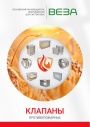
Каталог продукции Веза - Клапаны противопожарные. pdf, 77.84 Mb
Каталог противопожарных клапанов Веза (КПУ и др.): назначение, конструкция и исполнения, приводы, технические характеристики, габаритные размеры, схемы электрические подключения. -
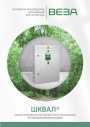
Каталог продукции Веза 2026 - Шкафы управления для систем приточно-вытяжной противодымной вентиляции ШКВАЛ. pdf, 6.57 Mb
Каталог шкафов управления ППУ ШКВАЛ для систем приточно-вытяжной противодымной вентиляции: назначение и типы, номенклатура, конструкция, габаритные размеры и масса, маркировка, схемы внешних соединений, комплект поставки. -

Каталог продукции Веза - Противопожарный вентилятор ОСА-ЭВО-ДУВ. pdf, 9.16 Mb
Каталог противопожарных осевых вентиляторов ОСА-ЭВО-ДУВ: назначение, конструкция и исполнения, аэродинамические и технические характеристики, габаритные размеры, обозначение при заказе.
Новое в инструкциях
-
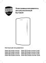
Электрические накопительные водонагреватели Royal Thermo серии Smalto Inverter. pdf, 9.20 Mb
Модели: RWH 30, 50, 80, 100 Smalto Inverter и Smalto Inverter Grafit. Инструкция пользователя: устройство, панель управления, управление с мобильного приложения, монтаж и подключение, эксплуатация, устранение неполадок, технические характеристики, габаритные размеры, гарантийный талон. -
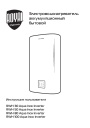
Электрические накопительные водонагреватели Royal Thermo серии Aqua Inox Inverter. pdf, 903.59 Kb
Модели: RWH 30, 50, 80, 100 Aqua Inox Inverter. Инструкция пользователя: устройство, панель управления, управление с мобильного приложения, монтаж и подключение, эксплуатация, устранение неполадок, технические характеристики, габаритные размеры, гарантийный талон. -
Электрические конвекторы Royal Thermo серии Capella RCHC/M. pdf, 5.01 Mb
Модели: RCHC/M-500, 502, 1000, 1002, 1500, 1502, 2000, 2002. Инструкция пользователя: устройство конвектора, управление прибором, уход и обслуживание, монтаж, хранение и транспортирование, технические характеристики, гарантийный талон.