

Инструкция на Контроллеры Lennox серии CLIMATIC 50, 60, 200 / 400
Контроллеры Lennox серии CLIMATIC 60 CL60 AC для чиллеров с воздушным охлаждением. Инструкция по эксплуатации.
Смотрите также: Инструкция по эксплуатации →
Загружаем документ…
Текст инструкции
-
User manual
ECOLEAN™ Air cooled chiller NEOSYS™ 9 - 1000 kW CL60 AC-CHILLER-IOM-1011-E
-
TABLE OF CONTENTS
CLIMATIC™ 60 AIR COOLED CHILLER CONTROL MANUAL Ref : CL60-AC CHILLER-IOM-1011-E INTRODUCTION CLIMATIC™ 60 controller 2 Compatibility 2 Warning 2 OVERVIEW 2 Compressor 3 Condenser fan 5 Fan SMART ACOUSTIC SYSTEM™ 7 Water evaporator 10 Changeover heating/cooling mode 14 Coil defrost 16 Free cooling 17…
-
INTRODUCTION
CLIMATIC™ 60 CONTROLLER The new generation of microprocessor based control, CLIMATIC™ 60 may be fitted to the LENNOX chiller or heat pump range. It inherits 20 years of technology and field operating experience from its predecessors the CLIMATIC™ 1, CLIMATIC™ 2 and CLIMATIC™ 50. LENNOX has found the…
-
COMPRESSOR
Function The CLIMATIC™ 60 manages the compressor(s) according to the outlet temperature demand and engages the number of compressor calculated to reach the water set point. Description The CLIMATIC™ 60 offers possibilities to disable some compressor(s) on the circuit. Note this opportunity can also…
-
“Priority C1”
The priority is fixed to circuit 1, which means circuit 1 starts first and stops the last. “Priority C2”: The priority is fixed to circuit 2, which means circuit 2 starts first and stops the last. The compressor is subject to various operating time in order to prevent from damage operating. • The…
-
CONDENSER FAN
Function The CLIMATIC™ 60 is used to maintain the high pressure as stable as possible in order to increase the performance of the unit. Description The CLIMATIC™ 60 has 2 different fan managements according to the type of unit: ECOLEAN™ (without fan speed inverter) The CLIMATIC™ 60 manages 2 speeds…
-
NEOSYS™ (with fan speed inverter)
A fan inverter controlled by a PID algorithm is used to adjust the fans speed variation. Fan's startup anticipation is forced as for the NEOSYS™ standard unit. Temperature HP (°C) Condensing set point Fan capacity (%) Time In order to optimise the performance of the unit, the condensing temperature…
-
FAN SMART ACOUSTIC SYSTEM™
Function The CLIMATIC™ 60 controls the fan speed limited by the Smart Acoustic System™ which allows progressive adaptation of the unit to the building load while respecting the noise level constraints and the operating limits. Description The maximum sound level and the fan strategies can be…
-
“Quiet++”
This mode is similar to the “Quiet” mode except that the fan speed limit or the high speed is never unlocked. In case of condensing temperature too high, the CLIMATIC™ 60 will unload a compressor to prevent from high pressure security. High speed ode ng m Cooli Low speed Stopped HP pressure (Bar)…
-
12h/24h
12h/24h C Mode D Mode 86dBA 84dBA A Mode 9h 84dBA B Mode C Mode 3h 21h 89dBA 15h D Mode 86dBA B Mode Quiet 89dBA 6h 18h Settings The different settings to adjust the acoustic mode are available in the menu: (3544): Acoustic mode (3545): Maximum sound level noise (except for fan with low / high…
-
WATER EVAPORATOR
Function The CLIMATIC™ 60 controls the chilled or heat temperature according to the specifed set point. The desired set point can be set by different solutions. Description The CLIMATIC™ 60 offers various possibilities to specify the water evaporator set point. Dynamic value The CLIMATIC™ 60…
-
External current 4/20mA signal
In this case the actual set point is calculated according to the analog input current. The set points specify the corresponding set point for 4mA and for 20mA. Cooling set point (°C) Heating set point (°C) Current input signal 4/20 mA Current input signal 4/20 mA Second external set point In this…
-
DC60 terminal
The water set point is adjustable directly by the DC60. If the read set point is different from the one calculated by the BM60, the new set point is set by the DC60 during the actual zone. Each time the zone is changing, the DC60 set point is overwriten by the CLIMATICTM60 set point. BMS value The…
-
Control
The CLIMATIC™ 60 adjusts and holds the fluid outlet temperature as close as possible to the set point, by controlling the number of compressor stages depending on the thermal load of the system. The controller constantly calculates the required capacity to reach the temperature set point. This…
-
CHANGEOVER HEATING/COOLING MODE
Function The CLIMATIC™ 60 controls the changeover mode (for reversible units only) to specify the appropriate demand on heat or chilled water production. Description The changeover can also be pre-specified according to the scheduling and can take different mode for each schedule mode (A, B, C, D…
-
Terminal DC60
The changeover mode (cool / heat) can be modified by the terminal DC60 by pressing the “mode” button. Heat → Cool → Auto → Dead zone When the “Auto” mode is selected, the icon “Cool” or “Heat” is displayed to signal the actual operating mode. Due to communication delay, after pressing the “mode”…
-
COIL DEFROST
Function The CLIMATIC™ 60 manages defrost procedure to avoid ice on the evaporator coil in heating pump mode (winter season). Description To avoid the icing of the external air exchanger during winter operating, it’s necessary to reverse the refrigerant cycle. There are 2 defrost mode: • cyclic…
-
FREE COOLING
Function The freecooling option ensures to reduce the electrical consumption using the outside air temperature to produce cool water. Description The freecooling uses water coil with helicoids fans controled by the CLIMATIC™ 60. The freecooling has a higher priority face to the compressors. Once the…
-
ELECTRONIC EXPANSION VALVE
Function The electronic expansion valve (EEV) option offers higher efficient control of the superheating temperature. Description The electronic expansion valve is driven by an external board (Electronic Valve Driver - EVD) which includes a PID algorithm to control the superheating. The EVD is…
-
ELECTRICAL HEATER
Function The electrical heater option is an additional heating capacity to help the heat pump to reach the set point during hard winter period. Description The electrical heater option has 2 uses: Antifreeze heater In this case, the heater is used to prevent the evaporator water from antifreeze. The…
-
POWER FACTOR CORRECTOR
Function The power factor correction is an additional capacitor bank to compensate the apparent power energy. Description The CLIMATIC™ 60 controls the status of the circuit breaker to inform (generate an alarm) in case of short circuit in the capacitor bank. Settings The setting to configure the…
-
PUMP EVAPORATOR MANAGEMENT
Function The CLIMATIC™ 60 offers in option a solution to manage a single or double evaporator pump(s). Description In case of double pumps, the CLIMATIC™ 60 can manage various possibilities of pumps operating. Priority to pump 1 The CLIMATIC™ 60 specifies the priority to pump 1 to start first. Pump…
-
PUMP EVAPORATOR FLOW CONTROL
Function The CLIMATIC™ 60 offers the possibility to have a flow control in option. Description There are up to 4 modes to manage the evaporator water flow. Fix speed The CLIMATIC™ 60 maintains a fix flow according to the maximum desired speed. The flow is set to the minimum desired flow only when no…
-
Fix delta of pressure
The CLIMATIC™ 60 maintains a fix delta of pressure according to the transducers (in and out) on the pump. The desired delta of pressure is customized in the menu (3345). (3345) Fix delta pressure Pressure in Pressure out (3348) Maximum 100% (3347) Minimum 60% Output flow (%) Compressor(s) Fix output…
-
PUMP CONDENSER MANAGEMENT
Function The CLIMATIC™ 60 offers in option a solution to manage a single or double condenser pump(s). Description In case of double pumps the CLIMATIC™ 60 can manage various possibilities of operating of the pumps. Priority to pump 1 The CLIMATIC™ 60 specifies the priority to pump 1 to start first.…
-
PUMP CONDENSER FLOW CONTROL
Function The CLIMATIC™ 60 offers the possibility to have flow control in option. Description Fix flow The CLIMATIC™ 60 maintains a fix flow according to the maximum desired speed. The flow is set to the minimum desired flow only when no compressor is running. Flow output Compressor(s) Fix delta of…
-
Fix delta of pressure
The CLIMATIC™ 60 maintains a fix delta of pressure according to the transducers (in and out) on the pump. The desired delta of pressure is customized in the menu (3385). (3385) Fix delta pressure Pressure in Pressure out (3388) Maximum 100% (3387) Minimum 30% → 60% Output flow (%) Compressor(s) Fix…
-
FREE INPUT/OUTPUT
Function The CLIMATIC™ 60 has free input / output on the main board BM60 and the expansion board BE60 to offer different possibilities to customize input / output for remote control of the unit. Description The free customized input / output number is: • 2 free input contacts (normally opened) on…
-
Analog input
The 4 analog inputs can be used as NTC probe (-50T90 °C; R/T 10 KΩ at 25 °C) or 4/20mA (Impedance = 100Ω) current signal. They are configurable by pair B1-B2 and B3-B4. The configuration of the type of the input is automatically set by the CLIMATIC™ 60. The analog input can be configurated to be…
-
Digital output
The 4 digital outputs are dry contacts and the maximum commutable power is 2000VA, 250Vac. The digital output can be configurated to be used as one of these items: 0. not set, 1. general alarm (alarm minor), 2. general fault (alarm major), 3. general alarm on circuit 1, 4. general alarm on circuit…
-
ON / OFF CONTROL
Function There are various ways to start up the unit: manually or automatically. Description There are up to 4 ways to start / stop the unit with the CLIMATIC™ 60: • The unit can be turned ON or OFF manually by the terminals DC60 Advanced or DS60 in the menu (2111) or (3111) or DC60. • A remote…
-
REAL TIME LOCK
Function The CLIMATIC™ 60 board includes a real time clock which permits a schedule programmation and alarm events recording. Description The clock is updated by terminal DC60 Advanced or DC60 or DS60 or BMS. Moreover, the time change is automatically updated for winter (last Sunday of October at…
-
SCHEDULING ZONE
Function The CLIMATIC™ 60 is provided by a real time clock which offers solutions to specify a weekly schedule. Description The CLIMATIC™ 60 schedule manages up to 7 different clock zones per day fand from monday to sunday. The zone can start at different time each day of the week in order to…
-
SCHEDULING MODE
Function The CLIMATIC™ 60 is able to control different modes for each zone declared in order to optimise the operating of the unit. Description The CLIMATIC™ 60 can manage up to 4 different modes. 12h/24h 12h/24h D Mode C Mode Sunday A Mode 9h 3h C Mode 21h B Mode 15h D Mode B Mode Monday 6h 18h…
-
SCHEDULE ANTICIPATION START-UP
Function The CLIMATIC™ 60 allows the start up of the unit before the pre-specified hour of the first zone (zone 1) of the day. Description This function is able to start the unit during zone 0 earlier if the outdoor temperature is under a specify threshold. The typical application is to start the…
-
MASTER / SLAVE
Function The CLIMATIC™ 60 offers possibilities to connect up to 8 units to allow relationship between each unit in order to perform the system. Unit n°1 Unit n°2 Unit n°7 Unit n°8 BM60..B. Rx-/Tx- BM60..B. Rx-/Tx- BM60..B. Rx+/Tx+ BM60..B. Rx+/Tx+ Max: 500 m The pLAN bus is connected to CLIMATIC™ 60…
-
• Chain mode: the units starts one after the other in serial sequence. In case of evaporator pump(s) in the unit, the pump(s) is engaged according to the demand of the system. Unit n°1 Unit n°2 Unit n°7 Unit n°8 100% 17% 0% 0% The backup mode Used to help the system in case of alarm(s) on the unit…
-
DC60 DISPLAY
Function The DC60 display is customized for the user to show a global operating overview of the unit and allow access to some settings. In case of remote display, the cable length should not exceed 30 m. Description The DC60 terminal displays various status of the unit and offers the possibility to…
-
Night mode,
Day mode, Day A mode, Day B mode, GTC mode The DC60 terminal also displays the status of the main component of the unit in the status area. The icons can take different appearance according to the status of the component. General alarm Defrost Evaporator pump(s) Compressors Pump OFF (icons hidden)…
-
Function The DC60 Advanced or DS60 terminals are plug and play displays, to configure the unit. • the DC60 Advanced is the display installed on the front panel of NEOSYS™ units. • the DS60 is designed for maintenance and expert service people who want to access to advanced functionalities. Language…
-
Display address
changed 5. Use the “↓”, “↑” keys to select the desired address of CLIMATIC™ 60. CLIMATIC™ 60 address must be at the address “1” except if there is several units linked. The next screen is displayed. Terminal config Press ENTER to continue 6. Press the “←” key to go to the next step. 7. The following…
-
• (1000): alarms history, • (2000): user menus for maintenance people, • (3000): (Only for DS60) Expert menus for service people (restricted area). To access to the “EXPERT” level, push the “PRG” button during few seconds when the first screen (Language) is shown. Actual zone, mode (0000) 1 | Alarm…
-
Menu (3000)
Menu (3100) Menu (3110) Menu (3160) Menu (3800) Menu (3810) Menu (3161) Menu (3169) Menu (3821) Menu (3829) Menu (3820) The “↓” and “↑” keys are used to move the cursor on the desired item. Then use the “←” key to enter in the selected submenu. To escape a menu use "ESC" the key. (3230)01 Mode A 3 |…
-
Cursor symbol for data
(3230)01 Mode A 3 > Outlet 13.3 4 | Setpoint 07.0 4 | Capacity 000.0% 4 | Air 1 22.0 4 | Air 2 30.0 4 | Water 1 07.0 4 | Water 2 07.0 Cursor symbol for set point To modify a setting, move the cursor on the desired item and press the “←” key. A new screen displays information concerning this set…
-
2212 2213 2214 2215 2216 2217 2218 2221 2222 2223 2224 2225 2226 2231 2232 2233 2234 2235 2236 2237 2238 2239 2241 2242 2243 2244 2245 2246 2247 Evaporator inlet probe T° Evaporator inlet reference T° Evaporator outlet probe T° Evaporator outlet reference T° Evaporator delta T° (Inlet-Outlet)…
-
2342 2343 2344 2345 2346 2351 2352 Condenser pump 1 status Condenser pump 1 input Condenser pump 1 output Condenser pump 1 output Condenser pump 1 output Condenser flow switch Condenser pump 2 status Condenser pump 2 input CL60-AC CHILLER-IOM-1011-E 2339 2326 Evaporator flow switch 2338 2325…
-
2418 2421 2422 2423 2424 2425 2426 2427 2428 2431 2432 Discharge T° 1 circuit 1 Discharge T° 2 circuit 1 Configuration compressor 1 circuit 1 Status compressor 1 circuit 1 Input compressor 1 circuit 1 Output compressor 1 circuit 1 Hour counter compressor 1 circuit 1 LSB Hour counter compressor 1…
-
2437 2438 2441 2442 2443 2444 2445 2446 2447 2448 Hour counter compressor 2 circuit 1 LSB Hour counter compressor 2 circuit 1 MSB Start counter high compressor 2 circuit 1 LSB (example : 123) Start counter low compressor 2 circuit 1 MSB (example 456) Configuration compressor 3 circuit 1 Status…
-
2467 2468 2471 2472 2473 2474 2475 2476 2477 2478 2481 2482 2483 2484 2485 2486 2487 2488 2491 2492 2493 2494 2511 Hour counter compressor 1 circuit 2 MSB Start counter high compressor 1 circuit 2 LSB (example : 123) Start counter low compressor 1 circuit 2 MSB (example 456) Configuration compressor…
-
2515 2516 2517 2518 2521 2522 2523 2524 2525 2526 2527 2528 2531 2532 2533 2534 2541 2542 2543 2544 2545 2551 2552 2553 2554 Input condenser circuit 1 Condensing T° circuit 1 Condensing T° set point Condensing fan capacity circuit 1 Condensing fan low speed circuit 1 Condensing fan high speed…
-
2612 2613 2614 2615 2616 2617 2618 2619 2621 2622 2623 2624 2625 2626 2627 2628 2629 2711 2712 2713 2714 2715 2716 2717 2718 2721 2722 2723 * * * * * * * * * * * * * * * * * * Configuration of the freecooling Status of the freecooling Input of the freecooling Freecooling valve Outside air T° Inlet…
-
2732 2733 2734 2735 2736 2737 2738 2739 2811 2812 2813 2814 2815 2816 2817 2818 2819 2821 2822 2823 2824 2825 2826 2827 Configuration of the electrical heater Status of the electrical heater Evaporator outler T° Electrical heater capacity Electrical heater input Electrical heater output 1 Electrical…
-
3114 3115 3116 3117 3118 3121 3122 3123 3124 3125 3131 3132 3133 Enable Test Reset the active alarm(s) Clear the historic of alarm(s) Electrical box T° General status Unit range configuration Unit size configuration Unit capacity configuration Glycol rate configuration Restore the settings…
-
3214 3215 3216 3217 3218 3221 3222 3223 3224 3225 3226 3231 3232 3233 3234 3235 3236 3237 3238 3239 3241 3242 3243 3244 3245 Evaporator outlet probe T° Evaporator outlet reference T° Evaporator delta T° (Inlet-Outlet) Evaporator set point Evaporator capacity Evaporator flow switch Changeover status…
-
3337 3338 3339 3341 3342 3343 3344 3345 3346 3347 3348 3351 3352 3353 3354 3355 3356 3361 3362 3363 3364 Evaporator delta pressure Evaporator flow capacity Evaporator flow meter Evaporator flow switch Evaporator pump(s) enable Evaporator pump(s) reset counter Evaporator pump(s) operating mode…
-
3521 3522 3523 3524 3525 3526 3527 3528 3531 3532 Condensing fan high speed circuit 1 Configuration condenser circuit 2 Status condenser circuit 2 Input condenser circuit 2 Condensing T° circuit 2 Condensing T° set point Condensing fan capacity circuit 2 Condensing fan low speed circuit 2 Condensing…
-
3544 3545 3546 3547 3548 3549 3551 3552 3553 3554 3561 3562 3563 3564 3565 3566 3567 3568 3571 3572 3573 3574 3611 3612 Condenser fan accoustic mode Condenser fan accoustic noise Condenser fan set point Condenser fan set point low speed ON Condenser fan set point low speed OFF Condenser fan set…
-
Status of the power factor correction • 62 • 3721 3631 * Configuration of the power factor correction 3629 * 3718 3628 * 3717 3627 * Freecooling fan capacity 3626 * Outlet coil water T° 3625 * 3716 3624 * 3715 3623 * Inlet coil water T° 3622 * Outside air T° 3621 * 3714 3619 * 3713 3618 *…
-
3731 3732 3733 3734 3735 3736 3737 3738 3739 3741 3742 3743 3744 3745 3746 3747 3748 3749 3811 3812 3813 3814 3815 3816 3817 3818 3819 3821 3822 Input of the power factor correction Configuration of the electrical heater Status of the electrical heater Evaporator outler T° Electrical heater capacity…
-
3827 3828 Identification number configuration BMS protocol configuration BMS bauderate configuration Minimum 3825 Watchdog timer Min 3824 Evaporator outlet BMS T° • 64 • Unit 3823 Evaporator inlet BMS T° Unit Menu Description Standard 4th digit Expert Std 2nd digit 3rd digit Link COMMUNICATION BMS…
-
Function
BMS (building management systems) are systems for the integrated management of all the technological functions of a building, including access control, safety, fire detection, lighting, intelligent elevators, and air-conditioning. The resulting advantages of such solutions are simpler and more…
-
LENNOX units implement Modbus slave protocol with the following settings
Serial Line RS485 (EIA/ TIA - 485 Standard) Transmission Mode RTU (Remote Terminal Unit) Baudrate 1200→19200 Bauds Data bits 8 bits Parity None Stop bits 1 bit The BMS mode is activated by the iinitialisation of the watchdog value. The watchdog is automatically decreasing every second. It’s…
-
ALARMS
CODE DESCRIPTION 1 Water Evaporator,Flow Switch,Cut Off 2 Water Condenser,Flow Switch,Cut Off 7 Buffer Tank,Water Level,Low 8 Buffer Tank,Water Level,High 9 Unit,Power Supply,Electrical Failure 10 Unit,Electrical Heater,Electrical Failure 21 Water Evaporator,Water T°,Outlet Too High 22 Water…
-
CODE
• 68 • DESCRIPTION 85 Water Evaporator,Water Outlet T°,Faulty Probe 89 Electrical Box T°,Air T°,Faulty Probe 90 Water Freecooling,Inlet T°,Faulty Probe 102 Circuit 1,Fan Condenser Motor,Electrical Failure 103 Circuit 1,Fan Condenser Inverter,Electrical Failure 104 Circuit 1/2,Fan Condenser…
-
CODE
DESCRIPTION 227 Circuit 2,MOP, Maximum Operating Pressure 228 Circuit 2,LOP,Low Operating Pressure 229 Circuit 2,High Condensing T° 231 Circuit 2,EEV, Valve Not Closed 232 Circuit 2,EEV, Motor 241 Circuit 2,High Pressure, Faulty Sensor 242 Circuit 2,Low Presure, Faulty Sensor 243 Circuit 2,Liquid…
-
ALARM 001
WATER EVAPORATOR, FLOW SWITCH CUT OFF Description The flow switch has detected a low water flow rate in the evaporator heat exchanger for more than 5 seconds whereas the unit was enable. Action Immediate shut down of the complete unit. Reset Once the flow has been detected for 2 minutes, the alarm…
-
ALARM 021, 022, 023, 024
WATER EVAPORATOR, OUT OF RANGE Description The water evaporator temperature (inlet or outlet) measured by the probe is outside of the permitted range. This operating range can vary according to the presence or not of glycol with the chilled water. • Alarm 021: the outlet water temperature is higher…
-
ALARM 034
ELECTRICAL BOX, AIR TEMPERATURE TOO HIGH Description The air temperature measured by the probe placed in the electrical box is too high. This alarm is managed only on NEOSYS™ units. Action If the inside temperature is higher than 62.0°C for at least 5 min, one circuit is stopped. If the inside…
-
ALARM 041, 042
PUMP EVAPORATOR, ELECTRICAL FAILURE Description The thermal magnetic circuit breaker protection of the evaporator pump 1 or 2 has tripped for 5 s, whereas the pump was in demand for at least 5 s. • Alarm 41: thermal magnetic circuit breaker protection of the pump 1, • Alarm 42: thermal magnetic…
-
ALARM 045, 046
PUMP EVAPORATOR, FAULTY PRESSURE SENSOR Description The evaporator water pressure (in or out) measured by the sensor is outside of the permitted range. This alarm is managed only if the “evaporator variable flow” option is selected. • Alarm 45: water evaporator pressure sensor IN faulty, • Alarm 46…
-
ALARM 061, 062, 063, 064, 065, 066, 067, 068
CLIMATIC BOARD LINK, FAILURE Description The link between the master / slave CLIMATIC™ 60 boards is faulty. • Alarm 61: master CLIMATIC™ 60 n°1 board disconnected, • Alarm 62 → 68: slave CLIMATIC™ 60 board n°2 → 8 disconnected. Action • Swap immediately the unit in stand alone mode. • The alarm is…
-
ALARM 071, 072
EXPANSION BOARD LINK, FAILURE Description The link between the expansion board(s) 1 or 2 and the CLIMATIC™ 60 is disconnected. • Alarm 71: the expansion board N°1 is disconnected from the CLIMATIC™ 60, • Alarm 72: the expansion board N°2 is disconnected from the CLIMATIC™ 60. Action • Immediate shut…
-
ALARM 081, 083, 085, 089, 090, 141, 142, 143, 144, 145, 146, 148, 149, 241, 242, 243, 244, 245, 246, 248, 249: PROBE & SENSOR, FAULTY Description The temperature probe or pressure sensor measured by the CLIMATIC™ 60 or other expansion boards is incorrect. The device may be disconnected or in short…
-
ALARM 102, 104, 202
CONDENSER FAN, ELECTRICAL FAILURE Description The thermal motor protection of the condenser fan has detected an over temperature for 5 s, while the fan motor was in demand for at least 5 s. • Alarm 102: thermal motor protection of the condenser fan on circuit 1, • Alarm 104: thermal motor protection…
-
ALARM 049, 050, 054, 103, 105, 203
PUMP OR FAN INVERTER, FAILURE Description The CLIMATIC™ 60 has detected an alarm on the pump inverter or the fan inverter. • Alarm 049: inverter failure of the evaporator pump, • Alarm 050: inverter failure of the condenser pump, • Alarm 054: inverter failure of the freecooling fan, • Alarm 103…
-
ALARM 111, 112, 211, 212
DISCHARGE TEMPERATURE COMPRESSOR, OVERHEATING Description The CLIMATIC™ 60 has detected an overheating discharge temperature on the compressor. • Alarm 111: overheating discharge temperature on circuit 1 – compressor 1, • Alarm 112: overheating discharge temperature on circuit 1 – compressor 2, •…
-
ALARM 115, 215
HIGH PRESSURE, CUT OFF Description The high pressure switch has trip for 5 s while a compressor was running for 10 s. • Alarm 115: high pressure cut off on circuit 1, • Alarm 215: high pressure cut off on circuit 2. Action Immediate shut down of the complete circuit. The alarm is signalling. Reset…
-
ALARM 117, 217
LOW PRESSURE, CUT OFF Description The suction temperature calculated by the LP pressure sensor is lower than the permitted threshold. The temperature has reached -27.0°C (1 minute delayed in heating mode) while a compressor was running for 30 s. The alarm is disable during 1 minute if the defrost…
-
ALARM 121, 122, 221, 222
EVAPORATOR, TEMPERATURE SUPERHEAT OUT OF RANGE Description The CLIMATIC™ 60 has detected anormal superheating temperature on the circuit. • Alarm 121: superheat temperature too high on circuit 1, • Alarm 122: superheat temperature too low on circuit 1, • Alarm 221: superheat temperature too high on…
-
ALARM 127, 227
MOP OPERARTING PRESSURE, FAULTY Description The suction pressure measured by the electronic expansion valve driver (EVD) is outside a permitted range. • Alarm 127: most operating pressure on circuit 1, • Alarm 227: most operating pressure on circuit 2. Action The circuit is still running. The alarm…
-
ALARM 129, 229
CONDENSING TEMPERATURE, TOO HIGH Description The condensing temperature measured by the CLIMATIC™ 60 is too high. • Alarm 129: high condensing temperature on circuit 1, • Alarm 229: high condensing temperature on circuit 2. Action Immediate shut down of one of the compressor on the circuit (the…
-
TABLE OF CONTENTS
CLIMATIC™ 60 AIR COOLED CHILLER APPENDIX Ref : CL60-AC CHILLER-IOM-1011-E BMS APPENDIX 1 Modbus, BACnet, Trend, Carel APPENDIX 2 BMS lonworks table CL60-AC CHILLER-IOM-1011-E_Appendix 88 95 • 87 •
-
APPENDIX 1
Modbus, BACnet, Trend, Carel • 88 • @ddress FORMAT R/W DESCRIPTION 1 Integer R/W 2 Integer 3 4 MIN MAX Counter enable BMS mode (watchdog) 0 32000 R/W Setpoint general on/off 0 1 Integer R/W Setpoint reset alarm / fault 0 1 Integer R/W Setpoint update clock Integer R/W Setpoint hour Integer R/W…
-
FORMAT
R/W DESCRIPTION 35 Integer R/W 36 Integer 37 MIN MAX [BMS] Setpoint changover cool / heat 1 4 R/W [D] Setpoint changover cool / heat 1 4 Integer R/W [D] Cooling dynamic setpoint outside air T°1 -10 30 38 Integer R/W [D] Cooling dynamic setpoint outside air T°2 -10 30 39 Integer R/W [D] Cooling…
-
Integer R/W DESCRIPTION MIN MAX R Alarm code 02 Bit00: Alarm code 98 Bit01: Alarm code 97 Bit02: Alarm code 89 Bit03: Alarm code 34 Bit04: Alarm code 83 Bit05: Not used Bit06: Not used Bit07: Not used Bit08: Not used Bit09: Not used Bit10: Not used Bit11: Not used Bit12: Not used Bit13: Not used…
-
FORMAT Integer Integer Integer Integer CL60-AC CHILLER-IOM-1011-E_Appendix R/W DESCRIPTION MIN MAX R Alarm code 07 Bit00: Alarm code 141, Bit01: Alarm code 142, Bit02: Alarm code 143, Bit03: Alarm code 144, Bit04: Alarm code 145, Bit05: Alarm code 146, Bit06: Alarm code 115, Bit07: Alarm code 117…
-
FORMAT R/W DESCRIPTION MIN MAX 0 32767 111 Integer R Alarm code 11 Bit00: Alarm code 105 Bit01: Alarm code 106 Bit02: Alarm code 107 Bit03: Alarm code 77 Bit04: Not Used Bit05: Not Used Bit06: Not Used Bit07: Not Used Bit08: Not Used Bit09: Not Used Bit10: Not Used Bit11: Not Used Bit12: Not Used…
-
FORMAT
R/W 138 Integer R 139 Integer 140 DESCRIPTION MIN MAX Output circuit 2 compresseur R Output reversing valve Integer R Output reversing valve Integer R Status condenser fan circuit Integer R Status condenser fan circuit Integer R Output electrical heater Integer R Output electrical heater Integer R…
-
Min
• 94 • @ddress FORMAT R/W 172 Integer R 173 Integer 174 DESCRIPTION MIN MAX Hour counter circuit 1 compressor 2 (LSB) 0 9999 R Hour counter circuit 1 compressor 2 (MSB) 0 9999 Integer R Hour counter circuit 1 compressor 3 (LSB) 0 9999 175 Integer R Hour counter circuit 1 compressor 3 (MSB) 0 9999…
-
R/W
R/W R/W R/W R/W R/W R/W R/W R/W R/W R/W R/W R/W R/W R/W R/W Counter enable BMS mode (watchdog) Setpoint general on/off Setpoint reset alarm / fault Setpoint reset power meter counter Setpoint override evaporator water setpoint Setpoint override cooling mode Setpoint override heating mode Setpoint…
-
R
R R R R R R R R R R R R R R R R R R R R R R R Rolling alarm code Alarm code 1 Alarm code 2 Alarm code 3 Alarm code 4 Alarm code 5 Alarm code 6 Alarm code 7 Alarm code 8 Alarm code 9 Alarm code 10 Alarm code 11 Power meter, power active Power meter, power reactive Power meter, power factor Power…
-
www.lennoxeurope.com
SALES OFFICES : BELGIUM AND LUXEMBOURG RUSSIA + 3045 +7 FRANCE SPAIN +33 +34 GERMANY UKRAINE +49 (0) 6071 3915919 +380 ITALY UNITED KINGDOM AND IRELAND + +44 1604 669 100 NETHERLANDS + POLAND +48 OTHER COUNTRIES : PORTUGAL LENNOX DISTRIBUTION +351 +33 CL60…
Схемы, таблицы и рисунки — в просмотре документа выше. Клик по номеру страницы открывает её в просмотре.
Новое в каталогах
-
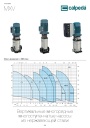
Каталог вертикальных многоступенчатых насосов Calpeda серий MXV, MXVL, MXV EI 2026. pdf, 7.05 Mb
Модели: MXV 25, 32, 40, 50, 65, 80, 100, MXVL 65, 80, MXV EI. Каталог серии: область применения, конструкция и материалы, рабочие характеристики и кривые, габаритные размеры и масса. -

Каталог осевых вентиляторов Shuft серии AXW. pdf, 4.05 Mb
Модели: AXW 4E–8DY с типоразмерами 200–910 в исполнениях S-G, S-T, B-T, B-P. Технический каталог модельного ряда: расшифровка обозначения, характеристики, схемы подключения, аэродинамические графики и габаритные чертежи. -
Каталог продукции Пульсар 2026 - Дренажные насосы. pdf, 3.91 Mb
Каталог продукции Пульсар 2026 - Дренажные насосы
Новое в инструкциях
-
Осушители воздуха Shuft серии SBW. pdf, 1.08 Mb
Модель SBW 150A. Руководство по установке и эксплуатации настенного осушителя: принцип работы, параметры моделей, размеры, проводной контроллер и пульт ДУ, схема подключения платы, монтаж, обслуживание, коды ошибок. -
Твердотопливные котлы ZOTA серии Rio с контроллером C-Line. pdf, 2.23 Mb
Модели: Rio 16, 21, 26 кВт. Паспорт и руководство по эксплуатации твердотопливных котлов ZOTA Rio с контроллером C-Line, редакция от 20.04.2026: общие сведения, технические данные, комплект поставки, меры безопасности, устройство котла, размещение и монтаж, эксплуатация, техническое обслуживание. -
Циркуляционные насосы KSB серии Calio. pdf, 7.92 Mb
Руководство по эксплуатации и монтажу высокоэффективных циркуляционных насосов Calio (оригинальное руководство KSB, док. 1157.821/13): техника безопасности, описание, установка и монтаж, ввод в эксплуатацию, управление и настройка, техобслуживание, неисправности и их устранение, схемы электрических подключений.