

Инструкция на Многоступенчатые горизонтальные центробежные насосы IMP PUMPS серии BL-H
Многоступенчатые горизонтальные центробежные насосы IMP PUMPS серии BL-H предназначены для перекачивания чистых и слегка загрязненных жидкостей с низкой вязкостью. Руководство по эксплуатации.
Загружаем документ…
Текст инструкции
-
BL-H
BL-H MULTISTAGE CENTRIFUGAL PUMPS INSTRUCTION for INSTALLATION, OPERATION & MAINTENANCE Pump Type Serial No Capacity Head Motor Power Speed : : : m³/h : m : kW : rpm
-
Contents
CONTENTS IDENTIFICATION OF SAFETY AND WARNING SYMBOLS GENERAL INSTRUCTIONS SAFETY INSTRUCTIONS i iii iii iii A- GENERAL A1- Pump Description A2- Applications A3- Pump Designation A4- Pump Nameplate A5- Technical Data B- UNCRATING, TRANSPORT AND STORAGE B1- Uncrating B2- Transport B2.1- General…
-
ii
E- LUBRICATION 10 F- DISASSEMBLY, REPAIR AND REASSEMBLY F1- Disassembly F2- Reassembly F3- Shaft Seal F3.1- Pump with soft packing gland F3.2- Pump with mechanical seal GHIJKL1L2L3N- SPARE PARTS FAULTS, CAUSES AND REMEDIES TIGHTENING TORQUES EXPECTED NOISE VALUES PERMISSIBLE FORCES AND MOMENTS AT…
-
This manual is intended to be a reference guide for users of pumps providing information on
Pump installation and maintenance instructions, Pumps start-up, operation and shut - down procedures. IDENTIFICATION OF SAFETY AND WARNING SYMBOLS Safety instructions in this manual which could cause danger to life if not observed. The presence of a dangerous electric current. ATTENTION Non…
-
BL-H PUMPS
A- GENERAL A1- Pump description BL-H series pumps are horizontal ring section multistage centrifugal pumps with closed impellers and diffusers. A2- Applications BL-H series pumps are suitable for clean or slightly contaminated (max. 20 mg/dm³) liquids with low viscosities and temperatures up to…
-
B- UNCRATING, TRANSPORT AND STORAGE
B1- Uncrating Upon receipt verify that the goods received are in exact compliance with that listed on the packing list. Check that no visible damage exists on the crate that could have occurred during transportation. Carefully remove the packaging material and check that pump and…
-
B3- Storage
If the pump is not to be installed and operated soon after arrival, store the pump in a clean, dry and frostfree place with moderate changes in ambient temperature. If the pump has regreaseable bearings, pump extra grease on bearings to prevent moisture from entering around the shaft. To…
-
Fig. 2. Foundation, baseplate and fitting the shims
Fill in the baseplate with concrete. Make no air left in it and the baseplate is well integrated with concrete foundation. Wait until the concrete firmly set (minimum 3 days). Tighten the anchor bolts. CHECK THE COUPLING ALIGNMENT AGAIN C4- Coupling Alignment a Fig. 3. Aligning a flexible…
-
C5- Connecting The Piping
C5.1- General Never use the pump as an anchorage point or as a carrier for the piping. ATTENTION The pipes should be supported very near the pump (Fig. 5). It must be checked that any weight, stress or strains on the piping system should not be transmitted to the pump.…
-
C5.3- Discharge piping (Fig. 6)
A control valve should be installed in the discharge pipe, as close to the pump as possible, to regulate the required flow and head. If the total head of the pump exceeds 10 meters or if discharge line is of appreciable length a non return valve should be installed between the pump and…
-
d3
d1 d6 d6 d5 d4 d5 d2 d7 d8 d1: Pressure gauge (discharge). d5: Seal leakage drain. d2: Pressure gauge (suction). d6: Grease nipple. d3: Air venting. d7: Flushing inlet (Mechanical seal). d4: Drain. d8: Flushing outlet (Mechanical seal). Fig. 8 C5.5- Minimum flow If there is a possibility of the pump…
-
Table 1
Motor Power PN 4 kW Motor Power PN > 4 kW power supply 3 ~ 400 V power supply 3 ~ 400 V Type of switch direct Y – connection (13b) – connection(13a) Y / - start Impossible Remove connecting bridges (13c) W2 U2 V2 U1 V1 W1 L1 L2 L3 Fig. 13a. - connection W2 U2 V2 U1 V1 W1 L1 L2 L3 Fig. 13b. Y…
-
D1.3- Venting and priming
Make sure that the pump and suction pipes are completely filled up with water. There is no problem for the pumps which have positive suction head. If there is a valve on suction line, it must be opened and air taps are loosened to enable the water replaces air in the pump, until it is completely…
-
If the pump has soft packing type stuffing boxes, these should drip during operation. The gland nuts should only be lightly tightened. In case of excessive leakage from the stuffing box tighten the gland nuts slowly and evenly until the leakage is reduced to the dripping state. Check the stuffing…
-
F- DISASEMBLY, REPAIR AND REASSEMBLY
Before starting work on the pumpset, make sure it is disconnected from the mains and can not be switched on accidentally. Follow the safety precaution measures outlined in “safety instructions”. F1- Disassembly Close all valves in the suctions and…
-
F3- Shaft Seal
F3.1- Pump with soft packing gland While starting to change soft packing thoroughly clean the stuffing box and shaft sleeve. Cut enough number of pieces at the suitable length diagonally from suitable size of soft packing. Roll it up over the shaft sleeve and see the ends are in full contact. …
-
G- SPARE PARTS
IMP PUMPS guarantees to supply the spare parts for BL-H type pumps for 10 years. You can provide any spare parts easily. Lets us know the following details on the name-plate, when you order spare parts. Pump Type and Size Motor power and Speed Prod. Year and Serial Number Capacity and Head…
-
Table 7
14 POSSIBLE CAUSES REMEDIES 1 There may be air existing in pump or suction pipe Fill pump and suction pipe completely with liquid and repeat the priming procedure. 2 Ingress of air through shaft seal, suction pipe or suction port. Pump lifts liquid with air Check for leaks in suction pipe joints and…
-
I- TIGHTENING TORQUES
-
K- PERMISSIBLE FORCES AND MOMENTS AT THE PUMP FLANGES
-
L3- SECTIONAL DRAWINGS (MECHANICAL SEAL APPLICATION)
PART LIST 004 Suction Casing 065 Shaft End Nut 220 Retaining Ring 005 006 Discharge Casing Stage Casing 067 068 Interstage Sleeve Spacer Sleeve 230 Drain Plug 231 Filling Plug 015 Diffuser 069 Spacer Sleeve 016 Final Stage Diffuser 070 Shaft Protecting Sleeve 260 300 Grease Nipple Stud *020 Wear…
-
M- COUPLING GUARD AND SAFETY GUARD
B A B Safety guard Note: All guards are conforming to EN 294. 20 A Coupling guard
Схемы, таблицы и рисунки — в просмотре документа выше. Клик по номеру страницы открывает её в просмотре.
Новое в каталогах
-
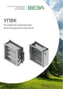
Каталог продукции Веза 2025 - Устройства перекрытия вентиляционных каналов УПВК. pdf, 1012.56 Kb
Каталог устройств перекрытия вентиляционных каналов УПВК: назначение, конструкция, технические характеристики, габаритные размеры, обозначение при заказе. -

Каталог продукции Веза 2025 - Шкафы систем автоматического управления ШСАУ ВЕРСА 100 - 400. pdf, 16.08 Mb
Каталог шкафов систем автоматического управления ШСАУ ВЕРСА 100–400: назначение, функции, исполнения, схемы, технические характеристики, обозначение при заказе. -

Каталог продукции Веза 2025 - Системы канальной вентиляции. pdf, 8.54 Mb
Каталог оборудования Веза для канальной вентиляции: канальные вентиляторы, нагреватели, охладители, фильтры, шумоглушители, клапаны — технические характеристики и габаритные размеры.
Новое в инструкциях
-

Электрические конвекторы Royal Thermo серии Capella RCHC/E. pdf, 5.01 Mb
Модели: RCHC/E-500, 502, 1000, 1002, 1500, 1502, 2000, 2002. Инструкция пользователя: устройство конвектора, управление прибором, уход и обслуживание, монтаж, хранение и транспортирование, технические характеристики, гарантийный талон. -

Бойлеры косвенного нагрева Royal Thermo. Правила установки. pdf, 251.55 Kb
Схема-памятка по установке бойлера косвенного нагрева: подключение к котлу и контурам ГВС/ХВС, группа безопасности, расширительный бак, диэлектрические муфты, фильтр очистки воды, заземление. -

Инверторные сплит-системы Shuft серии Asgard DC. pdf, 8.78 Mb
Модели: SFTHAI/IN-07HN8/BL, 09HN8/BL, 12HN8/BL, SFTHAI/OUT-07HN8/BL, 09HN8/BL, 12HN8/BL. Руководство по эксплуатации: монтажная схема и монтаж, описание пульта управления и режимов работы, Wi-Fi и мобильное приложение, уход и обслуживание, технические характеристики, устранение неисправностей, протоколы приёмки и тестового запуска, гарантийный талон.