

Инструкция на Контроллер TLK 43
Цифровой электронный контролллер TLK 43. Инструкция по монтажу и эксплуатации.
Загружаем документ…
Текст инструкции
-
TLK 43
MICROPROCESSOR-BASED DIGITAL ELECTRONIC CONTROLLER OPERATING INSTRUCTIONS Vr. 02 (ENG) - cod.: ISTR 6267 FOREWORD: This manual contains the information necessary for the product to be installed correctly and also instructions for its maintenance and use; we therefore recommend that the utmost…
-
the previous programming level until he exits the programming
mode. Outside the programming mode it permits visualisation of the current measured by the TAHB input, on the SV display. 3 - Key UP : This is used to increase the values to be set and to select the parameters. If the key is held down, the user returns to the previous programming level until he…
-
one supplied and can be modified using the “UP” and “DOWN”
keys. In case of ON/OFF control, 0% corresponds to the deactivated output while any value different from 0 corresponds to the activated output. As in the case of visualization, the programmable values range from H100 (100% output power with reverse action) to C100 (100% output power with direct…
-
Connect the instrument as far away as possible from sources of
electromagnetic disturbances such as motors, power relays, relays, solenoid valves, etc. The instrument can be removed from its housing from the front side : it is recommended that the instrument be disconnected from the power supply when it is necessary to carry out this operation. 3.3 - ELECTRICAL…
-
event of probe error with ON/OFF control and “OPE”=50, the control output will be activated for 10 sec., then it will be deactivated for 10 sec. and so on until the measurement error remains.). By using par. “ InE” it is also possible to decide the conditions of the input error, allowing the…
-
4.5 – SINGLE ACTION PID CONTROL (1rEG)
All the parameters referring to PID control are contained in the ] group “ rEG”. The Single Action PID control can be obtained by programming par."Cont" = Pid and works on the output 1rEG depending on the active Set Point “SP” , on the functioning mode "Func” and on the instrument’s PID algorithm…
-
"cLoS") for the time set on parameter "tcor" after which control
begins. In the event of an error in measurement, the outputs are activated so that the valve moves to the position fixed by the parameter “PoSI”. The Auto-tuning cycle duration has been limited to 12 hours maximum. If Auto-tuning is not completed within 12 hours, the instrument will show "noAt" on…
-
4.11 - SPLIT RANGE FUNCTION
The use of this function is only possible if the PID control is dual function and can be used to delay or bring forward the intervention of the actuators commanded by the instrument. Using this function it is therefore possible to optimise the intervention of the two actuators in such a way that…
-
function is not deactivated when the automatic control power is found to be lower than the programmed one. 2) If par. “St.P” = OFF and a value is set on par. “SSt” , at the switch on, the power calculated by the PID controller is divided by the time “SSt”, in order to calculate a ramp. The output…
-
ALARM DELAY: the alarm output may behave in two different ways
depending on the value added to par. “Abn”. +0 = ALARM NOT DELAYED: The alarm is immediately activated when the alarm condition occurs. +2 = ALARM DELAYED: When the alarm condition occurs, delay counting begins, as programmed on par. “ALnd” (expressed in sec.) and the alarm will be activated only…
-
Enter group “ LbA” and program which output the alarm signal has to be addressed to on par. “ OLbA” . The Loop Break alarm is activated if the output power remains at the 100% of the value for the time programmed on par. "LbAt" (expressed in sec.). To avoid false alarms, the value of this parameter…
-
P.A.: For the instruments equipped with RS485 serial Group “ InP” (parameters relative to the measure input) communication, it’s indispensable that the parameter “PACS” is Par. Description Range Def. programmed = LorE. 9 HCFG Input type tc / rtd / I / tc UoLt / SEr To transfer the configuration of…
-
analogical output 2 for signal retransmission 31 Ao2H Maximum reference for Ao2L ÷ 9999 analogical output 2 for signal retransmission Group “O3” (parameters relative to output 3) Par. Description Range 32 O3F Functioning of output 3 1.rEG / 2.rEG ALno / ALnc OFF Group “O4” (parameters relative to…
-
dur.t Duration time 0.00 ÷ 99.59 InF / InF hrs.-min. 86 SLoF Gradient of fall ramp 0.00 ÷ 99.99 InF / InF unit / min. 87 ro1.L Minimum power in 0 ÷ ro1.H 0 output from 1rEG % 88 ro1.H Maximum power from ro1.L ÷ 100 100 output from 1rEG % 89 ro2.L Minimum power in 0 ÷ ro2.H 0 output from 2rEG % 90…
-
7.2 – MECHANICAL DATA
-
7.6 – INSTRUMENT ORDERING CODE
TLK 43 a b c d e f g h ii a : POWER SUPPLY L = 24 VAC/VDC H = 100 240 VAC b : OUTPUT OUT1 R = Relay O = Voltage VDC for SSR C = Analogue 0/4 ..20 mA V = Analogue 0/2 10 V c : OUTPUT OUT2 R = Relay O = Voltage VDC for SSR C = Analogue 0/4 ..20 mA V = Analogue 0/2 10 V - = None d : OUTPUT OUT3 R =…
Схемы, таблицы и рисунки — в просмотре документа выше. Клик по номеру страницы открывает её в просмотре.
Новое в каталогах
-
Каталог продукции Веза 2026 - Оборудование для окрасочных камер. pdf, 5.13 Mb
Каталог оборудования Веза для окрасочных камер: центральные кондиционеры ВЕРОСА-600, вентиляторы радиальные и общепромышленные и другое оборудование — технические характеристики, габаритные размеры. -
Каталог продукции Мовен 2004 - Оборудование для систем дымозащиты: вентиляторы, клапаны. pdf, 3.93 Mb
Каталог оборудования для систем противодымной защиты: радиальные вентиляторы дымоудаления ВР-280-46ДУ, ВР-86-77ДУ, ВР-80-70ДУ, осевые ВО-13-284ДУ, крышные ВКРМ ДУ, осевые вентиляторы подпора воздуха ВО-25-188 и ВО-14-320, клапаны КП-Ф1, КДФ-1, КДП 5А, огнезадерживающие клапаны АЗЕ-МФ, противопожарные двери и люки. -
Каталог продукции Мовен - Вентиляторы общего и специального назначения. pdf, 13.05 Mb
Каталог вентиляторов общего и специального назначения Московского вентиляторного завода (торговая марка МОВЕН): общие сведения о комплектации и условиях работы, радиальные вентиляторы низкого, среднего и высокого давления, осевые и крышные вентиляторы, вентиляторы дымоудаления, взрывозащищённые, пылевые и судовые вентиляторы, аэродинамические характеристики и габаритные размеры.
Новое в инструкциях
-
Вентиляторы в круглом корпусе Shuft серии SH. pdf, 646.47 Kb
Модели: SH 160, 200, 250, 315, 400. Руководство по установке, эксплуатации и техническому обслуживанию: технические характеристики, размеры, монтаж, электрические подключения, ввод в эксплуатацию, обслуживание и чистка, устранение неисправностей. -
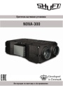
Приточно-вытяжные установки Shuft серии NOVA. pdf, 4.29 Mb
Модель NOVA-300. Инструкция по монтажу и обслуживанию: принципиальная схема установки, массогабаритные показатели, монтаж воздуховодов и дренажа, подключение электропитания, схема электрических соединений, пусконаладка, обслуживание, неисправности, подключение к системе диспетчеризации. -
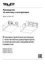
Компактные приточно-вытяжные установки Shuft серии UniMAX-P CE-A. pdf, 8.10 Mb
Модели: UniMAX-P 450 CE-A, 800 CE-A, 1000 CE-A, 1500 CE-A. Руководство по монтажу и эксплуатации подвесных установок с пластинчатым рекуператором и электронагревателем: характеристики, монтаж, схемы подключений, пусконаладка, пульт управления, техническое обслуживание, неисправности.