

Инструкция на Внутренние блоки для системы VRF.
R 407 C, R 22.Внутренние блоки кассетные компактные для системы VRF. Инструкция по монтажу.
Смотрите также: Руководство по монтажу →
Загружаем документ…
Текст инструкции
-
STANDARD PARTS
The following installation parts are supplied. Use them as required. INDOOR UNIT ACCESSORIES Name and Shape Coupler heat insulation Special nut A (large flange) Special nut B (small flange) Q’ty Name and Shape GRILLE ACCESSORIES Name and Shape Q’ty Bolt Template 2 Q’ty 4 1 Washer Binder Blower cover…
-
INSTALLATION PROCEDURE
Install the air conditioner as follows. 1. INDOOR UNIT INSTALLATION (1) Make the holes for installing in the ceiling. (Fig. 4) (2) Install the hanging bolts (M10), refer to the position in Fig. 3. (3) Install special nut A, then special nut B onto the hanging bolt (Fig. 4). (4) Raise the body and…
-
3. CONNECTION PIPE REQUIREMENT
(1) Connected to outdoor unit Table 1 unit : mm Capacity of outdoor unit Suction Gas Pipe Discharge Gas Pipe Liquid Pipe 90 ø28.58 (1.2) ø19.05 (1.0) ø12.7 (0.8) ( ) : thickness (2) Connected between two immediately adjacent refrigerant branch kits Table 2 Total capacity of indoor unit unit : mm…
-
2. CONNECTION PIPES
When the flare nut is tightened properly by your hand, hold the body side coupling with a separate spanner, then tighten with a torque wrench (Fig. 8, Table 5). Fig. 8 Holding spanner Fig. 7 Body side Indoor unit Liquid pipe Gas pipe Torque wrench Table 5: Flare nut tightening torque Flare nut…
-
6. ELECTRICAL REQUIREMENT
Table 6 Power supply cord (mm2) Transmission cord (mm2) Remote control cord (mm2) Maximum 2.5 Minimum 1.5 Maximum 1.25 Minimum 0.75 Maximum 1.25 Minimum 0.75 Fuse capacity (A) H07RN-F or equivalent Shield cord (LONWORKS compatible part) Sheathed vinyl cord or cable 20 7. ELECTRICAL WIRING WARNING 1…
-
Fig. 11
Terminal board Remote controller RB unit cord (Heat recovery model only) Transmission cord Remote control cord Power supply cord Note that the arrangement of the terminal board may vary from model to model. Refrigerant branch unit (Heat recovery model only) 380-415 V 3ø 50 Hz 220-240 V 1ø 50 Hz…
-
8. CIRCUIT BOARD SETTING
Set the switch on the circuit board. (1) Indoor unit addresses Rotary switch (SW5) - - - Factory setting “0” When connecting multiple indoor units to one refrigerant system, set the address at SW5 in sequence from 0. (2) Refrigerant circuit address Rotary switch (SW7) - - - Factory setting “0”…
-
(3) Remote controller address
Rotary switch (SW9) - - - Factory setting “0” When connecting multiple indoor units to one standard wired remote controller, set the address at SW9 in sequence from 0. Fig. 12 Example If 4 indoor units are connected. Indoor unit Indoor unit Indoor unit Indoor unit R-SW9 0 R-SW9 1 R-SW9 2 R-SW9 3…
-
9. GRILLE INSTALLATION
1. INSTALLING BLOWER COVER INSULATION (IN CASE OF 2 OR 3 OUTLET DIRECTION) • Install the blower cover insulation only when the outlet direction is changed to 2 or 3 direction. • Two blower cover insulations are packed with the grille assembly. • Install the blower cover insulation at the diffuser…
-
Installing the grille assembly to the body
Install the grille assembly to the body with the four bolts and washers. (1) Lightly tighten the bolts shown in “B” of Fig. 15. Hang the panel. (2) Tighten the other bolts. (3) Tighten all bolts securely. (4) Connect the connector in accordance with part A detail view. (Fig. 16) Fig. 15 Fig. 16 Part…
-
REMOVING THE INTAKE GRILLE
(1) Slide the two grille stoppers inward, then open the intake grille. (2) Remove the grille hook screws, then open the intake grille. (Fig. 19) (3) Open the intake grille so that it is at an angle of 20° to 40°, then remove the grille. Fig. 19 Grille hook CAUTION 1 The louver angle cannot be…
-
10. TEST OPERATION
Supply power to the crankcase heater for 12 hours prior to the start of operation in the winter. The following is the procedure for the test operation. 1. TEST OPERATION USING CIRCUIT BOARD (OUTDOOR UNIT) Refer to the Installation Instruction Sheet for the outdoor unit if the circuit board for the…
-
Fig. 22
(2) Standard wireless remote controller • Press the remote control unit test run button while the air conditioner is running. • At the end of test running, press the remote control unit startstop button (Fig. 22). Operation can be checked by lighting and flashing of the display section OPERATION and…
-
Table 10
Error display OPERATION lamp TIMER lamp Error contents VERTICAL SWING lamp Blinks Blinks Goes off Model information abnormal Blinks Blinks Blinks Power supply frequency abnormal Pulses 2times Blinks Goes off Room temperature thermistor error Pulses 3times Blinks Pulses 1time Indoor unit heat…
Схемы, таблицы и рисунки — в просмотре документа выше. Клик по номеру страницы открывает её в просмотре.
Новое в каталогах
-

Каталог продукции Веза 2026 - Вентиляторы осевые ОСА-ЭВО. pdf, 8.81 Mb
Каталог осевых вентиляторов ОСА-ЭВО: назначение, конструкция и исполнения, аэродинамические и технические характеристики, габаритные размеры, обозначение при заказе. -
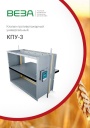
Каталог продукции Веза - Клапан противопожарный универсальный КПУ-3. pdf, 990.15 Kb
Каталог универсального противопожарного клапана КПУ-3: назначение, конструкция, приводы, технические характеристики, габаритные размеры, обозначение при заказе. -
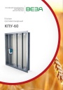
Каталог продукции Веза - Клапан противопожарный КПУ-60. pdf, 839.50 Kb
Каталог противопожарного клапана КПУ-60: назначение, конструкция, приводы, технические характеристики, габаритные размеры, обозначение при заказе.
Новое в инструкциях
-
Вентиляторы в круглом корпусе Shuft серии SH. pdf, 646.47 Kb
Модели: SH 160, 200, 250, 315, 400. Руководство по установке, эксплуатации и техническому обслуживанию: технические характеристики, размеры, монтаж, электрические подключения, ввод в эксплуатацию, обслуживание и чистка, устранение неисправностей. -
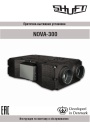
Приточно-вытяжные установки Shuft серии NOVA. pdf, 4.29 Mb
Модель NOVA-300. Инструкция по монтажу и обслуживанию: принципиальная схема установки, массогабаритные показатели, монтаж воздуховодов и дренажа, подключение электропитания, схема электрических соединений, пусконаладка, обслуживание, неисправности, подключение к системе диспетчеризации. -
Компактные приточно-вытяжные установки Shuft серии UniMAX-P CE-A. pdf, 8.10 Mb
Модели: UniMAX-P 450 CE-A, 800 CE-A, 1000 CE-A, 1500 CE-A. Руководство по монтажу и эксплуатации подвесных установок с пластинчатым рекуператором и электронагревателем: характеристики, монтаж, схемы подключений, пусконаладка, пульт управления, техническое обслуживание, неисправности.