

Инструкции на Гибридные инверторы Fronius Symo Hybrid
Гибридные инверторы Fronius Symo Hybrid. Pуководствo по эксплуатации и установке.
Загружаем документ…
Текст инструкции
-
/ Perfect Charging / Perfect Welding / Solar Energy
FIND YOUR OPERATING MANUALS www.fronius-usa.com/inverter-manuals www.fronius.com/energy-package-manuals 42,0426,0303,EN 015-12082019 Installations instructions EN Fronius Symo Hybrid with external battery System monitoring
-
Contents
Connecting the external battery to the Fronius Symo Hybrid Components Fronius Checkbox 500V External battery Fronius Checkbox 500V technical data Fronius Checkbox 500V status LED Installing the Fronius Symo Hybrid with the external battery Tips before commissioning Commissioning Maximum clearances…
-
Components
Solar module Generates direct current Inverter – Fronius hybrid Converts the direct current into alternating current and charges the battery. Thanks to the built-in system monitoring function, the inverter can be integrated into a network using WLAN technology. Fronius Checkbox 500V Needed to…
-
Fronius Checkbox 500V technical data
Environmental conditions Degree of protection IP65 Permissible ambient temperature -25 °C - +60 °C Maximum altitude 2000 m Permitted humidity 0 - 100% (non-condensing) Electrical specifications Maximum input voltage Inverter side Battery side Udc max in_INV Udc max out_BAT Maximum current Idc max in…
-
Tips before commissioning
It can take up to two hours to update the inverter. During this time the inverter must be connected to an AC power source. To save time during installation, work may still be carried out in a non-live area of the system while the update is in progress. More information on the update process can be…
-
Modbus cabling
and terminating resistors A terminating resistor must be used on the outer components of the Modbus cabling. The location of the terminating resistor on the external battery is fixed, meaning that the battery cannot be installed in the middle of the Modbus. OPTION 1 OUTPUT Fronius Smart Meter…
-
Installing the Fronius Checkbox
Safety WARNING! Operating the equipment incorrectly or poor workmanship can cause serious injury or damage. Commissioning of the hybrid system may only be carried out by trained personnel in accordance with the technical regulations. Read the Installation Instructions and the Operating Instructions…
-
Mounting and
connecting up the Fronius Checkbox 500V NOTE! Risk of damage to the device. Do not mix up the DC connections of the battery and the inverter. Observe the enclosed complete circuit diagram when connecting up the Fronius checkbox. 1 1 Mount the supplied mounting bracket to the wall using suitable…
-
Safety
WARNING! Danger from incorrect operation This can result in severe personal injury and damage to property. ► Do not use the functions described here until you have fully read and understood the Operating Instructions of every system component: ► Do not use the functions described here until you have…
-
Installation using the Solar.web app
2 3 Download the Fronius Solar.web App Installation using a web browser 2 Connect the end device to the WLAN access point SSID = FRONIUS_239.xxxxx (4-8 digits) Search for a network with the name "FRONIUS_239.xxxxx" Establish a connection to this network Enter the password 12345678 Run the Fronius…
-
Danger of deep discharge of an unactivated battery
This may result in permanent damage to the battery. ► The Solar Web wizard needs to be run in order to activate the battery and, if necessary, the Smart Meter. 5 Run the solar web wizard and follow the instructions The Fronius Solar.web homepage or the Fronius system monitoring web page is…
-
3. IO mapping
Settings for the IO interface are entered (also see Creating IO mapping on page 17) 4. System overview Settings for the entire PV system are entered (see also System monitoring settings on page 17) 5. Dynamic power Enter the settings for the dynamic power reduction Software version of the Fronius…
-
Regardless of the software version shown in the web interface, it may take several update
steps before the software is updated to the latest version. Both the inverter and the battery can be updated at the same time. Updating the firmware via the Web 1 Use your web browser to open the Fronius system monitoring web page. 2 Open “Firmware update” under “Services”. 3 Select 'Update via Web'…
-
2 A page containing a variety of setting options appears. Under "Update", select "Local" and click on "Run update" 3 The update will start and run to completion. This can take up to an hour. Wait until the end of the update. 4 A message will appear stating that the update was successful. Confirm the…
-
Fronius system monitoring settings
Settings on the Fronius system monitoring website If the battery is installed at a later date or the inverter was only updated to software version 1.9.x-x after the system had already been commissioned, several settings will need to be changed on the system monitoring website. In the "IO mapping"…
-
Troubleshooting
Troubleshooting 18 Battery is permanently in energy saving mode (error message 65000) Behaviour The battery goes into energy saving mode and can no longer be activated by the inverter Remedy Check if the DC main switch on the battery has been switched on Remedy Check if the DC main switch on the…
-
Other Languages
Deutsch English Deutsch English Ceština Italiano Français Español www.fronius.com/QR-link/4204260303DE www.fronius.com/QR-link/4204260303EN www.fronius.com/QR-link/4204260303CS www.fronius.com/QR-link/4204260303IT www.fronius.com/QR-link/4204260303FR www.fronius.com/QR-link/4204260303ES Dansk Svensk…
Схемы, таблицы и рисунки — в просмотре документа выше. Клик по номеру страницы открывает её в просмотре.
Другие файлы документа
Новое в каталогах
-
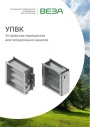
Каталог продукции Веза 2025 - Устройства перекрытия вентиляционных каналов УПВК. pdf, 1012.56 Kb
Каталог устройств перекрытия вентиляционных каналов УПВК: назначение, конструкция, технические характеристики, габаритные размеры, обозначение при заказе. -

Каталог продукции Веза 2025 - Шкафы систем автоматического управления ШСАУ ВЕРСА 100 - 400. pdf, 16.08 Mb
Каталог шкафов систем автоматического управления ШСАУ ВЕРСА 100–400: назначение, функции, исполнения, схемы, технические характеристики, обозначение при заказе. -

Каталог продукции Веза 2025 - Системы канальной вентиляции. pdf, 8.54 Mb
Каталог оборудования Веза для канальной вентиляции: канальные вентиляторы, нагреватели, охладители, фильтры, шумоглушители, клапаны — технические характеристики и габаритные размеры.
Новое в инструкциях
-
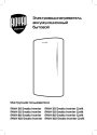
Электрические накопительные водонагреватели Royal Thermo серии Smalto Inverter. pdf, 9.20 Mb
Модели: RWH 30, 50, 80, 100 Smalto Inverter и Smalto Inverter Grafit. Инструкция пользователя: устройство, панель управления, управление с мобильного приложения, монтаж и подключение, эксплуатация, устранение неполадок, технические характеристики, габаритные размеры, гарантийный талон. -
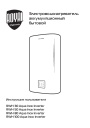
Электрические накопительные водонагреватели Royal Thermo серии Aqua Inox Inverter. pdf, 903.59 Kb
Модели: RWH 30, 50, 80, 100 Aqua Inox Inverter. Инструкция пользователя: устройство, панель управления, управление с мобильного приложения, монтаж и подключение, эксплуатация, устранение неполадок, технические характеристики, габаритные размеры, гарантийный талон. -
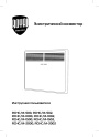
Электрические конвекторы Royal Thermo серии Capella RCHC/M. pdf, 5.01 Mb
Модели: RCHC/M-500, 502, 1000, 1002, 1500, 1502, 2000, 2002. Инструкция пользователя: устройство конвектора, управление прибором, уход и обслуживание, монтаж, хранение и транспортирование, технические характеристики, гарантийный талон.