

Инструкция на Котлы газовые конденсационные ENERGY TOP
Буклет.
Загружаем документ…
Текст инструкции
-
Ferroli
ENERGY TOP sing boiler solutio
-
Introduction
THE ENERGY TOP SYSTEM The increasing need for families to be able to manage their central heating system freely and independently has in recent years led to the expansion of independent systems, gaining ground over the traditional centralised approached to heating. Independent systems have been and…
-
The heart
FURNACE The HEART of ENERGY TOP is an innovative heating unit that ensures the product excellent characteristics in terms of efficiency and flexible modulation. The new total premixed air-gas combustion unit with variable speed fan, pneumatic gas valve and cylindrical metal fibre burner allows a…
-
The mind
ELECTRONIC CONTROL The ENERGY TOP series generators feature evolved electronics that can control the heating units making up the module in complete safety and autonomy. A large backlit LCD is fitted to make it easier to read the boiler data and set the configuration parameters. The electronics on…
-
ELECTRONIC CONTROL ENERGY TOP
In particular, the 0-10 Volt input signal on the electronics for each furnace means the heat generators can interface to any generic external control unit featuring a 0-10 Volt output. In this way, the ENERGY TOP series generators can be very easily installed in existing systems with electronic…
-
The range
The ENERGY TOP W series boilers are wall-hung heat generators for inside or outside installation, central heating only, featuring a premix burner, condensing operation with very high efficiency and very low polluting emissions. They consequently ensure high energy savings and are…
-
Technical specifications
ENERGY TOP Output and Efficiency Heat input, central heating Heat output, central heating Efficiency max kW min kW max (80-60°C) kW min (80-60°C) kW max (50-30°C) kW min (50-30°C) kW Pmax (80-60°C) % Pmin (80-60°C) % Pmax (50-30°C) % Pmin (50-30°C) % 30% (30°C) % Efficiency class Directive 92/42 EEC…
-
The water circuit
The water circuit is simple, rational and allows easy access to the inside components. Key 7 Gas inlet 10 Central heating flow outlet 11 Central heating return inlet 16 Fan 22 Main burner 29 Flue gas outlet manifold 36 Automatic air vent 44 Gas valve 82 Detection electrode 114 Water pressure switch…
-
Cascading
A series of water circuit accessories and self-supporting frames is available for the ENERGY TOP W wall-hung modules, used to create different cascading configurations. The structure is self-supporting and does not need to be anchored to the walls. This means the boilers do not necessarily need to…
-
Various solutions are available for the air intake and flue gas outlet on the ENERGY TOP W wall-hung
modules, for both installation on individual and multiple modules. The low flue gas temperature means special polypropylene accessories can be used. As regards the single discharge system, both 80 mm separate and 80/125 mm coaxial flue gas outlet configurations are available, with combustion intake…
-
The ENERGY TOP W series modules are fitted with evolved electronics that as standard can
manage up to two system zones (direct outlet) or an optional storage cylinder with one direct zone, without requiring further control boards. MIXED DIAGRAM WITH PRIORITY TO THE STORAGE CYLINDER Each module or series of modules can be connected to an outside temperature probe for temperature…
-
CENTRAL HEATING ONLY DIAGRAM WITH DIRECT OUTLET
Control units can be added to directly manage up to two circuits, with direct outlet. MIXED DIAGRAM WITH STORAGE CYLINDER AND DIRECT OR MIXED CENTRAL HEATING CIRCUITS More complex system diagrams, on the other hand, can be managed by using zone control units that can “dialogue” directly with the…
-
Modules — 80 — — Modules 4 — — — — — 80 — 80 — ENERGY TOP W models 042033X0 qt 042021X0 qt 043005X0 qt 041026X0 qt 041028X0 042028X0 qt qt BASIC COMPONENTS 042031X0 qt 042029X0 qt 042032X0 qt 042030X0 qt — — — — — 013013X0 1KWMA62U 043005X0 041019X0 qt qt qt qt x x x x x x x x x x x x OPTIONAL…
-
The range
The ENERGY TOP B cabinet modules are floor-standing heat generators for inside or outside installation, central heating only, featuring a premix burner, condensing operation with very high efficiency and very low polluting emissions. They consequently ensure high energy savings and are…
-
Technical specifications
ENERGY TOP B 80 B 125 B 160 B 250 max kW min kW max (80-60°C) kW min (80-60°C) kW max (50-30°C) kW min (50-30°C) kW Pmax (80-60°C) % Pmin (80-60°C) % Pmax (50-30°C) % Pmin (50-30°C) % 30% (30°C) % 75,0 17,0 73,5 16,7 79,5 18,3 98,0 98,5 106,0 107,5 109,0 116,0 25,0 113,7 24,6 123,0 26,9 98,0 98,5…
-
The water circuit
The water circuit in cabinet modules, compared to the wall-hung versions, is already included as standard with all the components required for complete and correct installation in the boiler room. Each furnace is connected to the central heating outlet and return water manifolds via 3-way on-off…
-
Various solutions are available for the air intake and flue gas outlet on the ENERGY TOP B cabinet
modules, for both installation on individual and multiple modules. The low flue gas temperature means special polypropylene accessories can be used. As regards the single discharge system, 80 mm separate flue gas outlet configurations are available using special kits, with combustion intake from the…
-
EXAMPLE OF “IN LINE” CONFIGURATION
The table shows some “in line” cascading combinations and the corresponding maximum overall dimensions. The corresponding diameter of the flue gas outlet manifold is also shown for each combination. Heat input Heat output 80/60°C no. kW 150 kW 147,0 Modules 1 160 - - - - - - Width 1000 Depth 450 mm…
-
EXAMPLE OF “OPPOSING” CONFIGURATION
The table shows some “opposing” cascading combinations and the corresponding maximum overall dimensions. The corresponding diameter of the flue gas outlet manifold is also shown for each combination. kW Heat output no. 80/60°C kW Modules 191 187,2 2 266 260,7 2 Heat input 307 300,9 2 348 341,1 2 382…
-
The ENERGY TOP B series modules, both in individual and multiple configurations, can as standard
manage up to two system zones with direct outlet, or one direct zone with an optional storage cylinder, without requiring further control boards. MIXED DIAGRAM WITH PRIORITY TO THE STORAGE CYLINDER Legionella protection function in progress line Recirculation timer Master-Slave interconnection…
-
CENTRAL HEATING ONLY DIAGRAM WITH DIRECT OUTLET
Control units can be added to directly manage up to two circuits, with direct outlet. MIXED DIAGRAM WITH STORAGE CYLINDER AND DIRECT OR MIXED CENTRAL HEATING CIRCUITS Legionella protection function in progress line Recirculation timer More complex system diagrams, on the other hand, can be managed…
-
kW Heat input Total output no. Layout of in line modules 80/60°C kW Modules 147,0 1 160 187,2 227,4 1 250 260,7 300,9 341,1 374,4 407,7 454,8 2 488,1 528,3 568,5 601,8 682,2 3 715,5 755,7 795,9 829,2 909,6 Width 1000 1000 1000 1500 1500 1500 2000 2500 2000 2500 2500 2500 3000 3000 3500 3500 3500…
-
Heat output 80/60°C kW 187,2 260,7 300,9 341,1 374,4 407,7 454,8 488,1 528,3 568,5 601,8 682,2 715,5 755,7 795,9 829,2 909,6 Heat input kW Modules no. Layout of the opposing modules 2000 2000 2000 2000 2000 2000 2000 1500 1500 1500 1000 1500 1000 1000 1000 1000 500 Width Depth Dimensions (max)…
-
FERROLI around the World ITALY www.ferroli.it SPAIN www.ferroli.es FRANCE www.ferroli.fr UNITED KINGDOM www.ferroli.co.uk NETHERLANDS www.agpo.nl GERMANY www.ferroli.de TURKEY www.ferroli.com.tr ROMANIA www.ferroli.ro POLAND www.ferroli.com.pl RUSSIA www.ferroli.ru UKRAINE www.ferroli.ua BELARUS…
Схемы, таблицы и рисунки — в просмотре документа выше. Клик по номеру страницы открывает её в просмотре.
Новое в каталогах
-
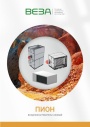
Каталог продукции Веза 2026 - Воздухонагреватели газовые ПИОН. pdf, 6.55 Mb
Каталог газовых воздухонагревателей ПИОН: назначение, конструкция и исполнения, технические характеристики, габаритные размеры, обозначение при заказе. -
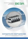
Каталог продукции Веза 2026 - Холодильное оборудование для систем кондиционирования воздуха. pdf, 4.97 Mb
Каталог холодильного оборудования Веза для систем кондиционирования: чиллеры, компрессорно-конденсаторные блоки, фанкойлы и другое оборудование — технические характеристики, габаритные размеры, обозначение при заказе. -
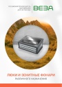
Каталог продукции Веза 2025 - Люки и зенитные фонари различного назначения. pdf, 8.45 Mb
Каталог люков дымоудаления и зенитных фонарей Веза различного назначения: конструкция и исполнения, приводы и автоматика, технические характеристики, габаритные размеры.
Новое в инструкциях
-
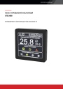
Пульт управления АТБ-2400 для вентиляционных установок Shuft. pdf, 877.42 Kb
Модель АТБ-2400 (производство ООО «АТБ Электроника»). Руководство по эксплуатации настенного пульта: технические характеристики, подключение к контроллеру, главный экран, режимы, уставки, расписание, тревоги, обновление ПО, обслуживание. -
Компактные моноблочные приточные установки Shuft серии CAU W VIM. pdf, 5.89 Mb
Модели: CAU 4000-W VIM, CAU 6000-W VIM. Паспорт (объединённый эксплуатационный документ) установок с водяным нагревателем: описание, массогабаритные показатели, монтаж, схемы электрических соединений, схема обвязки, пусконаладка, обслуживание, неисправности, технические данные. -
Компактные приточные установки Shuft серии AirTube. pdf, 350.53 Kb
Модели: AirTube 160, 200, 250, 315. Паспорт (объединённый эксплуатационный документ): описание устройства, монтаж, подключение электропитания, схемы электрических соединений, обслуживание, поиск и устранение неисправностей, гарантия, технические данные.