

Инструкция на Компактные вентиляционные установки VTS серии VENTUS Compact TOP
Модели: VENTUS COMPACT TOP VVS023c–VVS043c. Руководство по монтажу, эксплуатации и обслуживанию: безопасность, транспортировка и хранение, установка, подключения, автоматика и панели HMI, ввод в эксплуатацию, коды аварий, обслуживание. Документ на английском языке.
Загружаем документ…
Текст инструкции
-
EN
User Manual (Installation, Operation, and Maintenance Manual) Compact air handling units VENTUS COMPACT TOP VVS023c-VVS043c IOMM VENTUS COMPACT - ver. 5.0.9 (06.2026)
-
1 HEALTH AND SAFETY INSTRUCTIONS
Thorough familiarisation with the contents of this manual, as well as installation, commissioning and operation of the air handling unit in accordance with the instructions provided and in compliance with all applicable occupational health and safety regulations, will provide a sound basis for…
-
NSTALLATION, SERVICE WORK AND USE
! BEFORE CARRYING OUT ANY WORK, DISCONNECT THE POWER SUPPLY AND SECURE IT AGAINST UNCONTROLLED START-UP OF THE AIR HANDLING UNIT. THE SERVICE WORK IN PROGRESS MUST BE COMMUNICATED AND CLEARLY MARKED. ! THE UNIT IS FACTORY-CONFIGURED TO START AUTOMATICALLY WHEN THE POWER SUPPLY IS CONNECTED FOR THE…
-
DANGER
ELECTRICAL INSTALLATIONS ! ! ! ! ! ! ! ! ALL ELECTRICAL WORK MUST BE CARRIED OUT BY A LICENSED ELECTRICIAN HOLDING AT LEAST AN E1 QUALIFICATION CERTIFICATE FOR THE OPERATION OF EQUIPMENT, INSTALLATIONS AND NETWORKS, AND A D1 QUALIFICATION CERTIFICATE FOR THE SUPERVISION OF EQUIPMENT, INSTALLATIONS…
-
CAUTION! HOT PARTS
! THE UNIT CONTAINS COMPONENTS WHOSE SURFACE TEMPERATURE MAY BE HIGH, SUCH AS HEAT EXCHANGERS, HEATERS OR THE MOTOR HOUSING. DIRECT CONTACT WITH THESE PARTS MAY RESULT IN BURNS OR OTHER INJURIES. SPECIAL CARE MUST BE TAKEN, APPROPRIATE PROTECTIVE CLOTHING MUST BE WORN, AND SERVICE WORK MAY ONLY BE…
-
RESIDUAL RISK
DURING THE DESIGN AND MANUFACTURING PROCESS OF THE UNITS, THE RISK TO PEOPLE AND PROPERTY HAS BEEN MINIMISED. NEVERTHELESS, A CERTAIN LEVEL OF RISK MAY STILL OCCUR WHICH IS BEYOND THE MANUFACTURER’S CONTROL: • HAZARDS RESULTING FROM INCORRECT INSTALLATION AND ASSEMBLY: o o o o o • HAZARDS RESULTING…
-
FAULTS, REPAIRS, MODIFICATIONS
! ! ! ! IF A FAULT OR INCORRECT OPERATION OF THE UNIT IS DETECTED, THE UNIT MUST BE SWITCHED OFF IMMEDIATELY AND AN AUTHORISED SERVICE PROVIDER MUST BE CONTACTED. ALL REPAIRS MUST BE CARRIED OUT BY THE MANUFACTURER’S AUTHORISED SERVICE PROVIDER, USING ORIGINAL SPARE PARTS. ROUTINE INSPECTIONS…
-
DANGER
EMERGENCY SITUATIONS – FIRE PROCEDURE IN THE EVENT OF A FIRE INVOLVING ELECTRICAL EQUIPMENT: KEEP CALM - DO NOT PANIC, ASSESS THE SITUATION. DISCONNECT THE POWER SUPPLY: • IF POSSIBLE, CUT OFF THE POWER SUPPLY, E.G. BY SWITCHING OFF THE FUSES OR THE MAIN SWITCH. • DO NOT TOUCH THE UNIT OR CABLES…
-
2 GENERAL INFORMATION
Floor-mounted VENTUS COMPACT TOP VVS023c-VVS043c air handling units (AHUs) are designed for indoor installation. The low height of the unit allows it to fit perfectly into standard inter-floor spaces or spaces above suspended ceilings. VENTUS VVS023c-VVS043c air handling units are designed to…
-
OTHER DESIGNATIONS IN THE CONTROL PANEL
AD Air damper FLX.CON Flexible duct connection IN Inlet (supply of e.g. medium) OUT Outlet (return e.g. medium) VENTUS COMPACT units have inspection panels located at the front of the unit. BASE BLOCK DIMENSIONS BY SECTION VVS023c VVS033c VVS043c The units can be manufactured as right- or…
-
The units can be manufactured as right- or left-sided. The orientation of the unit is determined by the direction of airflow in the supply (bottom) path relative to the side of the unit where the inspection panels are located. AIR INLET AND OUTLET DESIGNATION INSPECTION SIDE VIEW - RIGHT-HAND…
-
3 TRANSPORT AND STORAGE
The air handling units are packaged for easy internal transport and storage at the installation site. Upon delivery of the unit, all components must be checked to ensure that no damage has occurred in transit. Detailed instructions for this are included in the table Checklist on receipt. Immediately…
-
! ! ! ! ! ! Any damage caused as a result of incorrect transport, unloading or storage is not covered by the guarantee and any claims submitted for cases of the above nature will not be considered by VTS. VENTUS COMPACT AHUs are supplied in assembled functional sections that need to be connected on…
-
RULES FOR THE TRANSPORT OF AHU SECTIONS
! The air handling units must be transported in the position and in the manner marked on the original manufacturer's packaging. VVS023c VVS033c , VVS043c ! ! Equipment packaging: • should be placed in paved, dry locations protected from precipitation, • should be placed and stored away from areas…
-
! ! ! ! The equipment as well as its components should be: • stored in rooms with the following conditions: o relative humidity: φ < 80 %, at t = (+20) °C, o ambient temperature: (-40) °C < t < (+60) °C. • protected from contact with corrosive (caustic) dusts, gases or vapour, as well as with any…
-
4 THE UNIT INSTALLATION
Transport of the equipment requires lifting equipment at the installation site. Make sure that once the unit is installed, there will be enough space to properly bring the technological and electrical installations to the unit and to carry out maintenance on the unit without any problems. 4.1…
-
4.2 INSTALLATION OF VENTUS COMPACT AIR HANDLING UNIT
! ! ! ! ! ! ! ! The control panel should be located on: • foundation screed, • concrete cast into the floor of the steel foundation frame, • a specially prepared rigid steel structure The foundation, frame or steel structure must be flat and level and should have sufficient strength to match the…
-
VVS023c AHU FOUNDATION LAYOUT
! The dimensions of the base block and additional functions are available in the unit technical data sheet. www.vtsgroup.com IOMM VENTUS COMPACT TOP - ver. 5.0.9 (06.2026) 21
-
VVS033c AHU FOUNDATION LAYOUT
! The dimensions of the base block and additional functions are available in the unit technical data sheet. www.vtsgroup.com IOMM VENTUS COMPACT TOP - ver. 5.0.9 (06.2026) 22
-
VVS043c AHU FOUNDATION LAYOUT
! The dimensions of the base block and additional functions are available in the unit technical data sheet. www.vtsgroup.com IOMM VENTUS COMPACT TOP - ver. 5.0.9 (06.2026) 23
-
FIXING OF THE FRAME/FOOTPLATE TO THE GROUND ! The frame should be fixed through the extreme holes in the feet/frame. ! ! ! ! ! All profiles of the panel frame must be supported. Use M10 screws or dowels to secure the frames to the foundation. Frame deflection of 1mm/1m must not be exceeded The…
-
4.3 CONNECTING AIR DUCTS
INSTALLATION OF AIR DUCTS Air ducts should be connected to the air handling unit with flexible connections (optional equipment) that dampen unit vibrations and compensate for the misalignment of duct and air handling unit outputs. Flexible connections are fitted with sealed flanges. Flexible flanges…
-
4.4 REQUIREMENTS FOR EQUIPMENT TO BE INSTALLED ON THE
SITE BASIC CONDITIONS FOR ASSEMBLY ON SITE - DELIVERY IN SECTIONS Section connection is outside the standard VTS offer. It is possible to purchase an additional option of section connection by an Authorised VTS Service. Assembly may take place at ambient temperatures which allow all technical…
-
4.5 CONNECTING BASE BLOCK SECTIONS
BASE BLOCK ASSEMBLY RIGHT-HAND A A - air filter section D C B - extract fan section with control cabinet C - heat recovery section with a hexagonal counter-flow heat exchanger and by-pass function B LEFT-HAND D - supply fan section. Optionally, the section is equipped with a water heater. A D C B !…
-
BASE BLOCK ASSEMBLY
C D A www.vtsgroup.com IOMM VENTUS COMPACT TOP - ver. 5.0.9 (06.2026) B 28
-
CONNECTING THE FAN SECTION
The VENTUS COMPACT base configuration with heat recovery is supplied as a wired unit with the Control system connected and configured. Using the supplied connectors (electrical cable, pneumatic cable), connect the fan and air filtration sections to the base section (with heat pump). "+" higher…
-
5 CONNECTION OF EXCHANGERS
5.1 CONNECTION OF WATER HEATERS AND COOLERS ! ! ! ! ! ! ! ! The operation of the water exchanger requires its connection to the heat system process depending on the designed function of this exchanger. Exchangers must be protected against freezing (if there is a risk of this). The connection of…
-
SECURING THE SCREWED CONNECTIONS OF THE WATER EXCHANGER
! ! When assembling the supply system for exchangers equipped with bolted connections, the exchanger connector must be relieved with an additional spanner. WATER HEAT EXCHANGER CONNECTIONS IN THE BASE SECTION ! ` www.vtsgroup.com IOMM VENTUS COMPACT TOP - ver. 5.0.9 (06.2026) 31
-
SUPPLY PRINCIPLE FOR WATER EXCHANGERS ` ! The exchanger's fluid supply and return connections should be configured so that the exchanger operates in countercurrent mode. The co-current mode of operation of the exchanger provides a lower average temperature difference, affecting its operating…
-
5.2 CONNECTION OF DX EXCHANGERS (DIRECT EXPANSION)
! ! ! ! ! ! ! ! ! ! Connection of the DX exchanger must be carried out by a qualified refrigeration fitter in accordance with the rules and regulations in force for freon refrigeration appliances (F-gas qualification). The DX heat exchanger is designed for use with R410A or R32 refrigerant (not…
-
5.3 CONDENSATE DRAINAGE
Moisture can condense on the surfaces of the air coolers and heat recovery exchanger. from the air. The condensed moisture (condensate) flows into the drip tray located below these functions. The installer must connect the drip trays to the drainage system, including the use of traps. Condensate…
-
6 ELECTRICAL CONNECTION TO THE CONTROL
PANEL 6.1 ELECTRICAL CONNECTION Supply and extract units with a hexagonal counter-flow heat recovery exchanger are factorywired and equipped with advanced control and safety automation. The connection box (electrical isolator) for the unit power supply is routed outside the AHU. The isolator is…
-
! ! AHUs without heat recovery require an external power and control switchgear and Control components to be installed, connected and configured on site. See instructions: • "Control gear for Supply and Supply-Exhaust Air Handling Units." / "Control gear for Supply and Supply-Exhaust Air Handling…
-
MOLEX CONNECTING BRACKET EC MOTOR 0,75kW
Colour coding: brown - 230V AC , blue - neutral , green/yellow - earthing green - RS485 TX+/A, yellow - RS485 TX-/B, red - 10V DC output, black - 0-10V DC AIN input, white - GND www.vtsgroup.com IOMM VENTUS COMPACT TOP - ver. 5.0.9 (06.2026) 37
-
7 ELECTRIC HEATER
7.1 GENERAL INFORMATION The electric heater can be an optional accessory (separate section) or built into the base block of the air handling unit (VVS021c, VVS030c). If the heater is built into the base block, the heater is connected at the factory to the main supply point of the air handling unit.…
-
The electric heater is an optional accessory and consists of heating elements (heaters), connection
terminal, control Control (SCCR) and over-temperature protection. The heaters are Cr-Ni-Fe heating wires of 6kW/400V. They are connected in heating slices (heating sections). The heater can consist of: 1, 2 or 3 heating slices. Electric heaters can be supplied in two power variants - low power…
-
7.2 HEATER POWER CONNECTION AND CURRENT PROTECTION
! ! ! ! The power supply connection must be made using a separate switchboard, which is not supplied by VTS. The heater connection should be made in such a way that the heater cannot be switched on when the fan is not switched on - this is ensured by factory-fitted, series-connected safety devices…
-
Designation Description Connection Comments 1 relays / contactors - 2 heater terminals factory factory 3 heaters factory 4 pressure switch factory / installer 5 signal terminals - alarm on site / installer the connection of the pressure switch tubes is made by the user - 6 power terminals 1f on site…
-
CONNECTION OF ELECTRIC HEATER WITH 4X18KW SWITCHBOARD
P. DESCRIPTION CONNECTION COMMENTS 1 relays / contactors - 2 heater terminals factory factory 3 heaters factory 4 pressure switch factory / installer 5 signal terminals - alarm on site / installer the connection of the pressure switch tubes is made by the user - 6 power terminals 1f on site /…
-
7.3 THERMAL CUT-OUT (THERMIC)
The functionality of the thermostat is based on the properties of the bimetallic element - it causes the contacts of the heater control circuit to open when the air temperature near the thermostat is 65°C. After an emergency shutdown, the heater automatically switches on when the air temperature…
-
7.4 DIFFERENTIAL PRESSURE SWITCH
The differential pressure switch is another safety element, in addition to the thermostat, which prevents the heater from operating under unallowable conditions. It prevents the heater from switching on if the pressure generated by the fan units on the supply side of the air handling unit is…
-
DIFFERENTIAL PRESSURE SWITCH - CHARACTERISTICS
DIFFERENTIAL PRESSURE SWITCH CONNECT Function Construction NOTES protection of the heater against overheating (control of pressure difference between supply air and atmospheric pressure) • plastic housing, • two screw terminals, • diaphragm connected to mechanical module Rated operating voltage…
-
8 PLUG&PLAY CONTROL COMPONENTS
The VENTUS COMPACT base unit with heat recovery (counter-flow hexagonal exchanger or rotary exchanger), fans and air filters is supplied as a pre-wired unit with the configured Control system connected. The Control system is based on the factory-programmed and built-in uPC3 controller. Peripheral…
-
8.1 STANDARD EQUIPMENT WITH FACTORY-FITTED CONTROL
ELEMENTS STANDARD CONTROL COMPONENTS - ASSEMBLY AND CONNECTION AT THE FACTORY Designation Name uPC3 controller Terminal 1 (T1) Location Differential pressure sensor Control switchgear Connection terminal for peripheral Control components Control switchgear (according to the diagram) Return air from…
-
8.2 CONNECTION TERMINAL 1 (T1)
Terminal 1 (T1) is connected at the factory to the uPC3 controller and is a dedicated terminal for the connection of peripheral Control elements that exist outside the base unit of the unit and therefore could not be connected at the factory. Additional Control elements outside the VTS range can…
-
8.3 CABLE STANDARDS
TYPE WIRED WIRING [mm] Fire alarm relay [2] 2x0,75 Multifunction switch [2] 2x0,75 Optional multifunction switch [2] 2x0,75 Supply air temperature sensor [1] 2x0,75 Room/extract air temperature sensor [1] 2x0,75 Return water temperature sensor for water heater [1] 2x0,75 Electric heater (HE) alarm…
-
8.4 ANALOGUE INPUTS (NTC10K)
ANALOGUE INPUTS (NTC10K) B1 Duct temperature sensor supply air B2* Temperature sensor - exhaust air B2/6 Duct sensor behind the preheater B3** Temperature sensor - outside air B5*** • • • Touchscreen water heater temperature sensor. B2* - Exhaust air temperature sensor which is factory fitted at the…
-
SUPPLY AIR TEMPERATURE SENSOR B1 SUPPLY AIR TEMPERATURE SENSOR B1 The sensor should be placed in the supply air duct after the last function that changes the air temperature in a stabilised and homogeneous air stream with a uniform temperature distribution. The sensor should be placed in the supply…
-
TOUCHSCREEN WATER HEATER TEMPERATURE SENSOR B5 TOUCHSCREEN WATER HEATER TEMPERATURE SENSOR B5 www.vtsgroup.com IOMM VENTUS COMPACT TOP - ver. 5.0.9 (06.2026) 52
-
8.5 DIGITAL INPUTS
DIGITAL INPUTS DI1 Fire alarm DI2* Heater alarm (freezing) Radiator alarm DI3 Humidifier alarm DI4 Cold source alarm DI5 Remote Programmable external input (enabling the panel or overriding the selected operating mode) DI2* - Heater alarm (freezing). If there is no water heater and an electric…
-
FIRE ALARM SIGNAL DI1 FIRE ALARM SIGNAL DI1 8.5.2 WATER HEATER FROST SENSOR DI2 WATER HEATER FROST SENSOR DI2 www.vtsgroup.com IOMM VENTUS COMPACT TOP - ver. 5.0.9 (06.2026) 54
-
COLD SOURCE ALARM DI3 COLD SOURCE ALARM www.vtsgroup.com IOMM VENTUS COMPACT TOP - ver. 5.0.9 (06.2026) 55
-
ANALOGUE OUTPUTS (NTC10K) AO1* Heat recovery AO2 Air mixing AO3 Humidification or secondary heater AO4 Pre- or post-heater Y1** Y3*** • • • Main heater or secondary heater behind DX-H or mixing chamber Aftercooler or afterheater after DX-H or mixing chamber A01* - factory connection outside terminal…
-
VALVE ACTUATOR OF THE WATER MAIN HEATER AND CONTROL SIGNAL OF THE ELECTRIC MAIN HEATER Y1 MAIN WATER HEATER Y1 For the water heater, the control is connected to the valve actuator 8.6.2 VALVE ACTUATOR FOR WATER PRE- OR RE-HEATER AFTER DX-H Y1 WATER PRE- OR POST-HEATER BEHIND DX-H Y1 For the water…
-
DIGITAL OUTPUTS (24V DC) D01 Main heater (or secondary heater if DX-H) D02 Air inlet and outlet passes D03 Radiator stage 1 or DX-H signal D04 Stage 2 cooler or stage 1 DX-H or humidifier or glycol recovery or redundant dampers D04 Heater stage 2 or DXH stage 2 D06 Pre-heater or secondary heater or…
-
8.8 CONNECTION OF CONDENSING UNIT SIGNALS
DX EXCHANGER (0-10V CONTROL) DX EXCHANGER (ON-OFF CONTROL) www.vtsgroup.com IOMM VENTUS COMPACT TOP - ver. 5.0.9 (06.2026) 59
-
8.9 CONNECTION OF THREE-WAY VALVES
HEATER VALVE CONNECTION COOLER VALVE CONNECTION www.vtsgroup.com IOMM VENTUS COMPACT TOP - ver. 5.0.9 (06.2026) 60
-
8.10 CONNECTION OF AIR DAMPER ACTUATORS
0-10 V/S actuators with capacitor 0-10 V/S actuators without capacitor Actuator ON-OFF 8.11 MODBUS RTU RS485 COMMUNICATION MODBUS RTU RS485 COMMUNICATION Humidity sensor air supply Humidity sensor - room (extract air)* HMI Basic CO2 sensor www.vtsgroup.com IOMM VENTUS COMPACT TOP - ver. 5.0.9…
-
Factory assembly 8.12 CONNECTION OF OPERATOR PANELS 8.12.1 HMI ADVANCED HMI ADVANCED www.vtsgroup.com IOMM VENTUS COMPACT TOP - ver. 5.0.9 (06.2026) 62
-
8.12.2 HMI BASIC (2HY)
HMI BASIC 2HY HMI connections are powered by 110-230V AC mains voltage. To ensure correct operation, separate power and control cables must be used, not exceeding the recommended length of 500m. The following cable types are recommended: • supply: H05VV-F 2x1 mm2 • communication: FTP 3x0.22 mm2…
-
8.12.3 WebHMI and VMS
VENTUS MANAGEMENT SYSTEM VMS - Ventus Management System visualisation of panel operation with WebHMI function http:/192.168.1.111 service service A fixed address is required to connect the controller IP: 192.168.1.xxx, where xxx is different from 111. Subnet mask 255.255.255.0 www.vtsgroup.com IOMM…
-
8.12.4 mHMI APPLICATION - BLUETOOTH DEVICE PAIRING
See chapter "BLUETOOTH MODULE AND mHMI APPLICATION". www.vtsgroup.com IOMM VENTUS COMPACT TOP - ver. 5.0.9 (06.2026) 65
-
9 FIRST START-UP
9.1 PREPARATION FOR THE FIRST START-UP ! ! ! ! ! ! THE UNIT IS FACTORY-CONFIGURED TO START AUTOMATICALLY WHEN THE POWER SUPPLY IS CONNECTED FOR THE FIRST TIME. Before proceeding with the activities leading to the first start-up, read the operating instructions for the operator panels. The air…
-
Grounding system
Check that earthing cables are in place, connecting the control systems to the ventilation ducts. Condensate system Check that the condensate traps and drainage systems from the condensate gutter are fitted. Control peripherals Check the connections of the peripheral devices (T1 terminal) - as the…
-
POWER CONFIGURATION OF OPTIONAL ELECTRIC HEATERS ! ! If the unit is equipped with an electric heater, the heater's heating sections must be configured. CONFIGURATION OF ELECTRIC HEATER POWER STAGES Read the power distribution from the diagram or technical data sheet. For example, we have: 0-10V DC =…
-
9.2 FIRST START-UP
9.2.1 FACTORY PARAMETERS ! ! ! ! ! The control unit, which is supplied as a Plug&Play standard, has its Control configured according to the parameters and criteria specified in the unit's selection sheet. No additional site configurations are required in order to run the control unit in Plug&Play in…
-
BASIC FACTORY CONFIGURATION - OPERATING PROFILES (MODE)
WORK PROFILES Comfort** Economic StandBy Comfort** Ekono StandBy PARAMETER Temperature T °C Relative humidity - RH RH* % Air quality - CO2 content ppm ppm Supply capacity V *S % m3/h Exhaust capacity V *E % m3/h • • • • Work profiles: Comfort, Economic require the time and date of their validity to…
-
COMMISSIONING PLUG&PLAY CONTROL PANEL COMMISSIONING Switch on the power supply to the control panel Physical Virtual Enable HMI Advanced* http:/192.168.1.111 Change in device status (operating mode) OFF Switch to OFF mode to any other mode (work profile) as preferred* ON ECO OPTI COMF StBy AUTO…
-
HMI ADVANCED HMI ADVANCED - NAVIGATION A 1 "Alarm" button (calling up active and archived alarms, clearing alarms). When an alarm is active, the button is illuminated in red. Button for changing the operating modes (OFF/Auto/Low/Econo/Comfort). Confirmation by pressing ENTER. ESC button (return to…
-
HMI ADVANCED NAVIGATION cont
Current date and time. 7 Current work profile 8 9 Current fan controls Air handling unit status (fans running/stopping, heating/cooling, activation of recovery Current leading temperature value Lead temperature setpoint Operating status icon: Opening/closing the throttles Fan operation Heating…
-
HMI BASIC 2HY HMI BASIC 2 HY The HMI Basic 2 HY is a basic control panel designed to operate VTS air handling units equipped with the uPC3 controller. The functions realised are: • starting and stopping the control panel, • operating mode selection, • the possibility to view and change the…
-
changing parameter values
! ! ! ! ! ! In the absence of communication with the controller, the HMI Basic 2 HY will only display the current room temperature. Activation of the panel in the air handling unit controller settings The panel is intended for air handling units equipped with the uPC3 controller with software…
-
• the set temperature,
• humidity, • CO2 levels, • supply fan speeds (S), • exhaust fan speeds (E). Access to individual settings depends on the configuration of the control panel and its actual components. Changes are made using approvals by means of Exit to home screen automatically after a moment of inactivity or by…
-
• T - not used
! Access to individual settings depends on the configuration of the control panel and its actual components. Output ! Exit to the home screen is automatic after a moment of inactivity or by pressing . ALARM HANDLING The MI Basic 2 HY allows active alarms to be viewed and cleared. If an alarm is…
-
D) Permissible operating temperature Destination for indoor mounting (IP20) Assembly in a standard Ø60 installation box on a mounting bracket Mass 150g 86 x 86 x 17 mm 0⁰C 50⁰C ! ! ! ! ! ! In the absence of communication with the controller, the HMI Basic 2 HY will only display the current room…
-
BLUETOOTH MODULE AND mHMI APPLICATION The Bluetooth module is designed for low-power Bluetooth V5.0 connectivity to mobile devices. The module transmits an RS485 serial transmission signal [Modbus RTU] from the master controller to the mobile device using a Bluetooth connection, thus eliminating the…
-
REQUIREMENTS
• • • Control software uPC3 from 1.0.26 Smartphone with systems from versions: Android 9, iOS 11 Assignment of rights and activation: o location (linked to a Bluetooth connection) o bluetooth connections BT MODULE SUPPORT The unit allows other units to connect via the broadcast system. The default…
-
CONFIGURATION OF THE UPC3 CONTROLLER - mHMI and HMI ADVANCED
• • • "Address" - address of the controller used for external protocol communication "Speed" - speed (baudrate) of the external controller protocol "External port of the pLan controller" - type of protocol used by the controller's pLan port (RJ11 socket) [for mHMI, the value of the pLan port…
-
ACTIVATION OF THE BLUETOOTH MODULE
Remove the control panel junction box housing. The BT module should be plugged into the T1 terminal. If the BT module was ordered separately, plug it into the socket shown in the figure. Find the button on the bluetooth (BT) module and press it until the LED starts flashing. This indicates that the…
-
ADDING A DEVICE
! If a Plug&Play VENTUS COMPACT device has been ordered together with an mHMI module, it already has a factory-programmed number in the application. ACTIVATION OF THE DEVICE Select a paired device Then, in the Menu, select one of the operating modes Operation Mode "On": • Eco • Comfort • Standby •…
-
OVERVIEW OF SELECTED ASPECTS OF THE mHMI APPLICATION
• The app includes a tutorial for pairing and connecting the device. PANEL OVERVIEW The PBX View contains the basic operating parameters of the PBX : • outside air temperature, • indoor air temperature, • the set air temperature (of the lead sensor), • degree of fan speed control, • state of the…
-
OPERATING MODE PARAMETERS
The Mode window presents the basic parameters relating to a particular mode and allows them to be edited quickly. WORK SCHEDULE - CALENDAR When the Schedule icon is selected, there is an option: • to edit the days of switching on/off the control panel, • to establish hourly intervals for the…
-
ALARMS
The list of alarms is visible under the icon Alarms can be opened in one of two views: • Current alerts, • Historic alarms. The list of historical alarms shows a preview of alarms that are not currently active. If a situation occurs that affects to activate an alarm, it will be shown in the list of…
-
FUNCTION SETTINGS - ADVANCED FUNCTIONS
FUNCTION SETTINGS - this menu section gives you the possibility to view and edit the operating parameters of the associated control panel. In addition, you can access the control of individual inputs and outputs located on the control panel controller and also on the expansion board. TEMPERATURE The…
-
FUNCTION SETTINGS - ADVANCED FEATURES (cont'd)
I/O. - Configurable digital and analogue inputs and outputs as well as ModBus signals. and analogue inputs and outputs as well as ModBus signals. The inputs and outputs have been labelled with the functions they are assigned, e.g. DI1 - Fire alarm - is the digital input responsible for the fire…
-
MONITORING
MONITORING The user can define a quick-view list of selected parameters. To use this functionality, the user must save the selected parameters in the MONITORING section APPLICATION SETTINGS APPLICATION SETTINGS General settings section, which is not related to operating parameters. Here it is…
-
OPERATING MODES OF THE CONTROL PANEL OPERATING MODES OF THE CONTROL PANEL OFF Air handling unit switched off - fans stopped, air dampers and control valves closed all sensors and measuring devices remain active - to protect the unit from damage, e.g. fire alarm, anti-FROST protection. AUTO Panel…
-
VERIFICATION OF OPERATION DURING INITIAL START-UP During the initial start-up, it is recommended that the steps listed below be carried out. CHECKING THE OPERATION OF THE FANS Check that the fans do not make excessive noise (make sure that the impeller does not rub against the hopper and that there…
-
CHECK OF SENSOR READINGS
• check if the readings from temperature, pressure, CO2 and humidity sensors are correct (at the beginning, when the air handling unit is powered but not operating, temperatures sent to the controller from temperature sensors should oscillate within the ambient temperature range of the air handling…
-
CHECKING THE OPERATION OF THE WATER HEATER VALVE ACTUATORS
Check that the heater valve actuator responds to the control signal - manually actuate the valve from the controller's service menu and observe whether it causes the valve to open/close accordingly. To do this, set parameter D to ON and parameter A to the desired percentage in the corresponding…
-
THE MOST COMMON ADAPTATIONS TO THE NEEDS OF THE FACILITY FUNCTION SCOPE OF THE CHANGES SCREEN WHEN TO CHANGE MAIN HEATER A07 PID unstable temperature control DXH MAINTAIN A11 compressor switch-on thresholds unstable temperature control SECONDARY HEATER A12 PID unstable temperature control PRE-HEATER…
-
FUNCTION
SCREEN SCOPE OF THE CHANGES NOTES PRE-HEATER A29 supply air heating support object sensitive to low air temperature AHU A21 next min. air temp. and switch-off delay. object sensitive to low air temperature DX MAINTAIN B04 compressor runtime setting VENTILATORS C11 fire settings matching of object…
-
FUNCTION
PRE-HEATER SECONDARY HEATER TRANS. VENT. REDUN. PROCESSED. PRESS. FILTERS ADDITIONAL FILTERS. ADDITIONAL FILTERS. SCREEN SCOPE OF THE CHANGES G11 logic of work permit exit matching the properties of the heater G11 logic of work permit exit matching the properties of the humidifier G11 logic of work…
-
10 MAINTENANCE
10.1 MAINTENANCE ! ! ! ! ! ! Personnel responsible for operating the control panel should read the documentation before starting any operations and maintenance activities. In the absence of such personnel with the necessary skills and competence, periodic inspections should be carried out by…
-
• • • • Active water heaters should be equipped with anti-FROST systems. Optionally, a non-freezing heating medium (e.g. glycol solution) can be used in winter. If the heating medium is cut off or the air handling unit is at a standstill, and if the air temperature is likely to fall below + 5°C, the…
-
ELECTRIC HEATER
• • • The electric heater battery consists of bare heating coils. During operation of the air handling unit, when the heater is switched off, dust may settle on the heating coils. When the heater is restarted, heavy contamination of the surface of the heater can generate unpleasant burning dust…
-
HEAT RECUPERATOR (COUNTER-FLOW, HEXAGONAL, CROSS-FLOW)
Maintenance of the exchanger is limited to checking its technical condition and the degree of fouling of the aluminium plates, once every 4 months. The accumulation of dirt in heat exchangers is often limited to the first 50 mm in the exchanger. Before cleaning, the adjacent sections must be…
-
dust deposition on the fan impeller blades,
Wrong direction of fan rotation. If the centrifugal fan rotates in the wrong direction, the air flow causes significantly harmful effects. When performing maintenance on the fan, check that: o the rotor turns freely, - the rotor is properly balanced, o the rotor is securely mounted on the journal, o…
-
10.2 CONSUMABLES
-
IOMM VENTUS COMPACT TOP - ver. 5.0.9 (06.2026)
-
VVS030c
-
10.3 ELECTRIC HEATER DIAGRAM
10.3.1 LOW POWER – 6KW – VVS023c, VVS033c c www.vtsgroup.com IOMM VENTUS COMPACT TOP - ver. 5.0.9 (06.2026) 105
-
10.3.2 LOW POWER – 6KW – VVS043c
www.vtsgroup.com IOMM VENTUS COMPACT TOP - ver. 5.0.9 (06.2026) 106
-
www.vtsgroup.com IOMM VENTUS COMPACT TOP - ver. 5.0.9 (06.2026) 107
-
10.3.4 HIGH POWER – 24KW – VVS043c
www.vtsgroup.com IOMM VENTUS COMPACT TOP - ver. 5.0.9 (06.2026) 108
-
www.vtsgroup.com IOMM VENTUS COMPACT TOP - ver. 5.0.9 (06.2026) 109
-
10.3.6 HIGH POWER – 48KW – VVS043c
www.vtsgroup.com IOMM VENTUS COMPACT TOP - ver. 5.0.9 (06.2026) 110
-
10.3.7 HIGH POWER – 72KW – VVS043c
www.vtsgroup.com IOMM VENTUS COMPACT TOP - ver. 5.0.9 (06.2026) 111
-
10.3.8 HIGH POWER – 54KW – VVS033c
www.vtsgroup.com IOMM VENTUS COMPACT TOP - ver. 5.0.9 (06.2026) 112
-
10.4 UNIT WIRING DIAGRAM
10.4.1 PLUG&PLAY HEX (1/4) www.vtsgroup.com IOMM VENTUS COMPACT TOP - ver. 5.0.9 (06.2026) 113
-
10.4.2 PLUG&PLAY HEX (2/4)
www.vtsgroup.com IOMM VENTUS COMPACT TOP - ver. 5.0.9 (06.2026) 114
-
PLUG&PLAY HEX (3/4) www.vtsgroup.com IOMM VENTUS COMPACT TOP - ver. 5.0.9 (06.2026) 115
-
10.4.4 PLUG&PLAY HEX (4/4)
www.vtsgroup.com IOMM VENTUS COMPACT TOP - ver. 5.0.9 (06.2026) 116
-
IOMM VENTUS COMPACT TOP - ver. 5.0.9 (06.2026)
-
11 SUPPLEMENTARY INFORMATION
11.1 TECHNICAL INFORMATION FOR REGULATION (EU) N327/2011 IMPLEMENTING DIRECTIVE 2009/125/EC. Model: 1. 2. 3. 4. 5. 6. 7. 8. 9. 10. 11. 19/0,16 EC 60,2 A Static 62 Yes 2018 VTS, Poland 1-2-0294-1750 169W, 540m3/h, 450Pa 4030RPM 1 12. • 13. 14. 22/0,37 EC 60,8% A Static 62 Yes 2018 VTS, Poland…
-
SR-FS FANS
-
11.2 ASSOCIATED INSTRUCTIONS
! ! Refer to the detailed instructions and make the connections and configurations according to the documentation available at www.vtsgroup.com and the instructions supplied with the equipment. In particular, you should familiarise yourself with: • Installation, Operation and Maintenance Manual…
-
11.4 DISMANTLING AND DISPOSAL OF AHU
! ! ! ! ! The dismantling of the appliance should be carried out and/or supervised by suitably qualified personnel with the appropriate level of knowledge and authority. A certified waste disposal organisation in your region should be contacted. Confirm how to prepare and segregate materials…
-
11.5 NOTES
Routine checks, carried out by qualified technical personnel or service personnel authorised by VTS, guarantee long-term, reliable and trouble-free operation of the equipment. Our service staff is available at all times to provides support for commissioning, maintenance and in the event of any…
-
DEKLARACJA ZGODNOŚCI UE / EU DECLARATION OF CONFORMITY My Producent: /The Manufacturer: VTS Sp. z o.o. ul. Aleja Grunwaldzka 472A 80e-309 Gdańsk, Poland Strona internetowa / Website: www.vtsgroup.com Modele / Models: VENTUS COMACT VVS021c, VVS030c, VVS040c, VVS055c, VVS075c, VVS100c, VVS120c…
Схемы, таблицы и рисунки — в просмотре документа выше. Клик по номеру страницы открывает её в просмотре.
Новое в каталогах
-

Каталог продукции Веза - Клапан противопожарный универсальный КПУ-3. pdf, 990.15 Kb
Каталог универсального противопожарного клапана КПУ-3: назначение, конструкция, приводы, технические характеристики, габаритные размеры, обозначение при заказе. -
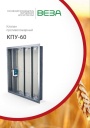
Каталог продукции Веза - Клапан противопожарный КПУ-60. pdf, 839.50 Kb
Каталог противопожарного клапана КПУ-60: назначение, конструкция, приводы, технические характеристики, габаритные размеры, обозначение при заказе. -
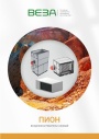
Каталог продукции Веза 2026 - Воздухонагреватели газовые ПИОН. pdf, 6.55 Mb
Каталог газовых воздухонагревателей ПИОН: назначение, конструкция и исполнения, технические характеристики, габаритные размеры, обозначение при заказе.
Новое в инструкциях
-
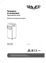
Мобильные кондиционеры Shuft серии Frigo. pdf, 11.28 Mb
Модели: SFPAC-07 KF/N6, SFPAC-09 KF/N6. Руководство по эксплуатации: устройство и технические характеристики, управление кондиционером, монтаж, устранение неисправностей, самодиагностика, транспортировка и хранение, гарантийный талон. -
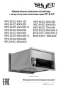
Прямоугольные канальные вентиляторы Shuft серии RF-B EC. pdf, 7.50 Mb
Модели: RFE-B EC 300x150 … 600x350, RFD-B EC 600x300 … 1000x500. Паспорт (объединённый эксплуатационный документ): описание, массогабаритные показатели, монтаж, подключение электропитания, схема электрического соединения, пуск, обслуживание, неисправности, гарантийные обязательства, технические данные. -
Крышные вентиляторы Shuft серии RMV VIM. pdf, 4.41 Mb
Модели: RMVE 190/300-2 … 450/670-4, RMVD 311/440-4 … 630/950-4 VIM. Паспорт (объединённый эксплуатационный документ): описание, массогабаритные показатели, монтаж, схемы электрических соединений, пуск, обслуживание, гарантийные обязательства, технические данные.