

Инструкция на Кондиционеры серии LM
Кондиционеры серии LM-2421C2L, LM-3022C3L. Инструкция по монтажу и эксплуатации.
Смотрите также: Инструкция по монтажу и эксплуатации →
Загружаем документ…
Текст инструкции
-
Multi Type Room Air Conditioner
-
Functions
Indoor Unit Remote Controller Operation ON/OFF Operation ON/OFF by Remote controller Sensing the Room Temperature • Room temperature sensor (THERMISTOR) Operation Mode Selection Room temperature control Cooling Operation Mode ( ) Soft Dry Operation Mode ( ) • Maintains the room temperature in…
-
Product Specifications(Cooling Only)
-
2. LM-3022C3L
-
Dimensions
-
2. Outdoor Unit
-
2-2. LM-3022C3L
-
Refrigeration Cycle Diagram
1. LM-2421C2L ø12.7 ø12.7 COMP HEAT EXCHANGER HEAT EXCHANGER 3-WAY Valve (A Unit) (B Unit) ø6.35 ø6.35 Gas Liquid Max. piping length (m) 1/2" 1/4" 10~15 Pipe Size (Diameter : inch) Max. piping elevation (m) 5~7 -9- ex) Solenoid Valve Capillary Cooling
-
2. LM-3022C3CL
ø12.7 COMP ACCUMUIATOR ø12.7 ø12.7 HEAT EXCHANGER HEAT EXCHANGER 3-WAY Valve (A Unit) (B Unit) (C Unit) ø6.35 ø6.35 ø6.35 2-WAY Valve Gas Liquid Max. piping length (m) 1/2" 1/4" 10~15 Pipe Size (Diameter : inch) Max. piping elevation (m) 5~7 - 10 - ex) Solenoid Valve Capillary Cooling
-
Wiring Diagram(Cooling Only)
-
Operation Details
1. MAIN UNIT FUNCTION • DISPLAY Operation Indicator • On while in appliance operation, off while in appliance pause • Flashing while in disconnection or short in Thermistor (3 sec off / 0.5 sec on) Soft Dry Indicator • On while in healthy dehumidification mode, off when healthy dehumdification is…
-
■ Auto Restarting Operation
• When the power is restored after a sudden power failure while in appliance operation, the mode before the power failure is kept on the memory and the appliance automatically operates in the mode on the memory. • The slide switch on the main unit of the appliance should be on the Auto Restarting…
-
Display Function
Cooling Model Operation Indicator • Operation Timer Indicator • Timer Mode Soft Dry Indicator • Soft Dry Mode OUT DOOR Outdoor Unit Operation • Outdoor Unit Operating or not Self-diagnosis Function ■ Error Indicator • The function is to self-diagnoisis airconditioner and express the troubles…
-
Installation
(1) Installation of Indoor, Outdoor unit 1) Selection of the best location Front 1. Indoor unit • There should not be any heat source or steam near the unit. • There should not be any obstacles to prevent the air circulation. • A place where air circulation in the room will be good. • A place where…
-
2) Indoor Unit Installation
The mounting wall should be strong and solid enough to protect it from the vibration. Installation Plate 1. Mount the installation plate on the wall with four Type "A" screws. (If mounting the unit on the concrete wall, consider using anchor bolts.) • Always mount the Installation plate horizontally…
-
(2) Piping and Drainage of Indoor Unit
1) Preparation of pipings Pipe cutter 1. Cut the pipes and the cable. • Use the accessory piping kit or the pipes purchased locally. • Measure the distance between the indoor and the outdoor unit. • Cut the pipes a little longer than the measured distance. • Cut the cable 1.5m longer than the length…
-
2) Connection of Pipings
1. Remove the installation plate • Pull the two '∆' marked portion of bottom of the chassis and pull the installation plate out of chassis. Installation plate Pull 2. Route the drain hose and the indoor tubing. Pull For right rear piping 3. Insert the pipings, the connecting cables and the drain…
-
5. Bend the tubing as shown in the figure and
bind the pipings, the connecting cables and the drain hose altogether. • Make a small loop for easy connection later. 6. Tape the tubing, drain hose and the connecting cable. Be sure that drain hose locates at the lowest side of the bundle. Locating at the upper side can be a reason that drain water…
-
For left rear pipings
Drain hose 3. Route the indoor tubing with the drain hose to the piping hole as desired position. Tubing holder • To remove the holder, press the bottom of the chassis near the holder upwards and the tab is clear of its hole. • Turn it clockwise approx. 90° and remove it. 4. Insert the pipings and…
-
7. Indoor unit installation
• Hook the indoor unit onto the upper position of installation plate. (Engage the two hooks of the rear top of the indoor unit with the upper edge of the installation plate.) Ensure the hooks are properly seated on the installation plate by moving it in left and right. Connecting cable Drain hose…
-
10. Set the pipings and the connecting cable to
the back of the chassis with the tubing holder. • Hook the edge of tubing holder to tap on chassis and push the bottom of tubing holder to be engaged in the bottom of chassis. 11. Indoor unit installation. • Hook the indoor unit onto the upper portion of installation plate. (Engage the two hooks of…
-
(3) Connecting Pipings and the cable to Outdoor unit
1) Connecting the pipings to the Outdoor unit 1. Align the center of the pipings and sufficiently tighten the flare nut with fingers. 2. Finally, tighten the flare nut with torque wrench until the wrench clicks. • When tightening the flare nut with torque wrench, ensure the direction for tightening…
-
2) Connection of the cable
Terminal block 1. Remove the cover control from the unit by loosening the screw. Connect the wires to the terminals on the control board individually as the following. Over 5mm Holder for power supply cord • LM-2421C2L 1(L) 2(N) Terminal on the OUTDOOR UNIT 3 1(L) 2(N) 3 1(L) Cover control…
-
(4) Checking the Drainage and Pipe forming
1) Checking the Drainage 1. Remove the Grille from the cabinet • Set the up-and-down air direction louver to open position(horizontally) by finger pressure. • Remove the securing screws. • To remove the Grille, pull lower the left and right side of the grille toward you (slightly tilted) and lift it…
-
2) Connect the cable to the indoor unit
1. Connect the wires to the terminals on the control board individually according to the outdoor unit connection. • Ensure that the color of the wires of outdoor unit and the terminal No. are the same as those of indoor unit respectively. • LM-2421C2L 1(L) 2(N) Terminal on the OUTDOOR UNIT 3 1(L)…
-
3) Form the pipings
1. Wrap the connecting portion of indoor unit with the Insulation material and secure it with two Plastic Bands(for the right pipings). • If you want to connect an additional drain hose, the end of the drain-outlet should keep distance from the ground.(Do not dip it into water, and fix it on the…
-
(5) Air Purging of the Pipings and indoor unit
The air which contains moisture remaining in the is refrigeration cycle may cause a malfunction on the compressor. 1. Confirm that both the liquid side valve and the gas side valve are set to the closed position. 2. After connecting the piping, check the joints for gas leakage with gas leak…
-
(6) Maximum Length of Pipe and Freon Extra Charge
Charge amount per 1m STANDARD LENGTH(m) Model Maximum Length & Height(m) A B Charge am't(g) per 1m LM-2421C2L 7.5 LM-3022C3L 7.5 B(Length) INDOOR UNIT A(Height) OUTDOOR UNIT INDOOR UNIT INDOOR UNIT Preventive function of cable mis-connection This product has a preventive function of cable…
-
(7) Test running
1) Connection of power supply 1. Connect the power supply cord to the independent power supply. 2. Prepare the remote control. • Insert two batteries provided. Remove the battery cover from the remote controller. • Slide the cover according to the arrow direction. Insert the two batteries. (Two…
-
Operation
Name and Function-Remote Control Remote Control Signal trasmitter 1 OPERATION DISPLAY Transmits the signals to the room air conditioner. Displays the operation conditions. 2 CHAOS SWING BUTTON Used to stop or start louver movement and set the desired up/down airflow direction. TEMP. 1 OFF TIME 3…
-
Disassembly of the parts (Indoor unit)
Warning : Disconnect the unit from power supply before making any checks. Be sure the power switch is set to “OFF”. To remove the Grille from the Chassis. • Set the up-and-down air discharge louver to open position (horizontally) by finger pressure. • Remove the securing screws • To remove the…
-
2. To remove the Control Box
• Remove securing screws. • Pull the control box out from the chassis carefully. 3. To remove the Discharge Grille. • Pull the discharge grille out from the chassis carefully. 4. To remove the Evaporator. • Remove screws securing the evaporator and the holder eva. • Unhook the tab on the right…
-
2-way, 3-way Valve
2-way Valve (Liguid Side) Hexagonal wrench (4mm) Flare nut 3-way Valve (Gas Side) Valve cap Open position Flare nut Closed position Open position Closed position Pin To piping connection To piping connection Service Service port cap port To outdoor unit To outdoor unit Works Shaft position Shaft…
-
(1) Pumping down
Liquid side Indoor unit 2-Way valve Outdoor unit Close Gas side 3-Way valve Open manifold gauge Low-handle (CLOSE) Hi- handle (CLOSE) • Procedure 6. Operate the air conditioner at the cooling cycle and stop it when the gauge indicates 1kg/cm g. 1. Confirm that both the gas side and liquid side…
-
(2) Evacuation
(All amount of refrigerant leaked) Indoor unit Liquid side 2-Way valve Close Outdoor unit Gas side 3-Way valve Open manifold gauge Vacuum pump Lowhandle (OPEN) Hi- handle (CLOSE) • Procedure 1. Confirm that both the liguid side valve and gas side valve are set to the opened position. 2. Connect the…
-
(3) Gas Charging
(After Evacuation) Liquid side Indoor unit 2-Way valve Close Outdoor unit Gas side 3-Way valve Charging cylinder Open manifold gauge Low-handle Check valve (OPEN) Hi- handle (CLOSE) • Procedure 1. Connect the gauge to the charging cylinder. - Connect the charge hose which you disconnected from the…
-
Cycle Troubleshooting Guide
Trouble analysis • Check temperature difference between intake and discharge air and operating current. Temp. difference Current : approx. 0°C : less than 80% of rated current All amount of refrigerant leaked out. Check refrigeration cycle. Temp. difference Current : approx. 8°C : less than 80% of…
-
When product is operating normally, but there is no cool air from all three indoor unit
Check as follows.(LM-3022C3L) No cool air from all three indoor unit Compressor is operating normally. Outdoor unit is clogged by extraneous substances. Remove it and turn off Main Power Source. Check refrigerant pressure (Suction pressure is usually 4.5~6.0kg/cm2) at normal condition. Turn on Main…
-
Electronic Parts Troubleshooting Guide
1. Product does not operate at all. (* Refer to Electronic Control Device drawing and Schematic diagram.) Turn off Main Power (After 10 seconds) Turn on Main Power Does "beeping" sound is made from the Indoor Unit? YES NO Primarily, the operating condition of Micom is OK. Check the voltage of…
-
2. The product is not operate with the remote control
Turn on Main Power While the compressor has been stopped, the compressor does not operate owing to the delaying function for 3 minutes after stopped. When the compressor stopped Indoor Fan is driven by a low speed. At this point the wind speed is not controlled by the remote controller. (When…
-
3. When cooling does not operate
Turn on Main Power Operate "Cooling Mode( )" by setting the desired temperature of the remote controller is less than one of the indoor temperature by 1°C at least. When in Air Circulation Mode, Compressor/Outdoor Fan is stopped. Check the sensor for indoor temperature is attached as close as to be…
-
4. When indoor Fan does not operate
Turn off Main power Check the connection of CN-FAN or CN-MOTOR Check the Fan Motor Check the Fuse(AC250V/T2A) Check the related circuit of indoor Fan Motor. • The pin of Micom, and the part for driving SSR • Check the pattern • Check the SSR - SSR Open: Indoor Fan Motor never operate - SSR short…
-
5. When Vertical Louver does not operate
• Confirm that the Vertical Louver is normally geared with the shaft of Stepping Motor. • If the regular torque is detected when rotating the Vertical Louver with hands ⇒ Normal • Check the connecting condition of CN-U/D Connector • Check the soldering condition(on PWB) of CN-U/D Connector Check the…
-
6. Outdoor unit does not operate at all
Check Outdoor Unit PCB Board Operation Check in Outdoor Content Items • Power Transformer (Outdoor unit) - Input Voltage - Output Voltage Remedy - About AC220V/240V±10% - Check the power voltage • Replace Trans - About AC14±3V • DC +12V • Replace IC01D • DC +5V • Replace IC02D • IC01D(7812) Output…
-
Electronic Control Device
-
Schematic Diagram
-
Parts List(Indoor Unit)
-
September, 2000 Printed in Korea
Схемы, таблицы и рисунки — в просмотре документа выше. Клик по номеру страницы открывает её в просмотре.
Новое в каталогах
-

Циркуляционные насосы Arderia. Каталог продукции 2016. pdf, 841.82 Kb
Каталог циркуляционных насосов Arderia 2016 г.: трёхскоростные насосы CP3, энергосберегающие CPE, фланцевые CP F, насосы ГВС CP3 B и насосы повышения давления BP — технические характеристики, размеры, артикулы. -
Системы и элементы дымоходов Arderia. Каталог. pdf, 3.24 Mb
Каталог систем и элементов дымоходов Arderia для настенных котлов: коаксиальные дымоходы Ø60/100 мм, варианты подключения, комплекты, трубы, отводы и другие элементы с артикулами и характеристиками. -
Плоские стальные панельные радиаторы Kermi. Общее техническое описание I/02. pdf, 993.33 Kb
Общее техническое описание плоских стальных радиаторов Kermi: профильные, гладкие и гигиенические радиаторы — программа выпуска, расчёт и таблицы тепловой мощности, вес и объём, монтаж и крепление к стене и полу.
Новое в инструкциях
-
Настенный газовый котел Vaillant turboFIT VUW 242/5-2 (H-RU). Руководство по установке и техническому обслуживанию. pdf, 5.19 Mb
Руководство по установке и техническому обслуживанию газового котла Vaillant turboFIT VUW 242/5-2: описание изделия, монтаж, подключение газа, воды, дымохода и электричества, ввод в эксплуатацию, настройка, проверка, техническое обслуживание и коды ошибок. -
Настенные газовые конденсационные котлы Vaillant ecoTEC pro VUW INT IV 236/5-3 H, 286/5-3 H, 346/5-3. Руководство по установке и техническому обслуживанию. pdf, 4.39 Mb
Руководство по установке и техническому обслуживанию конденсационных котлов Vaillant ecoTEC pro VUW INT IV: описание изделия, монтаж, подключения, управление и настройки, ввод в эксплуатацию, техническое обслуживание, коды диагностики и ошибок. -
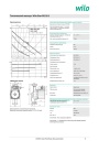
Циркуляционный насос Wilo-Star-RS 25/2. Технический паспорт. pdf, 918.98 Kb
Технический паспорт циркуляционного насоса Wilo-Star-RS 25/2: рабочие характеристики, габаритный чертёж, схема подключения, допустимые среды и область применения, материалы, данные электродвигателя.