

Инструкции на Газовые печи Lennox серии GM...
Газовые печи Lennox серии G 61 MPVT. Инструкция по монтажу.
Смотрите также: Инструкция по монтажу →
Загружаем документ…
Текст инструкции
-
INSTALLATION
INSTRUCTIONS E 2006 Lennox Industries Inc. Dallas, Texas, USA G61MPVT SERIES UNITS GAS UNITS 505,187M 01/2007 Litho U.S.A. Table of Contents Unit Dimensions . . . . . . . . . . . . . . . . . . . . . . . . . . . . . . . 2 G61MPVT Parts Arrangement . . . . . . . . . . . . . . . . . . . 3 Shipping and…
-
G61MPVT Unit Dimensions − mm
*60C and 60D size units installed in upflow applications that require air volumes over 1800 cfm (850 L/s) must have one of the following: 1. Single side return air with transition, to accommodate 20 x 25 x 1 in. (508 x 635 x 25 mm) air filter. Required to maintain proper air velocity. 2. Single side…
-
G61MPVT Parts Arrangement
TOP CAP DuralokPlusTM HEAT EXCHANGER ASSEMBLY CABINET BURNER BOX ASSEMBLY GAS VALVE AND MANIFOLD FLUE COLLAR COMBUSTION AIR PRESSURE PROVE SWITCHES WARM HEADER (COLLECTOR) BOX COMBUSTION AIR INDUCER CONDENSER COIL PRIMARY LIMIT BURNER ACCESS PANEL COLD HEADER (COLLECTOR) BOX BLOWER ACCESS PANEL…
-
G61MPVT Gas Furnace
Shipping and Packing List The G61MPVT gas furnace is equipped with a two−stage, variable speed integrated control. This control ensures compatibility with a thermostat which provides humidity control. Each G61MPVT is shipped ready for installation in the upflow, downflow, horizontal left air…
-
Upflow Applications
Installation − Setting Equipment The G61MPVT gas furnace can be installed as shipped in the upflow position. Refer to figure 3 for clearances. WARNING Installation Clearances Do not install the furnace on its front or its back. Do not connect the return air ducts to the back of the furnace. Doing so…
-
Horizontal Applications
5 − Return air from bottom and one side. Refer to Engineering Handbook for additional information. G61MPVT applications which include side return air and a condensate trap installed on the same side of the cabinet require either a return air base or field−fabricated transition to accommodate an…
-
TYPICAL HORIZONTAL ROOF SPACE INSTALLATION (FORCED AIR FURNACE)
EXHAUST PIPE INTAKE PIPE GAS CONNECTOR NOTE − Condensate trap and condensate line must be protected by self−regulating heating cable and insulation when run through unconditioned spaces. RAISED PLATFORM SERVICE PLATFORM CONDENSATE LINE FIGURE 7 Platform Installation of Horizontal Unit in Roof Space…
-
Return Air −− Horizontal Applications
Return air may be brought in only through the end of a furnace installed in the horizontal position. The furnace is equipped with a removable bottom panel to facilitate installation. See figure 5. 3 − Set the unit over the plenum and seal the plenum to the unit. 4 − Ensure that the seal is adequate.…
-
PLENUM
(Field Provided) G61MPVT UNIT ÉÉÉÉ SUPPLY AIR PLENUM PROPERLY SIZED FLOOR OPENING SECURE FROM INSIDE CABINET ADDITIVE BASE SEALING STRIP (Field Provided) CABINET SIDE PANEL Side View FIGURE 12 Filters FIGURE 10 Installation on Cooling Cabinet 1 − Refer to reverse−flow coil installation instructions…
-
with Australian standards. The solvent shall be free flowing
and contain no lumps, undissolved particles or any foreign matter that adversely affects the joint strength or chemical resistance of the cement. The cement shall show no gelation, stratification, or separation that cannot be removed by stirring. room. This reverse flow of the flue gas may result in…
-
Vent Piping Guidelines
G61MPVT furnaces, with the exception of the G61MPVT−60D−135, can be installed as either a Non−Direct Vent or a Direct Vent gas central furnace. The G61MPVT−60D−135 can only be installed as a Direct Vent (two pipe) gas central furnace. NOTE − In Non-Direct Vent installations, combustion air is taken…
-
Use the following steps to correctly size vent pipe diameter
Refer to Vent Pipe Size Determination Worksheet on page 52. 1 − Determine the vent termination and its corresponding equivalent meter value per table 6. 2 − Determine the number of 90° elbows required for both indoor and outdoor use. Calculate the corresponding equivalent meters of vent pipe. 3 −…
-
Venting Practices
1 − Use recommended piping materials for exhaust piping (Class E / Class 12 / Schedule 40). 2 − Secure all joints so that they are gas-tight using approved cement. Suspend piping using hangers at a minimum of every 1.52m (5 feet) for Schedule 40 vent pipe. A suitSTRAPPING able hanger can be…
-
TYPICAL EXHAUST PIPE CONNECTIONS AND CONDENSATE TRAP INSTALLATION
IN UPFLOW OR DOWNFLOW DIRECT OR NON−DIRECT VENT APPLICATIONS (Right−Hand Exit in Upflow Application Shown) 80mm PLUG 50mm PLUG TRANSITION 50mm 50mm VENT PLUG (Must be glued in place) 50mm G61MPVT−070 or 090 with 80mm vent pipe 50mm 50mm 80mm PLUG TRANSITION CONDENSATE TRAP (Must be installed on same…
-
TYPICAL AIR INTAKE PIPE CONNECTIONS
UPFLOW OR DOWNFLOW DIRECT VENT APPLICATIONS (Right−Hand Exit in Upflow Application Shown) 80mm TRANSITION 50mm 80mm 50mm* 50mm PLUG (Must be glued in place) TRANSITION 50mm* 50mm 50mm* 50mm G61MPVT−36B−070 G61MPVT−60C−090 G61MPVT−36B−070 G61MPVT−60C−090 G61MPVT−60C−110* G61MPVT−36B−070…
-
TYPICAL AIR INTAKE PIPE CONNECTIONS
DOWNFLOW NON−DIRECT VENT APPLICATIONS (Right−Hand Exit in Downflow Applications Shown) 50mm SWEEP ELL PLUG (Must be glued in place) INTAKE DEBRIS SCREEN (Provided) 150mm Max. PLUG (Must be glued in place) INTAKE DEBRIS SCREEN (Provided) Downflow Evaporator Coil 50mm 438mm 50mm SWEEP ELL Downflow…
-
are connected to the venting system being tested. If the
venting system has been installed improperly, or if provisions have not been made for sufficient amounts of combustion air, corrections must be made as outlined in the previous section. 1 − Seal any unused openings in the venting system. 2 − Visually inspect the venting system for proper size and…
-
VENT TERMINATION CLEARANCES
(AS 5601) − G61MPVT VENT TERMINATION − AIR INLET OF OTHER APPLIANCE C less than 10 ft (3.048M) D F D E A − Clearance above ground level − 305mm. B − Clearance horizontally to window or door that may be opened − 305mm minimum for appliances up to 150Mj/h; Clearance vertically below a window that may…
-
7 − On field supplied terminations, a minimum separation
distance between the end of the exhaust pipe and the end of the intake pipe is 203mm (8 inches). TABLE 7 EXHAUST PIPE TERMINATION SIZE REDUCTION G61MPVT MODEL Exhaust Pipe Size Termination Pipe Size or 80mm 50 or 80mm 80mm 80mm 40mm 50mm 50mm* 50mm* FIELD−PROVIDED REDUCER MAY BE REQUIRED TO ADAPT…
-
Condensate Piping
This unit is designed for either right- or left-side exit of condensate piping in either upflow or downflow applications; however, it must be installed on the same side of the unit as the exhaust piping. In horizontal applications, the condensate trap should extend below the unit. A 140mm…
-
Gas Piping
MANUAL MAIN SHUT−OFF VALVE WILL NOT HOLD NORMAL TEST PRESSURE CAUTION DO NOT over−tighten when attaching pipe or fittings to gas valve. Damage may occur. 1 − Gas piping may be routed into the unit through either the left- or right-hand side. Supply piping enters into the gas valve from the side of…
-
Horizontal Applications
Possible Gas Piping Configerations MANUAL MAIN SHUT−OFF VALVE Horizontal Application Left−Side Air Discharge MANUAL MAIN SHUT−OFF VALVE GROUND JOINT UNION GROUND JOINT UNION DRIP LEG DRIP LEG Horizontal Application Right−Side Air Discharge MANUAL MAIN SHUT−OFF VALVE GROUND JOINT UNION DRIP LEG…
-
5 − Electrically ground the unit according to local codes
NOTE − The G61MPVT furnace contains electronic components that are polarity sensitive. Make sure that the furnace is wired correctly and is properly grounded. Electrical ELECTROSTATIC DISCHARGE (ESD) Precautions and Procedures CAUTION Electrostatic discharge can affect electronic components. Take…
-
TYPICAL G61MPVT FIELD WIRING DIAGRAM
USE COPPER CONDUCTORS ONLY. FIELD INSTALLED CLASS II 24V FIELD INSTALLED LINE VOLTAGE FIGURE 31 Page 24
-
TABLE 9
Field Wiring Applications Thermostat Jumper Settings (See figure 33) W915 Heat Staging Two−Stage W914 DehuW951 Jumper midification Heat Pumps Cooling Wiring Connections 1Heat / 1 Cool NOTE − Use heat staging jumper to set second−stage heat ON delay. No delay (None), 10 minutes, or 15 minutes. 15…
-
TYPICAL G61MPVT WIRING DIAGRAM
FIGURE 32 Page 26
-
Integrated Control Board
TWO−STAGE, VARIABLE SPEED INTEGRATED CONTROL BOARD HEAT STAGING DELAY JUMPER BLOWER OFF DELAY JUMPER BLOWER OPERATION DIP SWITCHES DIAGNOSTIC LED OPERATIONAL LEDS FIGURE 33 G61MPVT units are equipped with a two−stage, variable speed integrated control. This control manages ignition timing, heating…
-
On−board jumper W914, which connects terminals DS and R on the integrated control board, must be cut when the furnace is installed with a thermostat which features humidity control. On−Board Jumper W951 On−board jumper W951, which connects terminals R and O on the integrated control board, must be…
-
OFF
100% CFM 100% CFM DEMAND 45 SEC. OFF Ramping Option D S Motor runs at 100% until demand is satisfied. S Once demand is met, motor ramps down to stop. OFF 100% CFM COOLING DEMAND OFF Switches 7 and 8 −− Heating Mode Blower Speed −− Switches 7 and 8 are used to select heating mode blower motor speed.…
-
TABLE 15
G61MPVT−60C−090 BLOWER MOTOR PERFORMANCE (LESS FILTER) 0.0" to 0.8" w.g. (0 through 200 Pa) External Static Pressure Range Factory Settings: Heating Speed − 2; Cooling Speed − 4; Speed Adjust − NORM. Return Air Options: Bottom; both sides; or bottom and one side. ADJUST" Switch Positions + NORM…
-
TABLE 17
G61MPVT−60C−090 BLOWER MOTOR PERFORMANCE (LESS FILTER) 0.0" to 0.8" w.g. (0 through 200 Pa) External Static Pressure Range Factory Settings: Heating Speed − 2; Cooling Speed − 4; Speed Adjust − NORM. Return Air Options: Single side return with optional RAB return air base ADJUST" Switch Positions +…
-
TABLE 19
G61MPVT−60C−110 BLOWER MOTOR PERFORMANCE (LESS FILTER) 0.0" to 0.8" w.g. (0 through 200 Pa) External Static Pressure Range Factory Settings: Heating Speed − 2; Cooling Speed − 4; Speed Adjust − NORM. Return Air Options: Single side return air − Bold volumes require field−fabricated transition to…
-
TABLE 21
G61MPVT−60D−135 BLOWER MOTOR PERFORMANCE (LESS FILTER) 0.0" to 0.8" w.g. (0 through 200 Pa) External Static Pressure Range Factory Settings: Heating Speed − 2; Cooling Speed − 4; Speed Adjust − NORM. Return Air Options: Bottom. ADJUST" Switch Positions + NORM ADJUST" Switch S tc P iti Positions +…
-
The gas valve on the G61MPVT is equipped with a gas
control knob. Use only your hand to turn the gas control knob. Never use tools. If the knob will not push in or turn by hand, do not try to repair it. Call a qualified service technician. Force or attempted repair may result in a fire or explosion. Placing the furnace into operation: G61MPVT units…
-
11− Set the thermostat to desired setting
3 − Remove temporary gas meter if installed. NOTE − When unit is initially started, steps 1 through 11 may need to be repeated to purge air from gas line. NOTE − To obtain accurate reading, shut off all other gas appliances connected to meter. 12− If the appliance will not operate, follow the…
-
TABLE 23
Conversion Kit Requirements for Models −070, −090, −110 and −135 Model Input Size High Altitude Pressure Switch Kit ORDER TWO EACH Natural Gas to LPG / Propane Kit 611 − 1372 m LPG / Propane Gas to Natural Gas Kit 0 − 610 m 611 − 1372 m 59M17 56M23 N/A No change N/A No Change 59M14 56M23 59M13 No…
-
Electronic Ignition
The integrated control has an added feature of an internal Watchguard control. The feature serves as an automatic reset device for ignition control lockout caused by ignition failure. This type of lockout is usually due to low gas line pressure. After one hour of continuous thermostat demand for…
-
5 − If the heating demand continues beyond the second−
stage on delay, the integrated control energizes the combustion air inducer at high speed. The control also checks the high−fire (second stage) pressure switch to make sure it is closed. Once the control receives a signal the high−fire pressure switch is closed, the high−fire (second stage) gas…
-
16 − Mark and disconnect any remaining wiring to heating
compartment components. Disengage strain relief bushing and pull wiring and bushing through the hole in the blower deck. 17 − Remove the primary limit from the vestibule panel. 18 − Remove two screws from the front cabinet flange at the blower deck. Spread cabinet sides slightly to allow clearance…
-
Requirements
Use only the type of gas approved for use with this furnace. Refer to unit nameplate. G61MPVT units are certified for installation clearances to combustible material as listed on the unit nameplate and in the tables in figures 3, 9 and 6. Accessibility and service clearances must take precedence…
-
• When the furnace is installed in an attic or other insulated space, keep insulation away from the furnace. • When the furnace is installed in an unconditioned space, consider provisions required to prevent freezing of condensate drain system. CAUTION G61MPVT unit should not be installed in areas…
-
Unconfined Space
An unconfined space is an area such as a basement or large equipment room with a volume greater than 1.42 m3 per .29 kW (50 cubic feet per 1,000Btu) per hour of the combined input rating of all appliances installed in that space. This space also includes adjacent rooms which are not separated by a…
-
When ducts are used, they shall be of the same cross−sectional area as the free area of the openings to which they connect. The minimum dimension of rectangular air ducts shall be no less than 75mm (3 inches). In calculating free area, the blocking effect of louvers, grilles, or screens must be…
-
Ignition Control Board Diagnostic Codes (Red LED)
FLASH CODE (X + Y) STATUS / ERROR DESCRIPTION FLASH CODE DESCRIPTIONS Pulse A 1/4 second flash followed by four seconds of off time. Heartbeat Constant 1/2 second bright and 1/2 second dim cycles. X+Y LED flashes X times at 2Hz, remains off for two seconds, flashes Y times at 2Hz, remains off for…
-
Troubleshooting: Heating Sequence of Operation
HEATING SEQUENCE OF OPERATION NORMAL AND ABNORMAL HEATING MODE POWER ON CONTROL SELF−CHECK OKAY? POLARITY OKAY? GAS VALVE OFF. COMBUSTION AIR INDUCER OFF. INDOOR BLOWER OFF. (RESET CONTROL BY TURNING MAIN POWER OFF.) NO POLARITY REVERSED. STATUS ERROR CODE 5 + 4. NO YES IS THERE A PROPER GROUND? NO…
-
CONTINUED
THERMOSTAT CALLS FOR HEAT STATUS LED − HEARTBEAT (Refer to box A on previous page) NO FIRST−STAGE (LOW FIRE) PRESSURE SWITCH CLOSED WITHIN 2.5 MINUTES? YES GAS VALVE OFF. COMBUSTION AIR INDUCER OFF. INDOOR BLOWER OFF. UNIT WILL RETRY AFTER 5−MINUTE WAIT PERIOD. STATUS ERROR CODE 2 + 3. 15−SECOND…
-
CONTINUED
THERMOSTAT CALLS FOR HEAT. STATUS LED −− HEARTBEAT. SEE BOX A. FLAME SIGNAL ABOVE (u1.40 microamps) NO LOW FLAME SIGNAL (Does not affect control operation) STATUS ERROR CODE 1 + 2. YES YES SINGLE−STAGE THERMOSTAT MODE (Heat staging jumper on 10 or 15 minutes) TWO STAGE THERMOSTAT MODE (Heat staging…
-
CONTINUED
SEE BOX A NORMAL OPERATION. SEE BOX B THERMOSTAT CALLS FOR HEAT. SECOND−STAGE (HIGH FIRE) HEAT PRESSURE SWITCH CLOSED? RETURN TO FIRST−STAGE HEAT MODE. FIRST−STAGE CONTINUES UNTIL SECOND− STAGE PRESSURE SWITCH CAN BE PROVEN or HEAT DEMAND IS SATISFIED. A FIVE (5) MINUTE WAIT PERIOD IS INITIATED…
-
Troubleshooting: Cooling Sequence of Operation
COOLING SEQUENCE OF OPERATION POWER ON YES IS POLARITY REVERSED? SIGNAL POLARITY REVERSED. CONTROL WILL CONTINUE TO CALL FOR COOLING IN THIS CONDITION. STATUS ERROR CODE 5 + 4. NO IS THERE PROPER GROUND? SIGNAL IMPROPER GROUND AT LED. CONTROL WILL CONTINUE TO CALL FOR COOLING IN THIS CONDITION.…
-
Troubleshooting: Continuous Fan Sequence of Operation
CONTINUOUS LOW SPEED FAN SEQUENCE OF OPERATION MANUAL FAN SELECTION MADE AT THERMOSTAT. AFTER 2 SECOND DELAY, INDOOR BLOWER IS ENERGIZED ON CONTINUOUS FAN SPEED. YES YES THERMOSTAT CALLS FOR FIRST STAGE COOL. THERMOSTAT CALLS FOR FIRST−STAGE HEAT. YES YES YES INDOOR BLOWER RAMPS TO FIRST STAGE…
-
Repair Parts List
The following repair parts are available through Lennox dealers. When ordering parts, include the complete furnace model number listed on the nameplate −− Example: G61MPVT−36B−070−01. Heating Parts Cabinet Parts Upper access panel Blower access panel Top Cap Control Panel Parts Transformer…
-
G61MPVT Start−Up & Performance Check List
Job Name Job No. Date Job Location City State Installer Unit Model No. Serial No. City Technician State Heating Section Electrical Connections Tight? Supply Voltage Blower Motor H.P. Blower Motor Amps Gas Piping Connections Tight & Leak−Tested? LP/Propane Gas? Fuel Type: Natural Gas? Furnace Btu…
Схемы, таблицы и рисунки — в просмотре документа выше. Клик по номеру страницы открывает её в просмотре.
Новое в каталогах
-
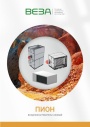
Каталог продукции Веза 2026 - Воздухонагреватели газовые ПИОН. pdf, 6.55 Mb
Каталог газовых воздухонагревателей ПИОН: назначение, конструкция и исполнения, технические характеристики, габаритные размеры, обозначение при заказе. -
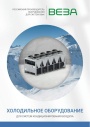
Каталог продукции Веза 2026 - Холодильное оборудование для систем кондиционирования воздуха. pdf, 4.97 Mb
Каталог холодильного оборудования Веза для систем кондиционирования: чиллеры, компрессорно-конденсаторные блоки, фанкойлы и другое оборудование — технические характеристики, габаритные размеры, обозначение при заказе. -
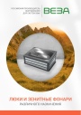
Каталог продукции Веза 2025 - Люки и зенитные фонари различного назначения. pdf, 8.45 Mb
Каталог люков дымоудаления и зенитных фонарей Веза различного назначения: конструкция и исполнения, приводы и автоматика, технические характеристики, габаритные размеры.
Новое в инструкциях
-
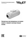
Компактные приточные установки Shuft серии AirTube. pdf, 350.53 Kb
Модели: AirTube 160, 200, 250, 315. Паспорт (объединённый эксплуатационный документ): описание устройства, монтаж, подключение электропитания, схемы электрических соединений, обслуживание, поиск и устранение неисправностей, гарантия, технические данные. -
Приточные установки Shuft серии Eco-Slim. pdf, 8.64 Mb
Модели: Eco-Slim 350, 700, 1100, 1100 W. Паспорт (объединённый эксплуатационный документ) установок с электрическим и водяным нагревателем: технические характеристики, монтаж, схема электрического подключения, обслуживание, пульт управления «Oazis», неисправности. -
Канальные фанкойлы Shuft серии SFF. pdf, 1.91 Mb
Модели: SFF-200G50 … SFF-1400G50. Инструкция по эксплуатации средненапорных канальных фанкойлов: внешние виды и размеры, технические характеристики, монтаж, электропроводка, техническое обслуживание, устранение неисправностей.