

Инструкция на Компрессорно-конденсаторные блоки Lennox серии HS...
Компрессорно-конденсаторные блоки Lennox серии HS 14. Инструкция по сервисному обслуживанию.
Смотрите также: Основной документ →
Загружаем документ…
Текст инструкции
-
LENNOX ие, tes inc. Corp. 815-15 Litho U.S.A. о р HS14 SERIES UNITS WITH “L7” TWO SPEED COMPRESSOR |- INTRODUCTION The HS14 features the Lennox two speed compressor which shifts speeds to match load requirements. At low speed it cuts energy consumption by nearly 50% over a single speed compressor.…
-
С - Pressure Curves
-
D - Dimensions
| Model No. | A B с о HS14-411V 34-1/2 | 4-1/2 | 11-114 | 1-1/2 HS14-413V HS14-511V 34-1/2 | 5-7/8 12 | 2-116 HS14-513V HS14-651V 39-1/2 | 5-7/8 12 | 2-116 HS14-653V 32-18 Г :.1.7.9 = | ох LIQUID LINE VALVE AND GAUGE PORT А suction LINE CONNECTION SUCTION LINE vaLve~_ [|5 ~ AND GAUGE PORT {Inside…
-
Е - Typical Field Wiring Diagram (Figure 2)
High voltage pigtail leads are provided in the make-up area of control box for connection to power supply. A ground lug is also provided. Note on unit wire sizing & fuse selection - Minimum circuit ampacity and maximum fuse size are listed on the unit nameplate {also on pg. 1 under ‘Electrical Data’…
-
ROOM THERMOSTAT Г) DEHUMIDISTAT INDOOR UNIT
| NOTE — CONTACT CLOSES ON INCREASE IN | HUMIDITY соя xO (3) + 1 I г--3 LATENT LOAD KIT CONTROL BOX RED ee Lf" oo rity в Е Spe 2 1} lo HS14 UNIT tq | at 3! lve. в 1 io fm tai [ TERMINAL orl Е CONTROL вох rr | \ ! Se | р Е py byte rot | Г | > | | irl > |i | a = | < + #15 | it ы | x| 518 11 Е | Е ; a…
-
IV - COMPONENTS
А - Control Box (Figure 4) 1 - Protection Module The module connects to sensors within the compressor motor windings through S1 and S2. The module is supplied with 24 VAC at terminals P1 & P2. The cornpressor control circuit is connected to K1 & K2. If the sensors detect excessive winding…
-
3 - Potential Relay (КЗ) (Single phase units only)
Used to disconnect the start capacitor from the circuit when the compressor reaches operating speed. The potential relays are matched specifically to each compressor size. See table for operating voltage. Cold Coil Operating Voltages (VAC HS14 | Min. | Max. Min. Max. Unit_] Pickup | Pickup | Dropout…
-
С - Room Thermostat (Figure 6)
HS14 units use a two stage cooling - single stage heating AUN WINDING thermostat. Mode of operation indicator lights give visual! TERMINAL 1, 2&7 readout of “Low” and “High” speed compressor operation. N\, The green light comes on during low speed and the amber light comes on during high speed.…
-
low speed start windings are in series and connected to
terminals 1 (common) & 8. They are used with the start & run capacitors and potential relay to start and bring the motor up to speed. High speed compressor motor operation is provided when the run windings are connected in parallel; terminals 1 (common) & 7 to L1 and terminal 2 to L2. The windings…
-
М! - COMPRESSOR PROTECTION MODULE
CHECKOUT Thermal sensors embedded within the compressor windings change resistance in direct relationship to temperature change. The trip setting ranges from 16K to 24K while reset Provide a cooling demand and check K1 and K2. Power indicates another component is open. Check power to module, Remove…
-
Н$14
У! - SCHEMATIC WIRING DIAGRAM OPER- accessory SEQUENCE ATING SEQUENCE A - Latent Load Discriminator Kit (Figure 23) Each of the following steps within this section are labeled in the corresponding diagram. SINGLE PHASE LOW SPEED A - 24 Volt Control Circuit (Figure 13) 1 - Thermostat demand on first…
-
В - Compressor Starting Circuit (Figure 14} completes the circuit to L1 thru K4 low speed contactor
1 - To energize the start windings with the proper torque the L6-T6 contacts. start and run capacitors are in parallel for maximum capacitance value. L2 Thru: K3- Fan Relay М.О. Contacts C2 - Start Capacitor C3 - Run Capacitor(s) RT - Current Limiting Device K6 - Potential Relay N.C. Contacts K4…
-
С - Compressor Run Circuit (Figure 15) 3 - The run capacitor(s) rernain connected to the start wind-
1- At the same time the start windings are energized the ings thru K3 fan relay and K4 contacts L8-T8. The run compressor run windings (in series) are powered thru К4 capacitors create the proper amount of voltage phase ом speed contactor (contacts L6-T6 & L7-T7). shift to improve the power factor…
-
О - Current Limiting Device Function (Figure 16)
The current limiting device (RT) is a NTC thermistor (increase in temperature equals decrease in resistance). It is used in the compressor starting circuit in series between the potential relay contacts and the start capacitor. 1 - Аз the compressor is started RT heats fast lowering its resistance…
-
SINGLE PHASE HIGH SPEED
А - 24 Volt Control Circuit (Figure 17) i - Thermostat demand on second stage (Y2) energizes K2 control relay No. 2. 2- Thru: Protection Module N.C. Circuit - P2 to K1 $1 - High Pressure Switch S2 - Low Pressure Switch K2-1 - Control Rly No. 2 N.O. Contacts K4-2 - Low Spd Contactor N.C. Contacts…
-
В - Compressor Starting Circuit (Figure 18)
-
С - Compressor Run Circuit (Figure 19)
At the same time the start windings are energized the com- 4 - The run capacitor(s) remain connected to the start windлеззог run windings (т parallel) are powered thru КБ high ings thru K3 fan relay and K5 contacts L3-T3. speed contactor as follows: 1-L1 Power thru КБ contacts L1-T1 & L4-T4 to…
-
THREE PHASE OPERATION А - Compressor Circuit - Low Speed (Figure 20)
The 3¢ low voltage circuits operate the same as the 19 low 1 - K4-1 jow speed compressor contactor and K3-2 fan relay voltage circuits. (Refer to figures 13 & 17) are energized by low voltage circuit. 2 - Fanis energized, crankcase heater is de-energized by K3-2 fan relay contacts. 3 - Compressor…
-
В - Compressor Circuit - High Speed (Figure 21)
* - K5-1 high speed compressor contactor and K3-2 fan relay are energized by low voltage circuit. 2 - Fan is energized, crankcase heater is de-energized by K3-2 fan relay contacts. HS14 3 - Compressor terminals 4, 5, & 6 are energized thru K5-1 contacts L1-T1, L2-T2 & L3-T3. And compressor winding…
-
ACCESSORY SEQUENCE humidity rises sufficiently
A - Latent Load Discriminator Kit (Optional) (Figure 23) The latent load kit functions during low speed compressor operation to lower the indoor blower motor speed for in- The latent load relay N.C. contacts open de-energizing high blower speed & the N.O. contacts close energizing ee low speed.…
Схемы, таблицы и рисунки — в просмотре документа выше. Клик по номеру страницы открывает её в просмотре.
Новое в каталогах
-

Каталог продукции Веза 2026 - Оборудование для противодымной вентиляции. pdf, 7.85 Mb
Каталог оборудования Веза для противодымной вентиляции: вентиляторы дымоудаления и подпора, противопожарные клапаны, люки и прочее оборудование — назначение, технические характеристики, габаритные размеры. -
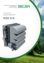
Каталог продукции Веза - Воздухоприемное устройство РОН 510. pdf, 1.96 Mb
Каталог воздухоприёмных устройств РОН 510: назначение, конструкция, технические характеристики, габаритные размеры, обозначение при заказе. -
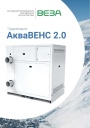
Каталог продукции Веза 2026 - Гидромодули АкваВЕНС 2.0. pdf, 1.29 Mb
Каталог гидромодулей АкваВЕНС 2.0: назначение, конструкция и исполнения, гидравлические схемы, технические характеристики, габаритные размеры, обозначение при заказе.
Новое в инструкциях
-
Крышные вентиляторы Shuft серии RMV VIM. pdf, 4.41 Mb
Модели: RMVE 190/300-2 … 450/670-4, RMVD 311/440-4 … 630/950-4 VIM. Паспорт (объединённый эксплуатационный документ): описание, массогабаритные показатели, монтаж, схемы электрических соединений, пуск, обслуживание, гарантийные обязательства, технические данные. -
Вентиляторы в круглом корпусе Shuft серии SH. pdf, 646.47 Kb
Модели: SH 160, 200, 250, 315, 400. Руководство по установке, эксплуатации и техническому обслуживанию: технические характеристики, размеры, монтаж, электрические подключения, ввод в эксплуатацию, обслуживание и чистка, устранение неисправностей. -
Приточно-вытяжные установки Shuft серии NOVA. pdf, 4.29 Mb
Модель NOVA-300. Инструкция по монтажу и обслуживанию: принципиальная схема установки, массогабаритные показатели, монтаж воздуховодов и дренажа, подключение электропитания, схема электрических соединений, пусконаладка, обслуживание, неисправности, подключение к системе диспетчеризации.