

Инструкция на Rooftops (крышные кондиционеры) Lennox серии SMART LINEА
Rooftops (крышные кондиционеры) Lennox серии LGA / LCA248H, LGC / LCC300H, LGA / LCA360H. Руководство по эксплуатации.
Смотрите также: Руководство по эксплуатации →
Загружаем документ…
Текст инструкции
-
INSTALLATION
INSTRUCTIONS Litho U.S.A. 2003 RETAIN THESE INSTRUCTIONS FOR FUTURE REFERENCE WARNING Improper installation, adjustment, alteration, service or maintenance can cause property damage, personal injury or loss of life. Installation and service must be performed by a qualified installer, service agency…
-
LGA/LCA/LGC/LCC248, 300 & 360 Dimensions − LGA Heat Section Shown
Note: Optional equipment shown for information only. See Engineering Handbook for standard and optional features. EE 4-1/4 (108) BB OPTIONAL ECONOMIZER DAMPERS (Factory or Field Installed) 78-1/2 (1994) BOTTOM RETURN AIR OPENING CENTER OF GRAVITY 18 (457) EVAPORATOR COIL 28 28 (711) (711) 4-1/2 20…
-
Shipping and Packing List
SERVICE CLEARANCES ÇÇÇÇÇÇÇ ÇÇÇÇÇÇÇ ÇÇÇÇÇ ÇÇÇ ÇÇÇÇÇÇÇ ÇÇÇÇÇ ÇÇÇ ÇÇÇÇÇ ÇÇÇ ÇÇÇÇÇ ÇÇÇ ÇÇÇÇÇÇÇ ÇÇÇÇÇ ÇÇÇ ÇÇÇÇÇÇÇ ÇÇÇÇÇÇÇ TOP CLEARANCE UNOBSTRUCTED Package 1 of 1 contains: 1− Assembled unit 36 (914) Check unit for shipping damage. Receiving party should contact last carrier immediately if shipping…
-
Unit Support − Continued
CAUTION Installer’s Roof Mounting Frame Many types of roof frames can be used to install the unit depending upon different roof structures. Items to keep in mind when using the building frame or supports are: 1− The base is fully enclosed and insulated, so an enclosed frame is not required. 2− The…
-
Condensate Drains
OUTSIDE OF UNIT GAS PIPE CONNECTION Make drain connection to the 1" N.P.T. drain coupling provided on unit. A trap must be installed between drain connection and an open vent for proper condensate removal. See figure 3. It is sometimes acceptable to drain condensate onto the roof or grade; however…
-
Pressure Test Gas Piping (Gas Units)
When pressure testing gas lines, the gas valve must be disconnected and isolated. Gas valves can be damaged if subjected to more than 0.5 psig (3.5kPa). See figure 7. NOTE−Codes may require that manual main shut−off valve and union (furnished by installer) be installed in gas line external to unit.…
-
INTAKE HOOD
CAULK EACH END (FIELD INSTALLED) UNIT TOP SEAL HOOD STIFFENER HOOD TOP HOOD TOP HOOD SIDE SIDE FILTER BRACKETS LONGER TOP FILTER BRACKET FIGURE 8 HOOD SIDE VIEW HOOD TOP SEAL HOOD STIFFENER HOOD TOP FILTER TOP FILTER BRACKET ALIGN VERTICAL HOLES ON BRACKET WITH VERTICAL HOLES ON SIDE OF HOOD BOTTOM…
-
B−Control Wiring
Electrical Connections POWER SUPPLY Do not apply power or close disconnect switch until installation is complete. Refer to start−up directions. Refer closely to unit wiring diagram. Refer to unit nameplate for minimum circuit ampacity and maximum fuse size. 1− 230/460/575 volt units are factory…
-
C−Determining Unit CFM
Blower Operation and Adjustments 1− The following measurements must be made with a dry indoor coil. Run blower without a cooling demand. Measure the indoor blower shaft RPM. Air filters must be in place when measurements are taken. IMPORTANT Three phase scroll compressors must be phased sequentially…
-
TABLE 3
FACTORY INSTALLED OPTIONS/FIELD INSTALLED ACCESSORY AIR RESISTANCE BLOWER TABLE INCLUDES RESISTANCE FOR BASE UNIT ONLY WITH DRY INDOOR COIL & AIR FILTERS IN PLACE. FOR ALL UNITS ADD: 1 − Wet indoor coil air resistance of selected unit. 2 − Any factory installed options air resistance (heat section…
-
TABLE 4
FACTORY INSTALLED OPTIONS/FIELD INSTALLED ACCESSORY AIR RESISTANCE Total Resistance inches water gauge (Pa) Air Volume Low Fire High Fire Electric H t Heat (LCA/LCC Models) .04 (10) .12 (30) .19 (47) .02 (5) .01 (3) .08 (20) .01 (2) 3070 .05 (13) .13 (32) .21 (52) .02 (5) .01 (3) .09 (22) .01 (2)…
-
2− Apply perpendicular force to center of span (X) with
enough pressure to deflect belt 1/64" for every inch of span length or 1.5mm per 100mm of span length. Example: Deflection distance of a 40" span would be 40/64" or 5/8". Cooling Start−Up IMPORTANT−The crankcase heater must be energized for 24 hours before attempting to start compressor. Set…
-
A−Preliminary Checks
1− Make sure that unit is installed in accordance with the installation instructions and applicable codes. 2− Inspect all electrical wiring, both field- and factory-installed, for loose connections. Tighten as required. 3− Check to ensure that refrigerant lines do not rub against the cabinet or…
-
360H REFRIGERANT CIRCUITS
(30 TON) STAGE 1 CONDENSER COILS EVAPORATOR COIL STAGE 2 EVAPORATOR COIL STAGE 1 EVAPORATOR COIL STAGE 2 CONDENSER COILS FIGURE 15 NOTE − System charging is not recommended below Cooling Start−Up − Continued 60_F (15_C). In temperatures below 60_F (15_C) , the D−R410A Refrigerant charge must be…
-
6− If discharge pressure is high, remove refrigerant from
the system. If discharge pressure is low, add refrigerant to the system. TABLE 11 LGA/LCA360H − R22 D Add or remove charge in increments. D Allow the system to stabilize each time refrigerant is added or removed. 7− Use the following approach method along with the normal operating pressures to…
-
G−Compressor Controls
See unit wiring diagram to determine which controls are used on each unit. 1− High Pressure Switch (S4, S7, S28, S96) R22 The compressor circuit is protected by a high pressure switch which cuts out at 450 psig + 10 psig (3103 kPa + 70 kPa) and automatically resets at 300 psig + 20psig (2069kPa +…
-
Gas Heat Start−Up (Gas Units)
FOR YOUR SAFETY READ BEFORE LIGHTING BEFORE LIGHTING smell all around the appliance area for gas. Be sure to smell next to the floor because some gas is heavier than air and will settle on the floor. This unit is equipped with an automatic spark ignition system. There is no pilot. In case of a…
-
6− Wait five minutes to clear out any gas. If you then
smell gas, STOP! Immediately call your gas supplier from a neighbor’s phone. Follow the gas supplier’s instructions. If you do not smell gas, go to the next step. 7− Turn the knob on the gas valve counterclockwise to ON. Do not force. 6− For troubleshooting purposes, an ignition attempt after lock…
-
3− Remove the right burner and check the alignment of
the ignition sensor. See figure 21. 4− Replace burners and burner support cap. Secure cap in place with retained screws. 5− The following manifold pressures are listed on gas valves. Natural Gas Units − Low Fire − 1.6" w.c. (not adjustable) Natural Gas Units − High Fire − 3.7" w.c. LP Gas Units −…
-
C−Burners (Gas Units)
HEAT EXCHANGER ASSEMBLY 1− Periodically examine burner flames for proper appearance during the heating season. 2− Before each heating season examine the burners for any deposits or blockage which may have occurred. 3− Clean burners as follows: a− Turn off both electrical power and gas supply to…
Схемы, таблицы и рисунки — в просмотре документа выше. Клик по номеру страницы открывает её в просмотре.
Новое в каталогах
-
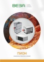
Каталог продукции Веза 2026 - Воздухонагреватели газовые ПИОН. pdf, 6.55 Mb
Каталог газовых воздухонагревателей ПИОН: назначение, конструкция и исполнения, технические характеристики, габаритные размеры, обозначение при заказе. -
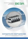
Каталог продукции Веза 2026 - Холодильное оборудование для систем кондиционирования воздуха. pdf, 4.97 Mb
Каталог холодильного оборудования Веза для систем кондиционирования: чиллеры, компрессорно-конденсаторные блоки, фанкойлы и другое оборудование — технические характеристики, габаритные размеры, обозначение при заказе. -
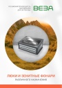
Каталог продукции Веза 2025 - Люки и зенитные фонари различного назначения. pdf, 8.45 Mb
Каталог люков дымоудаления и зенитных фонарей Веза различного назначения: конструкция и исполнения, приводы и автоматика, технические характеристики, габаритные размеры.
Новое в инструкциях
-
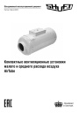
Компактные приточные установки Shuft серии AirTube. pdf, 350.53 Kb
Модели: AirTube 160, 200, 250, 315. Паспорт (объединённый эксплуатационный документ): описание устройства, монтаж, подключение электропитания, схемы электрических соединений, обслуживание, поиск и устранение неисправностей, гарантия, технические данные. -
Приточные установки Shuft серии Eco-Slim. pdf, 8.64 Mb
Модели: Eco-Slim 350, 700, 1100, 1100 W. Паспорт (объединённый эксплуатационный документ) установок с электрическим и водяным нагревателем: технические характеристики, монтаж, схема электрического подключения, обслуживание, пульт управления «Oazis», неисправности. -
Канальные фанкойлы Shuft серии SFF. pdf, 1.91 Mb
Модели: SFF-200G50 … SFF-1400G50. Инструкция по эксплуатации средненапорных канальных фанкойлов: внешние виды и размеры, технические характеристики, монтаж, электропроводка, техническое обслуживание, устранение неисправностей.