

Инструкция на Rooftops (крышные кондиционеры) Lennox серии BALTIC
Rooftops (крышные кондиционеры) Lennox серии BALTIC_WSHP-IOM-0909-E: BAC020SNM, BAH020SNM, BAG020SHM, BAG045SSM, BAM020SHM, BAM045SSM, BAC030SNM, BAH030SNM, BAG020SSM, BAG055SHM, BAM020SSM, BAM055SHM, BAC035SNM, BAH035SNM, BAG030SHM, BAG055SSM, BAM030SHM, BAM055SSM, BAC045SNM, BAH045SNM, BAG030SSM, BAG065DHM, BAM030SSM, BAM065DHM, BAC055SNM, BAH055SNM, BAG035SHM, BAG065DSM, BAM035SHM, BAM065DSM, BAC065DNM, BAH065DNM, BAG035SSM, BAG075DHM, BAM035SSM, BAM075DHM, BAC075DNM, BAH075DNM, BAG045SHM, BAG075DSM, BAM045SHM, BAM075DSM, BWH045SNM, BWH055SNM, BWH065DNM, BWH075DNM, BWM045SHM, BWM045SSM, BWM055SHM, BWM055SSM, BWM065DHM, BWM065DSM, BWM075DHM, BWM075DSM. Инструкция по монтажу, эксплуатации и техническому обслуживанию.
Смотрите также: Основной документ →
Загружаем документ…
Текст инструкции
-
Installation, operating
and maintenance BALTIC & BALTIC WSHP Providing indoor climate comfort BALTIC-WSHP-IOM-0909-E
-
INSTALLATION
OPERATION MAINTENANCE MANUAL Ref. BALTIC_WSHP-IOM-0909-E The present manual applies to the following ROOFTOP versions: BAC020SNM BAH020SNM BAG020SHM BAG045SSM BAM020SHM BAM045SSM BAC030SNM BAH030SNM BAG020SSM BAG055SHM BAM020SSM BAM055SHM BAC035SNM BAH035SNM BAG030SHM BAG055SSM BAM030SHM BAM055SSM…
-
PRESSURE EQUIPMENT
All Baltic Units are compliant with the PED directive 97-23/CE The following note must be followed carefully All work on the unit must be carried out by a qualified and authorised employee. Non-compliance with the following instructions may result in injury or serious accidents. Work on the unit: •…
-
Refer to control section page 55 / Se référer à la section régulation page 55
Time Zones / Zones Horaires Hour UNO Example 7h15 ZA 11h00 ZB 14h00 19h00 ZC UNO Monday Tuesday Wednesday Thursday Friday Saturday Sunday Variables to adjust for each time zone / Consignes à renseigner pour chaque zone horaire Start z.A Start z.B Start z.C Start UNO hour (3211) min (3212) hour…
-
REFRIGERANT TRANSACTIONS LOGBOOK: EC Regulation No 842/2006
GENERAL INFORMATION Site Name Site Address Site Operator Cooling Load Refrigerant Type Unit Manufacturer Serial Number Refrigerant Quantity (kg) Year of Installation REFRIGERANT ADDITIONS Date Engineer Quantity (kg) Reason for Addition REFRIGERANT REMOVAL Date Engineer Quantity (kg) Reason for…
-
LEAK TESTS (Part 2)
Date Engineer Test Result Follow Up Action Required FOLLOW UP ACTIONS Date Engineer Related to test dated Action Taken TESTING of AUTOMATIC LEAK DETECTION SYSTEM (If fitted) Date Engineer Test Result Comments Remarks: BALTIC_WSHP-IOM-0909-E Page 9
-
COMMENTS
BALTIC_WSHP-IOM-0909-E Page 10
-
DELIVERY CHECKS
STORAGE On receipt of a new equipment please check the following points. It is the customer’s responsibility to ensure that the products are in good working order: When units are delivered on site they are not always required immediately and are sometimes put into storage. In the event of medium to…
-
TRANSPORT – HANDLING - WARNING
MANDATORY HANDLING DEVICES Handling slings to guide the unit towards the roofcurb Vacuum lifting beam to position the unit COMPLIANT BALTIC_WSHP-IOM-0909-E NON-COMPLIANT Page 12
-
DIMENSIONS AND WEIGHTS
Fig. 4 BALTIC BAC/BAH/BAG/BAM A mm 2017 2017 1890 1910 1910 2260 2260 B mm 1418 1418 1915 2235 2235 2873 2873 C mm 1220 1220 1221 1221 1221 1225 1225 D mm Without hood kg With hood kg Standard heat without hood kg Standard heat with hood kg 1001 High heat without hood kg 1019 High heat with hood kg…
-
ONLY FOR WATER CONDENSING
BALTIC WATER COOLED BWH/BWM Figure A B C D Weight of standard units FWH Without hood With hood Weight gas unit FWM Standard heat without hood Standard heat with hood High heat without hood High heat with hood mm mm mm mm 3 1910 2235 1221 418 3 1910 2235 1221 418 4 2260 2873 1225 418 4 2260 2873 1225…
-
LIFTING THE UNITS
B BOX 1850 (mini) 1410 (mini) C BOX 1930 (mini) Fig. 5 2250 (mini) 1700 (mini) Fig. 6 2890 (mini) 2080 (mini) 1700 (mini) Fig. 7 Fig. 8 RETRACTABLE LIFTING LUG Fig. 9 BALTIC_WSHP-IOM-0909-E Page 15
-
LIFTING THE ROOF CURBS
-
MULTIDIRECTIONNAL ROOF CURB
-
PRELIMINARY CHECKS
FORKLIFT PROTECTIONS REMOVE THE FORKLIFT PROTECTIONS BEFORE INSTALLATION Fig. 15 PRELIMINARY CHECKS INSTALLATION REQUIREMENTS Before installing the equipment, the following points MUST be checked: - Have the forklift protections been removed? - Is there sufficient space for the equipment? - Is the…
-
CLEARANCES AROUND THE UNIT
MINIMUM CLEARANCE AROUND THE UNIT Figure 4 shows the required clearances and service access around the unit. NOTE: Ensure the fresh air inlet does not face prevailing wind direction. Fig. 16 B Box C Box D Box E Box A 1000 (1) 1200 (1) 1400 (1) 1800 (1) B 1500 (2) 1500 (2) 1500 (2) 1500 (2) C 1500…
-
DUCT CONNECTIONS
RECOMMENDATIONS FOR DUCTS CONNECTIONS Some rules must be complied with for the connections between ducts and unit done on site. Whatever the supply configuration is, respect a minimal duct’s length (D) of 2m before any elbow or any duct’s diameter change. These recommendations are imperative in the…
-
WATER CONNECTIONS
WATER CONNECTIONS (ONLY FOR WATER CONDENSING) Water connections The water circulating pump will be preferably installed upstream so that the evaporator/condenser will be subjected to positive pressure. Inlet and Outlet water connections are indicated on the certified drawing sent with the unit or…
-
WATER CONNECTIONS
Antifreeze protection Use glycol/water solution ADDITION OF GLYCOL IS THE ONLY EFFICIENT WAY TO PROTECT AGAINST FREEZING The glycol/water solution must be sufficiently concentrated to ensure proper protection and prevent formation of ice at the lowest outdoor air temperatures expected on an…
-
WATER CONDENSING
WATER LOOP CONFIGURATION (FOR WATER SOURCE HEAT PUMP) Figures below show the 2 water configurations. Figure 1 indicates all components used as standard : • the electronic water flow switch, • the water filter, • the pressure taps and drain valves, • the automatic airvent, The second figure shows…
-
таблицы и схемы — в просмотре
-
POSITIONING ROOFCURBS
As levels are adjustable, observe the following recommendations when installing the equipment. Above all, ensure that all the adjustable returns are facing outward (“1” figure 17). They are usually turned inside-out for transport. Fig. 17 Place the roof mounting frame on the trimmer beam by first…
-
NON ADJUSTABLE NON ASSEMBLED ROOFCURB INSTALLATION
FRAME PARTS IDENTIFICATION Figure 20 shows the different parts used in the assembly of this roof mounting frame. INSTALLATION The roof mounting frame provides support when the units are installed in down-flow configurations. The non adjustable, non assembled roof mounting frame can be installed…
-
NON ADJUSTABLE NON ASSEMBLED ROOFCURB
ASSEMBLY The frame is supplied as a single package and shipped folded down for ease of transport and handling. It is easy field assembled as all parts required are supplied with the frame. SECURING THE FRAME To ensure proper mating with units (figure 22), it is mandatory that the roof mounting frame…
-
SECURING THE CURB
When the frame is correctly positioned, it is essential to secure the assembly with a disconnected stitched welded seam (20 to 30mm every 200mm ) along the outside or by using an alternative method. Fig. 23 CURBING AND FLASHING Outside of frame must be insulated with rigid type insulation; We…
-
Heat Recovery Installation
Fig. 25 1) The unit being already erected on the roof curb, position the elbow by plugging the returns (A) in the slits (B) of the framework of the unit: see detail 1 2) Fix the elbow with caged nuts at envisaged places (C) 3) Apply mastic on the two side studs and on the superior stud of the energy…
-
INSTALLATION PROCEDURE
Screw A Lifting lugs After unfixing the screw ref A, move the 4 lifting lugs out of the frame then fix it again Remove the 2 screws for each forklift protection Remove the forklift protection before putting the machine on the roofcurb BALTIC_WSHP-IOM-0909-E Use protection between the machine and the…
-
The baltic is moving down to the curb, the
forklift protection are removed Underneath view Put smoothly the heaviest side and then adjust (Compressor side). Curb Lifting lugs B Take off the roofcurb lifting lug screws, as well as screws (B) that will be used to fix the heat recovery module. BALTIC_WSHP-IOM-0909-E Take off the top angle from…
-
Cut the hood top angle sealant and take off the
angle. Take off the hood top sheetmetal. Take off the 2 hood triangle sides and the 3 last screws that will be used to fix the heat recovery support Bring the support (by crane or by hand) close to the Rooftop. The top bend must fit into the frame rectangle slots BALTIC_WSHP-IOM-0909-E Page 32
-
The sheet metal return must inside the frame slot
Joint noir 20 x 10 Assembly the module support on the roofcurb side: 3 screws 6 x 20 inox on both sides Bring the module on the support. Check the good shape of the 20 x 10 black gaskets. BALTIC_WSHP-IOM-0909-E Page 33
-
End view
Use the self drilling screw 5 x 16 to assembly the module flanges directly in the Rooftop Corners Idem on the right side Putty the polyurethane sealant inside the junction between rooftop and heat recovery module. BALTIC_WSHP-IOM-0909-E Page 34
-
Putty very carefully on the roof side and then and flanges sides
The following components should be delivered inside the module. Connect the 7 points plug from the module to the female awaiting in the rooftop (Actuator + Air pressure switch) BALTIC_WSHP-IOM-0909-E Page 35
-
Do the electric connection: Roofcurb/ Rooftop
Curb extraction fan power 7 points plug Roofcurb actuator 3 points plug Important: Check that the extraction fan wire is not in contact with the fan wheel. The fan support is removable and the wire is long enough to put the fan out the roofcurb. BALTIC_WSHP-IOM-0909-E Page 36
-
ECONOMIZER AND EXTRACTION
Economiser Free cooling can be provided through the use of fresh air where appropriate rather than cooling excessive amounts of return air. The economiser is factory fitted and tested prior to shipment. It includes two dampers operating from a 24V actuator Rain hood It also includes a factory fitted…
-
ECONOMIZER AND EXTRACTION
VERTICAL FLOW MULTIDIRECTIONAL ROOFCURB ENERGY RECOVERY MODULE + EXHAUST ROOFCURB (Vertical flow) ENERGY RECOVERY MODULE + EXHAUST ROOFCURB (Horizontal flow) Fresh air 1 Supply fan 4 Multidirectional roofcurb Return air 2 Economiser damper 5 Heat recovery module Exhaust air 3 Exhaust damper 6…
-
THIS WORK MUST ONLY BE CARRIED OUT
BY TRAINED REFRIGERATION ENGINEERS FILL THE COMMISSIONNING SHEET AS YOU GO ALONG ELECTRICAL CONNECTIONS - Ensure that the power supply between the building and the unit meets local authority standards and that the cable specification satisfies the start-up and operating conditions. Connector for the…
-
Reset the DAD photo (If fitted)
STARTING THE UNIT At this point the unit circuit breakers should be open You will need a DS50 maintenance controller or Climalook with appropriate Interface. Fig. 30 Language ¿ or À ENGLISH RT 050.001 BIOS. 0000 Boot 0000 The jumpers are factory set and the configuration switches are adjusted…
-
POWERING THE UNIT
- Power up the unit by closing the isolator switch (if fitted). - At this point the blower should start unless the climatic does not energise the contactor. In this particular case the blower can be forced by bridging the port NO7 and C7 on connector J14 on the Climatic. Once the fan is running…
-
(Return and supply opening shown on this drawing do not apply to
BAC/BAH with electric heater or hot water coil ) 5D BAC BAH 1D Down supply air 3 Fresh air 1F Front supply air 4F Front main power entry 2D Down return air 4D Down main power entry 71 Outdoor coil inlet 2F Front return air 5F Front hot water entry 70 Outdoor coil outlet Down hot water entry…
-
(Return and supply opening shown on this drawing do apply to BAC/BAH
with electric heater or hot water coil ) 1D Down supply air 3 Fresh air 1F Front supply air 4F Front main power entry 6 2D Down return air 4D Down main power entry 2F Front return air BAG BAM Extraction Gas supply inlet 9 Smoke outlet 71 Outdoor coil inlet 10 Condensate drainage 70 Outdoor coil…
-
BAH
WITH OPTIONS (Return and supply opening shown on this drawing do not apply to BAC/BAH with electric heater or hot water coil ) 1D Down supply air 3 Fresh air 5D 1F Front supply air 4F Front main power entry 2D Down return air 4D Down main power entry 71 Outdoor coil inlet 2F Front return air 5F…
-
BAG
BAM WITH OPTIONS (Return and supply opening shown on this drawing do apply to BAC/BAH with electric heater or hot water coil ) 1D Down supply air 3 Fresh air 1F Front supply air 4F Front main power entry 6 2D Down return air 4D Down main power entry 2F Front return air 035 8 Extraction Gas supply…
-
(Return and supply opening shown on this drawing do not apply to
BAC/BAH with electric heater or hot water coil ) 5D BAC BAH 1D Down supply air 3 Fresh air 1F Front supply air 4F Front main power entry 2D Down return air 4D Down main power entry 71 Outdoor coil inlet 2F Front return air 5F Front hot water entry 70 Outdoor coil outlet Down hot water entry…
-
(Return and supply opening shown on this drawing do apply to BAC/BAH
with electric heater or hot water coil ) 1D Down supply air 3 Fresh air 1F Front supply air 4F Front main power entry 6 2D Down return air 4D Down main power entry 2F Front return air BAG BAM Extraction Gas supply inlet 9 Smoke outlet 71 Outdoor coil inlet 10 Condensate drainage 70 Outdoor coil…
-
(Return and supply opening shown on this drawing do not apply to
BAC/BAH with electric heater or hot water coil ) 5D BAC BAH 1D Down supply air 3 Fresh air 1F Front supply air 4F Front main power entry 2D Down return air 4D Down main power entry 71 Outdoor coil inlet 2F Front return air 5F Front hot water entry 70 Outdoor coil outlet Down hot water entry…
-
(Return and supply opening shown on this drawing do apply to BAC/BAH
with electric heater or hot water coil ) 1D Down supply air 3 Fresh air 1F Front supply air 4F Front main power entry 6 2D Down return air 4D Down main power entry 2F Front return air BAG BAM Extraction Gas supply inlet 9 Smoke outlet 71 Outdoor coil inlet 10 Condensate drainage 70 Outdoor coil…
-
NON ADJUSTABLE ROOFCURB
BAC = Cooling only unit BAH = Heat pump unit BAG = Cooling only unit with gas fired heating BAM = Heat pump unit with gas fired heating ALL UNITS 1D Down supply air 8 Main Power Entry 030-035-040-045-050 2D Return air 8’ Main Power Entry 020-025 Type All Size A B C D E F G H I J 1183 1893 1783 1083…
-
BAC / BAH _BAG / BAM or BAC / BAH with auxiliary heating
A B 247 691 1D Down supply air 4D Down main power entry 2D Down return air 5D Down hot water entry 8 Main power entry 030 Roof opening 1795 x 1085 BALTIC_WSHP-IOM-0909-E Page 51
-
BAC / BAH _BAG / BAM or BAC / BAH with auxiliary heating
A B C D 1D Down supply air 4D Down main power entry 2D Down return air 5D Down hot water entry 8 Main power entry Roof opening 1642 x 1282 BALTIC_WSHP-IOM-0909-E Page 52
-
BAC / BAH _ BAG / BAM or BAC / BAH with auxiliary heating
055 A B C D 352 1050 230 637 1D Down supply air 4D Down main power entry 2D Down return air 5D Down hot water entry 8 Main power entry Roof opening 1642 x 1532 BALTIC_WSHP-IOM-0909-E Page 53
-
BAH
BAG BAM 065 1D Down supply air 4D Down main power entry 2D Down return air 5D Down hot water entry 8 Main power entry BALTIC_WSHP-IOM-0909-E 075 Page 54
-
BAH
1F BAG BAM 020 030 2F Front supply air 1F’ Front return air 2F’ (*) This roofcurb is also necessary for all cooling only or heatpump rooftop with auxiliary electric heater or hot water coil. WARNING : ONLY ONE OF THE 4 FOLLOWINGS POSSIBILITIES : 2F - 1F / 2F - 1F' 2F' - 1F / 2F' - 1F'…
-
BAH
1F BAG BAM 035 2F Front supply air 1F’ Front return air 2F’ (*) This roofcurb is also necessary for all cooling only or heatpump rooftop with auxiliary electric heater or hot water coil. WARNING : ONLY ONE OF THE 4 FOLLOWINGS POSSIBILITIES : 2F - 1F / 2F - 1F' 2F' - 1F / 2F' - 1F'…
-
BAH
1F BAG BAM 045 055 2F Front supply air 1F’ Front return air 2F’ (*) This roofcurb is also necessary for all cooling only or heatpump rooftop with auxiliary electric heater or hot water coil. WARNING : ONLY ONE OF THE 4 FOLLOWINGS POSSIBILITIES : 2F - 1F / 2F - 1F' 2F' - 1F / 2F' - 1F'…
-
таблицы и схемы — в просмотре
-
A
B BAC / BAH without auxiliary heating 395 542 BAG / BAM or BAC / BAH with auxiliary heating 691 246 1D Down supply air 4D Down main power entry 2D Down return air 5D Down hot water entry 8 Main power entry 9 Exhaust BALTIC_WSHP-IOM-0909-E 030 Page 59
-
A
B C BAC / BAH without auxiliary heating BAG / BAM or BAC / BAH with auxiliary heating 1D Down supply air 4D Down main power entry 2D Down return air 5D Down hot water entry 8 Main power entry 9 Exhaust BALTIC_WSHP-IOM-0909-E Page 60
-
A B B C BAC / BAH without auxiliary heating BAG / BAM or BAC / BAH with auxiliary heating 351 1050 229 636 1D Down supply air 4D Down main power entry 2D Down return air 5D Down hot water entry 8 Main power entry 9 Exhaust BALTIC_WSHP-IOM-0909-E Page 61
-
BAH
BAG BAM 065 1D Down supply air 4D Down main power entry 2D Down return air 5D Down hot water entry 8 Main power entry 9 Exhaust BALTIC_WSHP-IOM-0909-E 075 Page 62
-
BAH
BAG BAM 020 030 1D Down supply air 4D Down main power entry 2D Down return air 5D Down hot water entry 8 Main power entry 9 Exhaust BALTIC_WSHP-IOM-0909-E 035 Page 63
-
BAH
BAG BAM 045 1D Down supply air 4D Down main power entry 2D Down return air 5D Down hot water entry 8 Main power entry 9 Exhaust BALTIC_WSHP-IOM-0909-E 055 Page 64
-
BAH
BAG BAM 065 1D Down supply air 4D Down main power entry 2D Down return air 5D Down hot water entry 8 Main power entry 9 Exhaust BALTIC_WSHP-IOM-0909-E 075 Page 65
-
TRANSITION ROOFCURB
BAC BAH BAG BAM 065 1D Down supply air 4D Down main power entry 2D Down return air 5D Down hot water entry 8 Main power entry 9 Exhaust BALTIC_WSHP-IOM-0909-E 075 Page 66
-
Part 1 and 2 are supplied loose + Fresh air and extracted air hood closed Fresh air Exhaust air Fresh air Exhaust air BALTIC_WSHP-IOM-0909-E Page 67
-
Part 1 and 2 are supplied loose + Fresh air and extracted air hood closed
Fresh air Exhaust air Fresh air Exhaust air BALTIC_WSHP-IOM-0909-E Page 68
-
Part 1 and 2 are supplied loose + Fresh air and extracted air hood closed Fresh air Exhaust air Fresh air Exhaust air BALTIC_WSHP-IOM-0909-E Page 69
-
075 Part 1 and 2 are supplied loose + Fresh air and extracted air hood closed Fresh air Exhaust air Fresh air Exhaust air BALTIC_WSHP-IOM-0909-E Page 70
-
VENTILATION : BELT TENSION
BELT TENSION On delivery, the drive belts are new and correctly tensioned. After the first 50 operating hours check and adjust the tension. 80% of the total elongation of belts is generally produced during the first 15 hours of operation. Before adjusting the tension, make sure that the pulleys are…
-
VENTILATION : PULLEYS
MOUNTING AND ADJUSTING PULLEYS Fan pulley removal Remove the 2 screws and put one of them in the extraction threaded screw. Screw in fully. The hub and the pulley will separate from each other. Fig. 38 Remove the hub and the pulley by hand without damaging the machine. Fan pulley installation Clean…
-
The actual resistance of ductwork systems is not always identical to the calculated theoretical values. To rectify this, it may be necessary to modify the pulley and belt setting. To this effect, the motors are fitted with variable pulleys. SITE TEST AND MAINTENANCE Measure the motor absorbed power.…
-
2nd method when adjusting the pulley
-Close the pulley fully and count the number of turns from fully closed position. Using table_2 determine the motor pulley actual diameter. -Record the fix fan pulley diameter.(DF) -Determine the fan speed using the following formulae: Where: rpm MOTOR :from the motor plate or table_3 DM : from…
-
PERFORMANCES
ACCESSORTIES PRESSURE DROPS BAC = Cooling only rooftop BAH = Heat pump rooftop BAG = Cooling only unit with gas fired heating BAM = Heat pump rooftop with gas fired heating Table – 4 Accessories pressure drops Size Economizer EU4 filters F7 filters Water coil (Pa) (Pa) (Pa) (Pa) S M Airflow 2900…
-
EXAMPLE
The unit used for this example is a BAH035NSM1M with Economiser and Electric Heater type H It is fitted with a fan which curve is shown on page 26 and a 2.2kW motor. - Motor rpm: 1430 rpm - cosϕ = 0.81 - Voltage = 400V - Current = 3.77A Pmech fan = V x I x √3 x cosϕ x η mech motor x η Transmission =…
-
PERFORMANCE CURVES AT12-9S BALTIC_WSHP-IOM-0909-E Page 77
-
AT15-11S
BALTIC_WSHP-IOM-0909-E Page 78
-
BALTIC AND EXHAUST ROOFCURB
-
AT10-8G2L
BALTIC_WSHP-IOM-0909-E Page 82
-
VENTILATION : FILTERS
FILTER REPLACEMENT After opening the filter access panel, lift the filter retaining log. The filters can then be removed and replaced easily by sliding the dirty filters out and clean ones in. Fig. 43 The CLIMATIC controller can monitor the pressure drop across the filter (If option fitted) The…
-
VENTILATION : FAN START
AIR SOCK CONTROL Menu - Press the Button “Mode” to enter and exit menus The Vertical arrows allow to seek each options The “Enter” button allow to select a menu or a parameter to modify it, it also allows to validate it once modified Quick Setting - Press the mode button and enter the quick menu…
-
HEATING : HEATING HOT WATER COIL
HYDRAULIC CONNECTIONS FREEZE PROTECTION The hot water coil is fitted with a three way proportional valve and two isolating shut off valves. Two spanners must be used to tighten the connections. One spanner must maintain the valve body when connecting the pipe-work to the main. Failure to do so may…
-
HEATING : HEATING HOT WATER COIL
Connection HWC B BOX Connection HWC C BOX Connection HWC E BOX Connection HWC D BOX Fig. 46 Pipe Internal Diameters (DN) H B020 B030 B035 B045 B055 B065 B075 MAXIMUM WORKING PRESSURE: 8 BARS MAXIMUM WORKING TEMPERATURE: 110°C BALTIC_WSHP-IOM-0909-E Page 87
-
HEATING : ELECTRIC HEATER
GENERAL INFORMATION The Baltic electric heaters are stand alone options which are fitted in the heating section of the unit. As for the hot water coil or the gas burner this option slides into the heating compartment located under the supply fan. In order to reduce the pressure drops the airflow is…
-
PRELIMINARY CHECKS BEFORE START-UP
GAS FLOW (for G20 at 20mbar and 15°C) m3/h NOTE : ANY WORK ON THE GAZ SYSTEM MUST BE CARRIED OUT BY QUALIFIED PERSONNEL. THIS UNIT MUST BE INSTALLED IN ACCORDANCE WITH LOCAL SAFETY CODES AND REGULATIONS AND CAN ONLY BE USED IN PLANED INSTALLATION CONDITIONS FOR OUTDOOR. PLEASE READ CAREFULLY THE…
-
Time in seconds Operations Standard start-up Chronology Control operation sequence Extraction fan Smoke extraction fan "ON" 30 to 45 seconds preVentilation Fire-up spark electrode 4s Opening of the gas valve "High Heat" Flame propagation towards the ionisation probe If Ionisation within 5sec: Normal…
-
PRESSURE ADJUSTMENTS ON HONEYWELL
PRESSURE REGULATING VALVE TYPE VK 4105 G Fig.51 Pressure regulator adjustment with 300mbar gas supply: High Heat Injection Pressure Checks - Place the tube of the “accurate” Manometer to the OUT port on the Gas injector support bar after having loosened the screw by one turn. Fig. 49 - The Burner…
-
Low Heat Injection Pressure Checks
- Switch the control to Low Heat - Check and adjust if necessary the Outlet pressure to 3.5 mbar (G20) or 5 mbar for Groningue(G25) & 14 mbar for propane (G31)(fig.54) Valve electrical control Fig. 54 Fig. 56 2.90kΩ 1.69kΩ - Check these values with an ohmmeter. Fig. 55 - After the adjustment of the…
-
BURNER SAFETY CHECKS
Smoke extractor pressure switch Test. - With the gas burner running, disconnect the flexible tube fitted to the pressure taping on the pressure switch (Fig. 57). - The Flame must disappear and the extraction fan must carry on running. However, NO fault will be displayed (Gas ignition control block…
-
GAS BURNER FIRE-UP SEQUENCE
Fig. 60 Operation from control Thermostat GAZ =Closed Supply Thermostat Limit? (Auto Reset) NO YES Gas Low Pressure switch? NO YES Gas Ignition Control Block Signal Extraction Fan ON AIR Pressure Switch ON Backfire Thermostat ON? NO YES Pre-Ventilation 30 seconds Gas Control Valve Closes BURNER…
-
GAS BURNER TROUBLESHOUTING
If faults reported on CLIMATIC Reset the CLIMATIC. Check voltage: 230V after circuit breaker. Check GAS isolation shut-off valves are open. Check GAS pressure at the inlet of the GAS valves. It must be >20 mbar when the Burners shut down. Adjust the set points to priorities the burner. Increase the…
-
DISASSEMBLING THE GAS BURNER FOR
MAINTENANCE PURPOSES Disassembling the flue Electrically disconnect the fan and remove the screws holding it in place. -Take care not to loose any cage nuts in the smoke box. Preliminary Safety Recommendations Isolate the unit using the main isolator switch. Close off the isolating gas valve located…
-
MODULE-GAZ-20KW-B-BOX
Fig. 67 MODULE-GAZ-33KW-B-BOX Fig. 68 BALTIC_WSHP-IOM-0909-E Page 97
-
MODULE-GAZ-20KW-C-BOX
Fig. 69 MODULE-GAZ-46KW-C-BOX Fig. 70 BALTIC_WSHP-IOM-0909-E Page 98
-
MODULE-GAZ-33KW-D-BOX
Fig. 71 MODULE-GAZ-60KW-D-BOX Fig. 72 BALTIC_WSHP-IOM-0909-E Page 99
-
MODULE-GAZ-60KW-E-BOX
Fig.73 MODULE-GAZ-120KW-E-BOX Fig. 74 BALTIC_WSHP-IOM-0909-E Page 100
-
Actuator screw
MODULATING GAS (UNDER PATENT INPI Mai 2004) Maximum opening of the actuator The actuator Bearing surface of the actuator’s screw Minimum opening of the actuator Fig. 77 Fig. 75 The actuator receives an information 0-10V from the regulation for the positioning of the air shutter; then the actuator…
-
PRESSURE ADJUSTMENTS ON HONEYWELL
PRESSURE REGULATING VALVE TYPE VK 4105 G Pressure regulator adjustment with 300mbar gas supply: High Heat Injection Pressure Checks - Place the tube of the “accurate” Manometer to the OUT port on the Gas injector support bar after having loosened the screw by one turn. Fig. 82 Fig. 79 - The Burner…
-
Low Heat Injection Pressure Checks
- Switch the control to Low Heat - Check and adjust if necessary the Outlet pressure to 1.5 mbar minimum (G20) (or 2.25mbar for G25) (fig.85) - After the adjustment of the low heat, re-verify the high heat - Re-position the stoppers and close the pressure ports. Fig. 84 Pressure adjustments table…
-
BURNER SAFETY CHECKS
Idem non-modulating gas burner GAS BURNER TROUBLESHOUTING Idem non-modulating gas burner. If the valve’s flow is not correct, check the operation of the actuator and of the mechanical assembly. Æ Replace the actuator if necessary DISASSEMBLING THE GAS BURNER FOR MAINTENANCE PURPOSES Idem…
-
MODULATING-GAZ-120KW-E-BOX
Fig. 89 BALTIC_WSHP-IOM-0909-E Page 105
-
WIRING CONNECTIONS
Important Warning Any wiring modification on the CLIMATIC 50 must be done by Lennox technician or employees having valid electrical qualification and authorisation. For any modification of wiring on the 24V supply or on 4-20mA sensor, check the polarity prior to apply the power. Wrong polarity may…
-
Warning: A wrong wiring of the display immediately damage it and/or the main board BM50. The optional DC50/DM50 is designed to be mounted on the wall. Fit the cable from the DT50 board through the back piece Fasten the back piece to the wall using the rounded head screws supplied in the packaging…
-
Ferrites Protection of Display
To avoid the appearance of disturbances HF, which can cause the destruction of components in the displays, you must equip the cable with a ferrite when installing it (provided by Lennox). DM50 and Communication Master/Slave The intercard bus (pLan) is connected to Climatic™ on the J11 connector of…
-
Warning
The power 24Vac of boards BM50 should not be connected to the earth BMS Communication The communication bus is connected to Climatic™ Serial Card daughter board on the BM50. A star connection is not recommended, for an optimum operation it is advised to connect a maximum of two cables per unit. In…
-
CUSTOMIZED INPUT/OUTPUT
Function On the BM.50 card and with the optional expansion board BE.50, it is possible to customize some input / output for remote control of the unit. So it is possible to customize • 5 digital outputs NC or NO • 6 digitals inputs • 4 analogical inputs (4-20mA or Lennox NTC temperature probe)…
-
Analog Inputs
The following items can be used for each input: [Not Used] [S.P Offset] [F.A Offset] [Weather T.] [Weather H.] [Free NTC] [Free Hr.] NTC Probe Not used Room temperature set point offset – 4-20mA signal. Minimum fresh air set point – 4-20mA signal. Entry for a Meteorological temperature sensor Entry…
-
SCHEDULING – CLOCK SETTING
Scheduling Function Controlling operation of the unit according to the time and day Description CLIMATICTM 50 can handle 4 time zones over the 7 days of the week: Zone unoccupied (Night) Zone A (Day A) Zone B (Day B) Zone C (Day C) Each set point integrates the hour and minute’s adjustment, thus a…
-
DC50 COMFORT & DM50 MULTI CUSTOMER DISPLAY
Function This display is connected remotely; it is intended for users with no technical knowledge. This display gives access to general operating data of the unit; it does not give access to detailed operating data. It can be used to set or change the programming of the various time periods and the…
-
Sdc.2
The Sdc.2 screen appears. If after 5 seconds the display is not correct; Return to the configuration mode by pressing buttons simultaneously for at least 5 seconds until the Sdc.1 screen appears. t o position the cursor over the ‘Setting’ line Press button gain to position the cursor over the…
-
Sdc.4
Screen Sdc.4 is used to change the override values The present time period is shown on the 2nd line. This period will remain fixed for 3 hours. t o position the cursor over the ‘Room SP’ line Press r set the desired temperature and confirm with the ‘Enter’ With button o button. The cursor is…
-
Sdc.7
From the Sdc.6 screen; press the ‘Prg’ button Screen Sdc.7 displays the period settings. Position the cursor over period A With button or set the start time for period A and confirm with button . Position the cursor over period B. With button or set the start time for period B and confirm with…
-
Start/stop
Sdc.3 From the main screen, press the The Sdc.12 screen appears. button Sdc.12 To stop the unit: With button or set the value to ‘Yes’ and confirm with button The unit stops and the Sdc.13 screen appears WARNING: Switching off the unit disables all the safety devices Pressing the ‘Esc’ returns to…
-
BMS ADRESS TABLES
-
DS50
-
Analogical
-
DS50
-
DS50
3FH 63 R 40H 64 R BALTIC_WSHP-IOM-0909-E bit [Alarm] bit.0 = Probes & Sensors bit.1 = Fan, Blower bit.2 = Low Temperature, Condenser Water bit.3 = High Temperature, Condenser Water bit.4 = Flow Switch, Condenser Water bit.5 = Smoke Detector bit.6 = Fans, Condenser bit.7 = Compressor 1, H.P. & I.P.…
-
LonWorks
Type In de x pC O Name NV Type NV Direction Index pCO ANL 1 I_Sp_T_Cool_BMS 105 input 1 ANL ANL ANL ANL ANL ANL ANL ANL ANL ANL output input output input output input output input output input ANL 6 O_Sp_Hr_Humi_BMS 81 output ANL 17 O_T_Room ANL ANL ANL ANL ANL ANL DS50 [Occupation][Room SP]…
-
Type
In de x pC O DGT DGT DGT DGT DGT DGT DGT DGT DGT DGT DGT DGT 31 O_Od_ElecHeat_2 Name NV O_Od_CPac_1 O_Od_Comp_2 O_Od_CPac_2 O_Od_Comp_3 O_Od_CPac_3 O_Od_Comp_4 O_Od_CPac_4 O_Od_GasHeat_11 O_Od_GasHeat_2 O_Od_GasHeat_12 O_Od_ElecHeat_1 BALTIC_WSHP-IOM-0909-E Type NV Direction Index pCO DS50 output…
-
ERROR CODES
BALTIC_WSHP-IOM-0909-E "Airflow" Filters, Clogged up Filters, Missing Recovery Module , Filters, Clogged up Electric heating elements High Temperature, Blowing Low Temperature, Ambient Gas burner, 1 Gas burner, 2 Low Temperature, Blowing High Temperature, Ambient Humidifier Low Humidity, Ambient…
-
Compressor -MG2 high pressure
safety switch Compressor -MG1 low pressure safety switch Compressor -MG2 low pressure safety switch MC1 MC2 MG1 MG2 B61 HP switch control for defrost MS1 Blower fan motor MS1 B62 HP switch control for defrost YV2 Hot water 3-way valve CA Check valve YV11 Compressor -MG1-MG2 Cycle reversible valve DT…
-
BAH 035 to 055 dual circuit
BAC 035 to 055 dual circuit BALTIC_WSHP-IOM-0909-E Page 128
-
BAH 065 to 075 dual circuit
EQUALIZING LINE EQUALIZING LINE PIPE DIAMETERS BAC 065 to 075 dual circuit EQUALIZING LINE PIPE DIAMETERS BALTIC_WSHP-IOM-0909-E Page 129
-
BEV
-
BWH-BWM 065-075
BALTIC_WSHP-IOM-0909-E Page 131
-
HOT WATER COIL DIAGRAM
NOTA: * Maximum supply pressure: 8bar * Maximum temperature: 110°C DN20 : Model size DN25 : Model size BALTIC_WSHP-IOM-0909-E Page 132
-
REFRIGERATION
FAULT POSSIBLE CAUSE AND SYMPTOMS SOLUTION Refrigerant charge too low Measure the superheat and sub-cooling Good if 5°C<SC<10°C and 5°C<SH<10°C Bad if SC>10°C and SH too low Check superheat adjustment and charge unit (a leak check must be carried out) In Heat Pump Mode the temperature difference…
-
REFRIGERATION
FAULT POSSIBLE CAUSE AND SYMPTOMS SOLUTION Incorrect airflow rates Heat pump mode: Check the filter before the indoor coil measure and estimate the airflow rate increase the speed of the fan Cooling mode: Check the condenser fan (Amps) Incorrect water flow rate (Water cooled rooftop only) Check…
-
INDOOR FAN BLOWER
FAULT POSSIBLE CAUSE AND SYMPTOMS SOLUTION High amps on action Fan motor Pressure drop in the ducting installation too low. Reduce the rotation speed of the fan Measure and estimate the airflow and pressure and compare with the specification from customer. High amps on reaction Fan motor Pressure…
-
WATER LEAKS
FAULT POSSIBLE CAUSE AND SYMPTOMS SOLUTION Cooling mode: Water carried away from the coil because of excessive airflow and speed on the coil. Estimate the airflow rate and check the speed is lower than 2.8 m/s Low air pressure in the compartment due to a high airflow rate or a high pressure drop…
-
MAINTENANCE PLAN
Rooftops are generally placed on the roof but can also be installed in technical rooms. These units are very robust but minimum regular maintenance is required. Some moving parts in the units can suffer from wear and tear and must be checked regularly (belts). Other parts can get clogged by dirt…
-
Yearly B4
winter 6 monthly Task Operating mode Monthly Quarterly MAINTENANCE PLAN Clean or replace filters: Disposable, or metal frame. Replace filters with new ones if disposable. Vacuum clean or blow the dirt. Wash and dry carefully. Replace media if necessary Blocked filter will reduce the performance of…
-
Check outdoor fans and fan guards
Check the fan blades conditions and all fan guards and protections Check the good positioning and operation of all sensors. Check the values given in the control system. Replace sensor if necessary Check the fresh air grilles (if fitted). If dirty or damaged, Check and clean if necessary all fresh…
-
WARRANTY
TERMS AND CONDITIONS In the absence of any other written agreement, the guarantee shall only apply to design faults which occur within a 12 month period (warranty period). The warranty period starts on the date of commissioning and at the latest six months after the delivery of the Rooftop.…
-
LONGVIC SITE – ISO 9001 (2008) CERTIFICATE
BALTIC_WSHP-IOM-0909-E Page 141
-
EC CONFORMITY DECLARATION
BALTIC_WSHP-IOM-0909-E Page 142
-
SMOKE DETECTOR – NF CONFORMITY CERTIFICATE
BALTIC_WSHP-IOM-0909-E Page 143
-
SMOKE DETECTOR - CE CONFORMITY CERTIFICATE
BALTIC_WSHP-IOM-0909-E Page 144
-
G4 FILTER INSULATION CERTIFICATE
BALTIC_WSHP-IOM-0909-E Page 145
-
F7 FILTER INSULATION CERTIFICATE
BALTIC_WSHP-IOM-0909-E Page 146
-
GLASS WOOL INSULATION CERTIFICATE
BALTIC_WSHP-IOM-0909-E Page 147
-
GLASS WOOL INSULATION CERTIFICATE
BALTIC_WSHP-IOM-0909-E Page 148
-
BALTIC GAS BURNER CERTIFICATE
BALTIC_WSHP-IOM-0909-E Page 149
-
ROOFTOP PED CONFORMITY CERTIFICATE
BALTIC_WSHP-IOM-0909-E Page 150
-
ROOFTOP PED CONFORMITY CERTIFICATE
BALTIC_WSHP-IOM-0909-E Page 151
-
Direct Sales Offices
BELGIUM AND LUXEMBOURG + 32.3.633.3045 info.be@lennoxeurope.com PORTUGAL +351 info.pt@lennoxeurope.com CZECH REPUBLIC + 420.2.510.88.711 info.cz@lennoxeurope.com RUSSIA +7 info.ru@lennoxeurope.com FRANCE +33 info.fr@lennoxeurope.com SLOVAKIA +421 info.sk@lennoxeurope.com GERMANY + 49 (0)…
Схемы, таблицы и рисунки — в просмотре документа выше. Клик по номеру страницы открывает её в просмотре.
Новое в каталогах
-
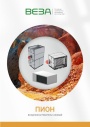
Каталог продукции Веза 2026 - Воздухонагреватели газовые ПИОН. pdf, 6.55 Mb
Каталог газовых воздухонагревателей ПИОН: назначение, конструкция и исполнения, технические характеристики, габаритные размеры, обозначение при заказе. -
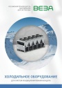
Каталог продукции Веза 2026 - Холодильное оборудование для систем кондиционирования воздуха. pdf, 4.97 Mb
Каталог холодильного оборудования Веза для систем кондиционирования: чиллеры, компрессорно-конденсаторные блоки, фанкойлы и другое оборудование — технические характеристики, габаритные размеры, обозначение при заказе. -
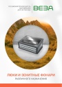
Каталог продукции Веза 2025 - Люки и зенитные фонари различного назначения. pdf, 8.45 Mb
Каталог люков дымоудаления и зенитных фонарей Веза различного назначения: конструкция и исполнения, приводы и автоматика, технические характеристики, габаритные размеры.
Новое в инструкциях
-
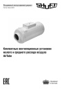
Компактные приточные установки Shuft серии AirTube. pdf, 350.53 Kb
Модели: AirTube 160, 200, 250, 315. Паспорт (объединённый эксплуатационный документ): описание устройства, монтаж, подключение электропитания, схемы электрических соединений, обслуживание, поиск и устранение неисправностей, гарантия, технические данные. -
Приточные установки Shuft серии Eco-Slim. pdf, 8.64 Mb
Модели: Eco-Slim 350, 700, 1100, 1100 W. Паспорт (объединённый эксплуатационный документ) установок с электрическим и водяным нагревателем: технические характеристики, монтаж, схема электрического подключения, обслуживание, пульт управления «Oazis», неисправности. -
Канальные фанкойлы Shuft серии SFF. pdf, 1.91 Mb
Модели: SFF-200G50 … SFF-1400G50. Инструкция по эксплуатации средненапорных канальных фанкойлов: внешние виды и размеры, технические характеристики, монтаж, электропроводка, техническое обслуживание, устранение неисправностей.