

Инструкция на Чиллеры Lennox серии HWW...
Чиллеры Lennox серии HWW – C, HWW - H, HWR. Инструкция по монтажу и эксплуатации.
Загружаем документ…
Текст инструкции
-
Water chillers and two-circuit heat pumps – water-condensing and split
type versions – HWW series HWW – C water-water chillers – cooling only HWW - H water-water chillers - heat pump version HWR motor-driven evaporative chillers with remote condenser USE and INSTALLATION MANUAL HWW-0-UM-GB-02_LENNOX Validity as of: Page 1 of 48
-
TABLE OF CONTENTS
GENERALITIES INSPECTION, CONVEYANCE, SITING Inspection Lifting and conveyance Unpacking Siting INSTALLATION Installation clearance requirements General guidelines for plumbing connections Water connection to the evaporator Instructions for the filling up of the tank Safety valve drain pipes…
-
TABLE OF CONTENTS
OPERATING LIMITS Water flow to evaporator Chilled water temperature External water temperature Operation with water at low temperatures SETTING OPERATING PARAMETERS Generalities Maximum pressure switch Minimum pressure switch Service thermostat Antifreeze thermostat Anti-recycle timer ROUTINE…
-
Dichiarazione di conformità
LA dichiarazione di conformità è allegata ad ogni macchina Declaration of conformity The declatration of conformity is attached to each unit sold. HWW-0-UM-GB-02_LENNOX Validità: 16 12 2002 Pagina 4 di 48
-
General Description
The Series The HWW series of water-condensing chillers includes a range of models capable of satisfying every need. Water-condensing units – cooling only – of [ 53.9 - 296 kW ] Heat pump reversible water-condensing units of [ 53 - 290 kW ] Motor-driven evaporative units – cooling only – of [ 46.2…
-
HWRC versions with remote condenser
o Occupies an extremely small surface area o No need to add glycol to the water in the user circuit o Possibility of installing condensers on floors with a low weight-bearing capacity, which would not be able to support the weight of a complete machine o Simplified piping, since there is no need for…
-
control kit comprising a thermostat and an auxiliary fan is available on request. The protection
rating of the unit is IP 43. NOTE: the mechanical safety devices such as the high pressure switch are of the kind that trigger directly; their efficiency will not be affected by any faults occurring in the microprocessor control circuit. in compliance with 97/23 PED. Control microprocessor: the…
-
BASIC COOLING CIRCUIT
Cooling only versions – Basic diagram of a single circuit Plate heat exchanger Scambiatore a piastre Filter dryer Filtro deidratore Sight glass Spia di flusso Scroll compressor Compressore scroll Thermostatic valve Valvola termostatica Liquid receiver Ricevitore di liquido Check valve Valvola di non…
-
Heat pump versions – Basic diagram of a single circuit
Plate heat exchanger Scambiatore a piastre Filter dryer Filtro deidratore Sight glass Spia di flusso Scroll compressor Compressore scroll Thermostatic valve Valvola termostatica Liquid receiver Ricevitore di liquido Check valve Valvola di non ritorno 4 way valve Valvola inversione di ciclo…
-
Cooling only versions with remote condenser – Diagram of a single circuit
Plate heat exchanger Scambiatore a piastre Filter dryer Filtro deidratore Sight glass Spia di flusso Scroll compressor Compressore scroll Thermostatic valve Valvola termostatica Liquid receiver Ricevitore di liquido Check valve Valvola di non ritorno 4 way valve Valvola inversione di ciclo…
-
Heat pump versions with remote condenser – Basic diagram of a single circuit
Plate heat exchanger Scambiatore a piastre Filter dryer Filtro deidratore Sight glass Spia di flusso Scroll compressor Compressore scroll Thermostatic valve Valvola termostatica Liquid receiver Ricevitore di liquido Check valve Valvola di non ritorno 4 way valve Valvola inversione di ciclo…
-
Installation
General rules - When installing or servicing the chiller, you must strictly follow the rules provided in this manual, comply with the directions on the units and take all such precautions as are necessary. - The fluids under pressure in the cooling circuit and the presence of electrical components…
-
Unpacking
The packing must be carefully removed to avoid the risk of damaging the unit. Different packing materials are used: wood, cardboard, nylon etc. It is recommended to keep them separately and deliver them to suitable waste disposal or recycling facilities in order to minimise their environmental…
-
General Guidelines for Plumbing Connections
When you are getting ready to set up the water circuit for the evaporator you should follow the directions below and in any case make sure you comply with national or local regulations (use the diagrams included in this manual as your reference). - Connect the pipes to the chiller using flexible…
-
The water circuit must be set up in such a way as to guarantee that the nominal flow rate
of the water supplied to the evaporator remains constant (+/- 15%) in all operating conditions. The compressors work intermittently, since the chilling requirements of the user generally do not coincide with the compressor output. In systems containing little water, where the thermal inertia of the…
-
A standard feature of HWW units is a device for controlling the flow rate (flow switch or
differential pressure switch) in the water circuit in the immediate vicinity of the evaporator. Any tampering with said device will immediately invalidate the warranty. It is advisable to install a metal mesh filter on the inlet water pipe. Warning: When making the plumbing connections. make sure…
-
General guidelines for Cooling connections of HWR units
HWR units are supplied pre-charged with inert nitrogen gas at a pressure of 3 bars to protect them from the penetration of humidity and are provided with threaded Rotalock weld-on connections (3 pieces) for outdoor piping. Rotalock Connection Braze-welded copper connection Piping made on site Note…
-
The following table reports the dimensions suggested for piping
Unit model Fluid line Thickness (mm) GAS line Thickness (mm) HWRC0502-0672 HWRC0742-1362 HWRC1522-2442 HWRC2582-3042 16 mm 18 mm 22 mm 28 mm 1 1 1,5 1,5 1,5 1,5 1,5 1,5 Prescriptions for laying Vertical ascending gas lines set a trap every 4 metres Vertical fluid lines: o The complete miscibility…
-
Evacuation and charging operations for HWR-type units This type of work must be carried out by qualified personnel trained to do their job in observance of current laws and regulations. 1. Introduction: The simultaneous presence of liquid and vapour makes it necessary for both to be in a state of…
-
2. Vacuum and charging machine
Tank Charging gun Cock Fig. 2 Solenoid valve Charging machine Charging piston Volumetric Flow Rate Gauge The charging piston compresses the refrigerant to a max P of 20 bar-r, thus favouring the re-condensation of any flash vapour that may have formed during transit through the line between the tank…
-
3. Vacuum cycle
In general it is preferable to apply a “long” rather than “hard” vacuum: reaching low pressures too abruptly may in fact cause any trapped humidity to evaporate instantaneously, thereby freezing part of it. Fig. 3 P [Pa] s Time The figure represents a vacuum cycle and an optimal subsequent pressure…
-
If a high % of refrigerant comes into contact with the Pirani gauge (vacuum sensor), it may “drug” the sensitive element of the latter. rendering it inefficient for a certain period of time. For this reason. if no machine for recovering refrigerant is available. it is nonetheless advisable to switch…
-
ELECTRICAL CONNECTIONS
GENERALITIES Before carrying out any job on electrical parts, make sure the power supply is disconnected. Check that the mains electricity supply is compatible with the specifications (voltage, number of phases, frequency) shown on the unit rating plate. The power connection for single-phase loads…
-
Remote controls
If you wish to include a remote control for switching the unit on and off, you must remove the bridge between the contacts indicated in the wiring diagram and connect the remote ON/OFF control to the terminals themselves [see annexed wiring diagram], then enable the "REMOTE" function by means of the…
-
The diagram above illustrates a specific property [Charles’ Law] of gases. which are more soluble in
liquids as the pressure increases but less soluble as the temperature increases: if the oil in the sump is held at a constant pressure, an increase in oil temperature will significantly reduce the amount of refrigerant dissolved in it, thus ensuring that the lubricating function desired is…
-
STARTING UP FOR THE FIRST TIME
HOW TO START UP THE Chillers OF THE HWW SERIES FOR THE FIRST TIME Water connections • Warning: the chiller is charged with HFC R407C – Group I EN 378 refrigerant (non-hazardous substances) conforming to the requirements of EEC regulation 2037/00. When making the plumbing connections, be sure to…
-
STARTING OPERATION
Before starting the unit, turn the main switch on, select the operating mode desired from the control panel and press the "ON" button on the control panel. The unit will start up if enabled: - by the safety devices of the water circulation pump/s - by the flow switch (or differential pressure…
-
- Make sure that the undercooling of the cooling fluid is limited to between 3 and 5°C. To this end
1) read the temperature indicated by a contact thermometer placed on the condenser outlet pipe; 2) read the temperature indicated on the scale of a pressure gauge connected to the liquid inlet at the condenser outlet; refer to the pressure gauge scale for the refrigerant R407C, marked with the…
-
STOPPING THE UNIT
To stop the unit press the "OFF" button on the front panel. Warning: do not stop the unit using the main switch. The latter device is used to disconnect the unit from the electricity supply when there is no passage of current, i.e. when the unit is already turned OFF. Moreover, if you completely…
-
OPERATING LIMITS
Operating limits of HWW chillers in relation to the outlet water temperature and water dew point. Applications with water T above the specified limits require the use of R134a refrigerant fluid. For details please contact the local Lennox dealer. Cooling only Units Water temperature Minimum Maximum…
-
Glycol solutions
It is possible to produce water at temperatures below 5°C and as low as -10°C using glycol solutions t hat lower the freezing point according to the following table: Minimum temperature of water produced 5 °C 2°C -1 °C -5°C Percentage of ethylene glycol (in weight) 0% 10 % 15% 25 % Freezing…
-
SETTING OPERATING PARAMETERS
GENERALITIES All the control devices are set and tested in the factory before the unit is dispatched. However, after the unit has been in service for a reasonable period of time you can perform a check on the operating and safety devices. The settings are shown in Tables II and III. All servicing of…
-
MAXIMUM PRESSURE SWITCH
The high pressure switch stops the compressor when the outlet pressure exceeds the set value. Warning: do not attempt to change the setting of the maximum pressure switch. Should the latter fail to trip in the event of a pressure increase, the pressure relief valve will open. The high pressure…
-
MAINTENANCE
The only tasks to be performed by the end user are turning the chillers on and off and switching them between the cooling and heating functions as the seasons change. All other operations are to be considered maintenance work and must thus be carried out by qualified personnel trained to do their…
-
To guarantee a constantly satisfactory performance over time, it is advisable to carry out routine
maintenance and checks as described below. Operations Frequency • Check the efficiency of all the control and safety devices Once a year • Check the terminals on the electric control board and compressor terminal boards to ensure that they are securely tightened. The movable and fixed contacts of…
-
Tightness test
Fill the circuit with anhydrous nitrogen supplied from a tank with a pressure-reducing valve until the pressure rises to 22 bars. During the pressurisation phase, do not exceed a pressure of 22 bars-r on the low pressure side The presence of any leaks must be determined using special leak detectors.…
-
Recharging with refrigerant R407C
- Connect the tank of refrigerant gas to the male 1/4 SAE inlet situated on the liquid line after discharging a little gas to eliminate air in the connection pipe. - Fill with refrigerant in liquid form until you reach 75% of the total charge. - Then connect to the inlet on the pipe between the…
-
TROUBLESHOOTING
On the next pages you will find a list of the most common causes that may cause the chilling unit to fail or malfunction. These causes are broken down according to easily identifiable symptoms. You should be extremely careful when attempting to implement any of the possible remedies suggested…
-
FAULT
Low condensation pressure. Low evaporation pressure. The compressor does not start. High evaporation pressure. HWW-0-UM-GB-02_LENNOX Possible causes Corrective actions Transducer fault. Check the setting of the condensation control device [optional]. Water T too low. Install the condensation control…
-
Performance data – cooling models HWW-C
Model HWWC055 HWWC060 HWWC070 HWWC080 HWWC090 HWWC105 HWWC115 R407C R407C R407C R407C R407C R407C R407C [kW] 53.9 59.8 68.7 81.5 89.8 103.0 121.2 [kW] 18 20.5 23.6 27.5 30.4 34.5 40.7 [kPa] 16.5 19 [kW] 12.0 14.6 15.7 18.4 22.3 25.4 30.2 Rated current absorption [A] 26.2 30.4 35.2 38.7 41.7 49.3…
-
Performance data – cooling models HWW-C
Model HWWC130 HWWC150 HWWC180 HWWC205 HWWC235 HWWC250 HWWC275 HWWC300 Refrigerant R407C R407C R407C R407C R407C R407C R407C R407C [kW] 137.3 150.7 172.9 209.6 236.7 253.9 273.5 296.1 [kW] 45.8 55.2 57.2 69.5 78.2 83.6 91.2 91.2 [kPa] [kW] 34.2 37.6 44.1 53.4 59.8 65.3 69.1 74.8 Rated current…
-
Performance data – heat pump models HWW-H
Model Refrigerant Cooling capacity (1) HWWH055 HWWH060 HWWH070 HWWH080 HWWH090 HWWH105 HWWH115 R407C R407C R407C R407C R407C R407C R407C 53 57.2 65.5 79.4 87.4 100.2 116.8 58.6 63.4 71.8 88.3 97.5 110.8 128.5 [kW] Heating capacity (2) Rated electrical input Rated current absorption Maximum current…
-
Performance data – heat pump models HWW-H
Model HWWH130 HWWH150 HWWH180 HWWH205 HWWH235 HWWH250 HWWH275 HWWH300 Refrigerant Cooling capacity (1) [kW] Heating capacity (2) R407C 134.6 R407C 147.8 R407C 169.4 R407C 205.4 R407C 231.9 R407C 248.9 R407C 268.1 R407C 290.2 148.7 163.4 187.2 227.0 256.2 274.9 296.1 320.6 Rated electrical input [kW]…
-
Performance data – models with remote condenser HWR
-
таблицы и схемы — в просмотре
-
Validità: 16 12 2002 Pagina 46 di 48
-
Validità: 16 12 2002 Pagina 47 di 48
Схемы, таблицы и рисунки — в просмотре документа выше. Клик по номеру страницы открывает её в просмотре.
Новое в каталогах
-
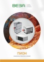
Каталог продукции Веза 2026 - Воздухонагреватели газовые ПИОН. pdf, 6.55 Mb
Каталог газовых воздухонагревателей ПИОН: назначение, конструкция и исполнения, технические характеристики, габаритные размеры, обозначение при заказе. -

Каталог продукции Веза 2026 - Холодильное оборудование для систем кондиционирования воздуха. pdf, 4.97 Mb
Каталог холодильного оборудования Веза для систем кондиционирования: чиллеры, компрессорно-конденсаторные блоки, фанкойлы и другое оборудование — технические характеристики, габаритные размеры, обозначение при заказе. -

Каталог продукции Веза 2025 - Люки и зенитные фонари различного назначения. pdf, 8.45 Mb
Каталог люков дымоудаления и зенитных фонарей Веза различного назначения: конструкция и исполнения, приводы и автоматика, технические характеристики, габаритные размеры.
Новое в инструкциях
-
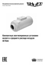
Компактные приточные установки Shuft серии AirTube. pdf, 350.53 Kb
Модели: AirTube 160, 200, 250, 315. Паспорт (объединённый эксплуатационный документ): описание устройства, монтаж, подключение электропитания, схемы электрических соединений, обслуживание, поиск и устранение неисправностей, гарантия, технические данные. -
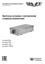
Приточные установки Shuft серии Eco-Slim. pdf, 8.64 Mb
Модели: Eco-Slim 350, 700, 1100, 1100 W. Паспорт (объединённый эксплуатационный документ) установок с электрическим и водяным нагревателем: технические характеристики, монтаж, схема электрического подключения, обслуживание, пульт управления «Oazis», неисправности. -
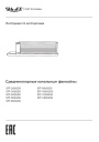
Канальные фанкойлы Shuft серии SFF. pdf, 1.91 Mb
Модели: SFF-200G50 … SFF-1400G50. Инструкция по эксплуатации средненапорных канальных фанкойлов: внешние виды и размеры, технические характеристики, монтаж, электропроводка, техническое обслуживание, устранение неисправностей.