

Инструкции на Сетевые инверторы Fronius Galvo
Сетевые инверторы Fronius Galvo 1.5-1 / 2.0-1/ 2.5-1 / 3.0-1 / 3.1-1. Оперативная инструкция.
Смотрите также: Инструкция по установке →
Загружаем документ…
Текст инструкции
-
/ Perfect Charging / Perfect Welding / Solar Energy
LEARN MORE WITH OUR HOW-TO VIDEOS www.youtube.com/FroniusSolar Operating Instructions 42,0410,1984 EN Fronius Galvo 1.5-1 / 2.0-1 2.5-1 / 3.0-1 / 3.1-1 Dummy 011-27092016 Grid-connected inverter
-
Dear reader,
Introduction Thank you for the trust you have placed in our company and congratulations on buying this high-quality Fronius product. These instructions will help you familiarise yourself with the product. Reading the instructions carefully will enable you to learn about the many different features…
-
Contents
Safety rules General Environmental conditions Qualified service engineers Noise emission values EMC measures Disposal Data protection Copyright General Device concept Proper use Warning notices on the device Controlling the inverter via Demand Response Modes (DRM) Notes for a dummy device Data…
-
General Switching the key lock on and off USB Stick as a Data Logger and for Updating Inverter Software USB stick as a datalogger Suitable USB flash drives USB stick for updating the inverter software Remove USB stick The Basic menu General Access the Basic menu Items on the Basic menu Status…
-
Safety rules
General The device is manufactured using state-of-the-art technology and according to recognised safety standards. If used incorrectly or misused, however, it can cause: injury or death to the operator or a third party, damage to the device and other material assets belonging to the operator…
-
Qualified service
engineers The servicing information contained in these operating instructions is intended only for the use of qualified service engineers. An electric shock can be fatal. Do not perform any actions other than those described in the documentation. This applies even if you are qualified to do so. All…
-
Copyright
EN Data protection The user is responsible for the safekeeping of any changes made to the factory settings. The manufacturer accepts no liability for any deleted personal settings. Copyright of these operating instructions remains with the manufacturer. The text and illustrations are all technically…
-
General
Device concept Device construction: (1) (2) (3) (1) (2) (3) (4) (5) (6) (6) (5) (4) Housing cover Inverter Wall bracket Connection area incl. DC main switch Data communication area Data communication cover The inverter transforms the direct current generated by the solar modules into alternating…
-
When designing the photovoltaic system, ensure that all of its components are operated
within their permitted operating ranges at all times. Observe all the measures recommended by the solar module manufacturer to ensure the lasting maintenance of the properties of the solar module. Obey the regulations of the energy supply company regarding feeding energy into the grid. Warning…
-
Controlling the inverter via Demand Response
Modes (DRM) IMPORTANT! To control the inverter via DRM, a Fronius DRM interface (item number 4,240,005) is required in the inverter. Installation is described in the installation instructions for the Fronius DRM interface. The installation instructions for the Fronius DRM interface are available at…
-
Data communication and Solar Net
Fronius Solar Net and data interface Fronius Solar Net was developed to make system add-ons flexible to use in a variety of different applications. Fronius Solar Net is a data network that enables multiple inverters to be linked up using system add-ons. It is a bus system that uses a ring topology.…
-
Item
Designation (2) (3) Fronius Solar Net connection / interface protocol IN Fronius Solar Net connection / interface protocol OUT 'Fronius Solar Net' / interface protocol input and output for connecting to other DATCOM components (e.g. inverter, sensor box, etc.) If several DATCOM components are linked…
-
IMPORTANT! In order to connect an S0 meter to the inverter, it may be necessary to update the inverter firmware. Pin 2 Pin 1 Pin 2 S0 + Pin 1 S0 - Requirements for the S0 meter: Must comply with the IEC62053-31 Class B standard Max. voltage 15 V DC Max. current when ON 15 mA Min. current when ON 2…
-
After cutting out because of overcurrent or undervoltage, the inverter attempts to restore
the power supply in the Fronius Solar Net every 5 seconds while the fault is still present. Once the fault is rectified, power to the Fronius Solar Net will be restored within 5 seconds. Example Recording and archiving data from the inverter and sensor using a Fronius Datamanager and a Fronius…
-
System monitoring
General Where no special device model is present, the inverter is fitted with WLAN-compatible Fronius Datamanager 2.0 system monitoring as standard. Among other things, system monitoring includes the following functions: Own web page displaying current data and a wide range of different setting…
-
NOTE! If the photovoltaic system has only one inverter, steps 1 and 2 below can
be skipped. In this case, starting for the first time will commence with step 3. 1 Connect inverter with Fronius Datamanager 2.0 or Fronius Datamanager Box 2.0 to the Fronius Solar Net 2 When networking several inverters together in Fronius Solar Net: Set the Fronius Solar Net master / slave switch…
-
The technician wizard is intended for the installer and contains standard-specific settings
Running the technician wizard is optional. If the technician wizard is run, it is vital to note the service password that is issued. This service password is necessary for setting the EVU Editor menu item. If the technician wizard is not run, no specifications regarding power reduction are set.…
-
Controls and indicators
Controls and indicators (1) (2) (3) (4) (5) (6) (7) (8) Item Description (1) Display showing values, settings and menus Monitoring and status LEDs (2) General status LED (red) on steady, if a status message is being displayed on the monitor if the process of feeding energy into the grid is…
-
The keys are capacitive, and any exposure to water can impair their function. Wipe the
keys dry with a cloth if necessary to ensure optimum functionality. Display Power for the display comes from the mains voltage. Depending on the setting selected in the Setup menu, the display can be kept on all day. IMPORTANT! The display on the inverter is not a calibrated measuring device. A…
-
The menu level
Activate display backlighting 1 Press any key The display backlighting is activated. There is an option under 'Display Settings' in the SETUP menu to set the display backlighting so that it is on all the time or off all the time. Automatic deactivation of display backlighting / choose 'NOW' menu…
-
The NOW, LOG and GRAPH menu items
NOW LOG GRAPH NOW (Displays real-time values) GRAPH GRAPH LOG (Data recorded today, during the current calendar year and since the inverter was first commissioned) GRAPH Day characteristic displays a plot showing the power output during the day. The time axis is scaled automatically. Press the…
-
Values displayed in the LOG menu item
(for today, during the current calendar year and since the inverter was started for the first time) AC Energy Yield (kWh / MWh) Energy fed into the grid during the period in question There may be discrepancies with values displayed on other measuring instruments because of differences in measuring…
-
SETUP menu item
Initial setting The inverter is pre-configured and ready to use. There is no need to enter any initial settings before using it to feed energy into the grid, as this is a fully-automated process. The SETUP menu item allows the initial settings of the inverter to be changed easily to bring it in…
-
Exiting an entry
GRAPH 4 To exit a menu entry, press the 'Back' key The menu level appears If no key is pressed for 2 minutes, The inverter switches from wherever it is on the menu level back to the 'NOW' display mode (exception: 'Standby' Setup menu entry), the display backlighting goes out. The amount of energy…
-
Select 'Time / Date' from the Setup menu 2 Press the 'Enter' key EN Application example: Setting the time An overview of the values that can be changed is displayed. 3 Use the 'Up' or 'Down' keys to select 'Set time' 4 Press the 'Enter' key The current time appears. (HH:MM:SS, 24-hour clock), the…
-
The Setup menu items
Standby Manual activation / deactivation of Standby mode - No energy is fed into the grid. The Startup LED will show steady orange. In Standby mode, no other menu item at menu level can be accessed or adjusted. The automatic switchover into the 'NOW' display mode after 2 minutes of keyboard…
-
WiFi Access Point [not available] Displayed if there is no system monitoring present on the inverter. DATCOM Checking data communications, entering the inverter number, DATCOM night mode, protocol settings Setting range Status / inverter number / protocol type Status Indicates data communication is…
-
NOTE! To successfully update the inverter software, the USB stick provided for
the purpose must not have a hidden partition or any encryption (see chapter "Suitable USB sticks"). 2 Save the update file to the highest data level of the USB stick 3 Open the data communication area 4 Plug the USB stick containing the update file into the USB socket in the data communication area…
-
Activate relay, relay settings, relay test
Setting range EN Relays Relay mode / Relay test / Switch-on point* / Switch-off point* * these are only shown if the 'E-Manager' function has been activated under 'Relay mode'. Relay mode for selecting the different functions of the floating switch contact in the data communication area: Alarm…
-
To activate the 'Energy-Manager' function, select 'E-Manager' and press the 'Enter' key
When the 'Energy-Manager' function is running, the 'Energy-Manager' symbol will appear in the top left corner of the display: when the floating NO contact is off (open contact) when the floating NO contact is on (closed contact) To deactivate the 'Energy-Manager' function, select a different…
-
Summer/winter time
Activate/deactivate automatic changeover between summer and winter time IMPORTANT! Only use the automatic summer/winter time changeover function if the Fronius Solar Net ring does not include any LAN- or WLAN-compatible system components (e.g. Fronius Datalogger Web, Fronius Datamanager or Fronius…
-
Illumination
Initial setting for display illumination The "Illumination" menu item only relates to the display backlighting. Energy yield Setting range AUTO / ON / OFF Factory setting AUTO AUTO: The display backlighting is activated by pressing any key. If no key is pressed for 2 minutes, the display…
-
The INFO menu item
INFO Measured values PSS status Grid status INFO (Information about the device and the software) Measured values Display range: PV ins. / Ext. lim. / U PV1 / GVDPR / Fan #1 PV Iso. Insulation resistance of the PV system (with ungrounded solar modules and solar modules with negative pole grounding)…
-
Device information
For displaying the settings that will be of relevance to an energy supply company. The values shown will depend on the country setup or the device-specific settings of the inverter. Display range General / Country-specific setting / MPP tracker / Grid monitoring / Grid voltage limits / Grid…
-
Status
ON / OFF voltage-dependent power reduction EN AC voltage derating: GVDPRe Threshold from which the voltage-dependent power reduction begins GVDPRv Reduction gradient used to reduce the power, e.g.: 10% per volt above the GVDPRe threshold. Message Activates the dispatch of an info message via Fronius…
-
Switching the key lock on and off
General The inverter has a key lock function. When the key lock is active, the Setup menu is not accessible, i.e. the setup data cannot be changed accidentally (or maliciously). The code 12321 has to be entered in order to activate / deactivate the key lock. Switching the key lock on and off 1 Press…
-
USB stick as a datalogger
If a USB stick is connected to the USB A socket it can function as a datalogger for an inverter. At any time, the logging data stored on the USB stick can be imported into the Fronius Solar.access software using the FLD file that was logged at the same time, viewed directly in third-party programs…
-
USB symbol on the inverter display, e.g. in display mode 'NOW'
If the inverter detects a USB flash drive, the USB symbol will appear in the top right corner of the display. When inserting a USB flash drive, check whether the USB symbol is displayed (it may also flash). NOW AC Output Power NOTE! Please note for outdoor applications that conventional USB flash…
-
The Basic menu
General The Basic menu is used to set the following parameters, which are important for installing and operating the inverter: - DC operating mode Fixed voltage MPPT1 initial voltage USB logbook Access the Basic menu - Insulation settings TOTAL reset Event counter 1 Press the 'Menu' key The menu…
-
Items on the Basic menu
The Basic menu contains the following items: MPP Tracker 1 - DC operating mode: MPP AUTO FIX MPP USER - Fixed voltage: for inputting a fixed voltage, 120 - 440 V - MPPT1 initial voltage: for inputting the MPPT1 initial voltage, 120 - 440 V USB log book Activates or deactivates the function for…
-
Insulation fault
for activating and deactivating insulation monitoring, with error message and immediate shutdown of the inverter if there is an insulation fault ON / OFF (depends on the country setup) - Threshold error: for setting an insulation threshold at which the inverter produces an error message and…
-
Status diagnostics and troubleshooting
Displaying status codes The inverter performs a system self diagnosis that automatically detects many faults that may occur and shows them on the display. This means you are promptly made aware of malfunctions in the inverter and the photovoltaic system, or of any installation or operating faults.…
-
Class 3 includes status codes that may occur while feeding energy into the grid, but generally do not cause the process to be interrupted for any length of time. The inverter disconnects automatically from the grid, the grid is then monitored as specified and the inverter attempts to resume feeding…
-
Code
Description Behaviour Remedy 412 Fixed voltage mode has been selected instead of MPP voltage mode and the fixed voltage has been set to too low or too high a value. - If this status code keeps recurring, contact your system engineer 415 Safety cut-out via option card or RECERBO has triggered The…
-
Class 5 status codes do not generally prevent the feeding of energy into the grid, but can
restrict it. These status code are displayed until they are acknowledged by pressing a key (the inverter, however, continues to operate normally in the background). Code Description Behaviour Remedy 502 Insulation error on the solar modules Warning message is shown on the display If this status code…
-
Class 6 status
codes Code 668 Some of the class 6 status codes necessitate intervention by a Fronius-trained service engineer. Description Behaviour Remedy Incorrect input signal on the multifunction current interface The inverter is not feeding any energy into the grid. The status code is displayed in the case of…
-
Behaviour
Remedy Warning message is shown on the display Check USB stick and the data contained on it or replace USB stick Never unplug a USB stick if the 'Data Transmission' LED is still flashing or lit. If the status code is displayed all the time: notify a Froniustrained service engineer Warning message is…
-
Technical data
Fronius Galvo 1.5-1 Input data MPP voltage range 120 - 335 V DC Max. input voltage (at 1000 W/m²/ -10 °C in an open circuit) 420 V DC Max. input current 13.3 A Max. short circuit current of the solar modules 20.0 A Max. feedback current4) 8.9 A Output data Nominal output power (Pnom) 1500 W Max.…
-
Input data
EN Fronius Galvo 2.0-1 MPP voltage range 120 - 335 V DC Max. input voltage (at 1000 W/m²/ -10 °C in an open circuit) 420 V DC Max. input current 17.8 A Max. short circuit current of the solar modules 26.8 A Max. feedback current4) 11.9 A Output data Nominal output power (Pnom) 2000 W Max. output…
-
Input data MPP voltage range 165 - 440 V DC Max. input voltage (at 1000 W/m²/ -10 °C in an open circuit) 550 V DC Max. input current 16.6 A Max. short circuit current of the solar modules 24.8 A Max. feedback current4) 11 A Output data Nominal output power (Pnom) 2500 W Max. output power 2500 W…
-
Input data
EN Fronius Galvo 3.0-1 MPP voltage range 165 - 440 V DC Max. input voltage (at 1000 W/m²/ -10 °C in an open circuit) 550 V DC Max. input current 19.8 A Max. short circuit current of the solar modules 29.6 A Max. feedback current4) 13.2 A Output data Nominal output power (Pnom) 3000 W Max. output…
-
Input data MPP voltage range 165 - 440 V DC Max. input voltage (at 1000 W/m²/ -10 °C in an open circuit) 550 V DC Max. input current 20.7 A Max. short circuit current of the solar modules 31.0 A Max. feedback current4) 13.8 A Output data Nominal output power (Pnom) 3100 W Max. output power 3100 W…
-
Nominal grid voltage
1 ~ NPE 230 V Grid voltage tolerance +10 / -5 % 1) Nominal frequency 50 - 60 Hz 1) Degree of protection IP 65 Dimensions h x w x d 645 x 431 x 204 mm Weight Explanation of footnotes 1) 2) 3) 4) 5) 6) 7) Applicable standards and guidelines 16.75 kg The values quoted are default values; the inverter…
-
Warranty terms and conditions, and disposal
Fronius manufacturer's warranty Detailed, country-specific warranty terms are available on the internet: www.fronius.com/solar/warranty To obtain the full warranty period for your newly installed Fronius inverter or storage system, please register at: www.solarweb.com. Disposal 56 If you decide in…
Схемы, таблицы и рисунки — в просмотре документа выше. Клик по номеру страницы открывает её в просмотре.
Новое в каталогах
-
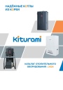
Каталог отопительного оборудования Kiturami 2024. pdf, 8.78 Mb
Каталог настенных газовых котлов World Alpha, напольных газовых TGB HiFin, STSG 47, KSG, дизельных Turbo, KSO, пеллетных KRP и твердотопливных KF: технические характеристики, пульты управления, дымоходы, справочная информация. -
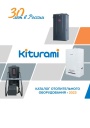
Каталог отопительного оборудования Kiturami 2023. pdf, 8.65 Mb
Каталог настенных газовых котлов World Alpha, напольных газовых TGB HiFin, STSG 47, KSG, дизельных Turbo, KSO, пеллетных KRP и твердотопливных KF: технические характеристики, пульты управления, дымоходы, справочная информация. -
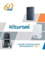
Каталог отопительного оборудования Kiturami 2022. pdf, 7.65 Mb
Каталог настенных газовых котлов World Alpha, напольных газовых STSG, TGB HiFin, KSG, дизельных STSO, Turbo, KSO, пеллетных KRP, комбинированных KRH, KRM и твердотопливных KF: технические характеристики.
Новое в инструкциях
-

Клапан приоритета бойлера ГВС ZOTA BSR. Паспорт и инструкция по эксплуатации. pdf, 208.58 Kb
Паспорт и инструкция по эксплуатации трёхходового клапана приоритета бойлера ГВС BSR (ZOTA): технические характеристики, монтаж, подключение к системе отопления, электрические схемы, ввод в эксплуатацию и эксплуатация, настройка, техническое обслуживание, неисправности и методы их устранения, гарантийные обязательства. -
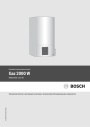
Настенный газовый котел Bosch Gaz 2000 W WBN2000-24C RN. Технический паспорт, инструкция по монтажу и техническому обслуживанию. pdf, 5.08 Mb
Технический паспорт и инструкция по монтажу и техническому обслуживанию для специалистов газового котла Bosch Gaz 2000 W: комплект поставки, размеры, отвод дымовых газов, монтаж и электроподключение, ввод в эксплуатацию, сервисные функции, неисправности. -
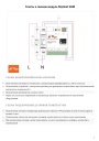
Контроллер Эван MyHeat Smart (MyHeat GSM). Схемы подключения и настройка. pdf, 1.29 Mb
Руководство по подключению контроллера MyHeat Smart (модуль MyHeat GSM): схемы подключения блока питания, датчиков температуры, котла, насосов и трёхходового клапана, настройка датчиков, сигналов тревоги и инженерного оборудования в web-интерфейсе.