

Инструкция на Настенные сплит-системы Toshiba серии RAS .... (сервис-мануалы)
Настенные сплит-системы Toshiba серии RAS-07SKSX / RAS-07S2AX, RAS-09SKSX / RAS-09S2AX. Инструкция по обслуживанию и ремонту.
Смотрите также: Инструкция по обслуживанию и ремонту →
Загружаем документ…
Текст инструкции
-
SERVICE MANUAL
AIR CONDITIONER SPLIT WALL TYPE RAS-07SKSX / RAS-07S2AX RAS-09SKSX / RAS-09SASX Revised May, 2007
-
CONTENTS
1. SPECIFICATIONS 2. CONSTRUCTION VIEWS 2-1 Indoor Unit 2-2 Outdoor Unit (RAS-07S2AX) 2-3 Outdoor Unit (RAS-09SASX) 3. WIRING DIAGRAM 4. SPECIFICATION OF ELECTRICAL PARTS 4-1 Indoor Unit 4-2 Outdoor Unit (RAS-07S2AX) 4-3 Outdoor Unit (RAS-09SASX) 5. REFRIGERATION CYCLE DIAGRAM 5-1 RAS-07GKSX /…
-
10. PARTS REPLACEMENT
10-1 Indoor Unit 10-2 Outdoor Unit (RAS-07S2SX) 10-3 Outdoor Unit (RAS-09SASX) 11. EXPLODED VIEWS AND PARTS LIST 11-1 Indoor Unit (E-Parts Assy) 11-2 Indoor Unit 11-3 Outdoor Unit (RAS-07S2SX) 11-4 Outdoor Unit (RAS-09SASX) −2−
-
1. SPECIFICATIONS
MODE L RA S-09SKSX / RA S-09SASX RA S-07SKSX / RA S-07S2AX Cooling IT E M Capacity kW 220V 240V 2.00 2.00 Phase Power source 220V 240V 2.50 2.50 1 V 220 - 240 Hz 50 Power consumption kW 0.62 0.66 0.84 0.88 Power factor % 2.72 2.72 Running Indoor A current Outdoor A Starting current A Moisture…
-
Note : 1
• Capacity is based on the following temperature conditions. Temperature Indoor unit inlet air temperature Outdoor unit inlet air temperature Condition JIS C9612 (DB) 27°C (WB) 19°C (DB) 35°C (WB) 24°C Note : 2 *1 No need to charge extra refrigerant. −4− Cooling
-
2. CONSTRUCTION VIEWS
135 2-1. Indoor Unit 54 16 Wireless remote control –5–
-
2-2. Outdoor Unit
CL CL −6 −
-
3. WIRING DIAGRAM
CN04 P04 R22 VARISTOR SG01 DSA BRW DC5V 3 GRN & YEL T6.3A 250VAC CN31 RY01 R21 VARISTOR BLU 4 BLK BLK BLK BLK BLK CN01 1 2 HEAT EXCHANGER 1 2 SENSOR (TC) GRN&YEL WHI BLK INDOOR OUTDOOR OUTDOOR TERMINAL BLOCK 1(L) 2(N) CHASSIS RED BLK CAPACITOR RED BLK CAPACITOR FAN MOTOR RED WHI OVERLOAD RELAY BLK…
-
4. SPECIFICATION OF ELECTRICAL PARTS
-
4-3. Outdoor Unit (RAS-09SASX)
-
5. REFRIGERATION CYCLE DIAGRAM
5-1. RAS-07SKSX / RAS-07S2AX Indoor unit Heat exchanger Cooling 0.39m (Connecting pipe) ∅9.52 T1 0.49m (Connecting pipe) ∅6.35 Cross flow fan O.D.:9.52mm O.D.:6.35mm P Packed valve (∅9.52) Packed valve (∅6.35) Cooling Cooling Compressor PH108X1C-4DZDN2 Capillary tube ∅1.2x500s Heat exchanger Cooling…
-
5-2. RAS-09SKSX / RAS-09SASX
Indoor unit Heat exchanger Cooling 0.39m (Connecting pipe) ∅9.52 T1 0.49m (Connecting pipe) ∅6.35 Cross flow fan O.D.:9.52mm O.D.:6.35mm P Packed valve (∅9.52) Packed valve (∅6.35) Cooling Cooling Compressor QK164PBA Capillary tube ∅1.5x700s Heat exchanger Cooling Mark ( ) means check points of Gas…
-
6. CONTROL BLOCK DIAGRAM
Main Unit Control Panel Heat Exchange sensor M.C.U. Operation Display Functions • Louver Control Thermo. Sensor Timer Display • 3-minutes Delay at Restart for Compressor Infrared Rays Signal Reciver Initiallizing Circuit Clock Frequency Oscillator Circuit Power Supply Circuit Noise Filter • Motor…
-
7. OPERATION DESCRIPTION
7-1. Remote control 1 7-1-1. Function of Push Putton 1 Infrared signal emitter 2 Set louver button (FIX) 3 Auto Louver button (SWING) MODE AUTO COOL 4 Mode select button (MODE) TEMP. AUTO QUIET B DRY AUTO FAN 5 Reset button (RST) FAN Hr.ON 6 On timer button (ON) OFF TEMP. 14 7 Off timer button (OFF)…
-
7-1-2. Display of Remote Control
All indications, except for the clock time indicator, are displayed by pressing the 1. Transmission mark button. 6. Swing Indicate when louver is swing. Press swing button to start the swing operation and press it again to stop the swing operation. This transmission mark indicates when the remote…
-
7-2. Outline of Air Conditioner Control
This is a fixed capacity type air conditioner, which uses a AC motor for an indoor fan. The AC motor drive circuit is mounted in the indoor unit. And electrical parts which operate the compressor and the outdoor fan motor, are mounted in the outdoor unit. The air conditioner is mainly controlled by…
-
7-3-1. Fan only operation
([MODE] button on the remote control is set to the fan only operation.) (1) When [FAN] button is set to AUTO, the indoor fan motor operates as shown in Fig. 7-3-1. When [FAN] button is set to LOW, MED, or HIGH, the motor operates with a constant air flow. Preset temp. ON ON 0.5 OFF OFF ON 0 (Room…
-
7-3-3. Dry operation
([MODE] button on the remote control is set to the dry operation.) (1) One of 2 operations (Cooling or Fan only) is selected according to difference between the preset temperature and the room temperature at which the automatic operation has started, as shown in Fig. 7-3-6. The Fan only operation…
-
7-5. Auto Restart Function
This indoor unit is equipped with an automatic restarting function which allows the unit to restart operating with the set operating conditions in the event of a power supply being accidentally shut down. The operation will resume without warning three minutes after power is restored. This function…
-
7-5-2. How to Cancel the Auto Restart Function
To cancel auto restart function, proceed as follows : Repeat the setting procedure : the unit receives the signal and beeps three times. The unit will be required to be turned on with the remote controller after the main power supply is turned off. • When the system is on stand-by (not operating)…
-
8. INSTALLATION PROCEDURE
8-1. Safety Cautions For general public use Power supply cord of parts of appliance for Outdoor use shall be at least polychloroprene sheathed flexible cord (design H07 RN-F), or cord designation 245 IEC66.(Shall be installed in accordance with national wiring regulations.) CAUTION To Disconnect the…
-
REQUIREMENT OF REPORT TO THE LOCAL POWER SUPPLIER
Please make absolutely sure that the installation of this appliance is reported to the local power supplier before installation. If you experience any problems, or if the installation is not accepted by the supplier, the service agency will take adequate countermeasures. Remark per EMC Directive…
-
mm or m 47 mm or more 8-2. Installation Diagram of Indoor and Outdoor Units ore For the rear left and left piping Hook 1 Installation Wall plate Hoo Air (At tac h to filte k 120 mm or m ore Do not allow the drain hose to get slack. r the fron t pa nel .) Cut the piping hole sloped slightly. Shield…
-
8-3. Installation
8-3-1. Optional installation parts Part Code Parts name Q'ty A Refrigerant piping Liquid side : ∅6.35 mm Gas side : ∅ 9.52 mm One each B Pipe insulating material (polyethylene foam, 6 mm thick) C Putty, PVC tapes 1 One each <Fixing bolt arrangement of outdoor unit> 500 mm Air inlet 53 mm 280 mm 97…
-
8-3-2. Accessory and installation parts
Part No. Part name (Q'ty) 1 Part No. Part name (Q'ty) 2 Active Carbon-Catechin filter x 2 Battery x 2 4 Wireless remote control x 1 Others Part name (Q'ty) 5 3 Installation plate x 1 Part No. 6 Mounting screw ∅ 4 x 25 l x 6 Remote control holder x 1 Name Owner’s manual 7 Installation manual Pan head…
-
8-4-2. Cutting a hole and mounting installation
plate 8-4. Indoor Unit 8-4-1. Installation place • A place which provides the spaces around the indoor unit as shown in the above diagram. • A place where there is no obstacle near the air inlet and outlet. • A place that allows easy installation of the piping to the outdoor unit. • A place which…
-
<When the installation plate is directly mounted on
the wall> 1. Securely fit the installation plate onto the wall by screwing it in the upper and lower parts to hook up the indoor unit. 2. To mount the installation plate on a concrete wall with anchor bolts, utilize the anchor bolt holes as illustrated in the above figure. 3. Install the…
-
<How to connect the connecting cable>
Wiring of the connecting cable can be carried out without removing the front panel. Cord clamp Terminal block 1. Remove the air inlet grille. Open the air inlet grille upward and pull it toward you. 2. Remove the terminal cover and cord clamp. 3. Insert the connecting cable (according to the local…
-
8-4-4. Piping and drain hose installation
How to fix the drains cap 1) Insert hexagonal wrench (4 mm) in a center head. <Piping and drain hose forming> * Since dewing results in a machine trouble, make sure to insulate both the connecting pipes. (Use polyethylene foam as insulating material.) 4 mm Left Bottom right Right Piping preparation…
-
<Left-hand connection with piping>
8-4-5. Indoor unit fixing Bend the connecting pipe so that it is laid within 43 mm 1. Pass the pipe through the hole in the wall, and hook above the wall surface. If the connecting pipe is laid the indoor unit on the installation plate at the upper exceeding 43 mm above the wall surface, the indoor…
-
8-4-6. Drainage
8-5. Outdoor Unit 1. Run the drain hose sloped downwards. 8-5-1. Installation place NOTE • Hole should be made at a slight downward slant on the outdoor side. Do not form the drain hose into a wavy shape. Do not rise the drain hose. 50 mm or more Do not put the drain hose end in the drainage ditch.…
-
(Unit : N·m)
8-5-2. Refrigerant piping connection 1. Cut the pipe with a pipe cutter. Roughness Obliquity 90° Warp Fig. 8-5-2 Outer dia. of copper pipe Tightening torque ∅6.35 16 to 18 (1.6 to 1.8 kgf·m) ∅9.52 30 to 42 (3.0 to 4.2 kgf·m) • Tightening torque of flare pipe connections 2. Insert a flare nut into…
-
8-5-3. Evacuating
<Packed valve handling precautions> After the piping has been connected to the indoor unit, you can perform the air purge together at once. • Open the valve stem all the way out; but do not try to open it beyond the stopper. • Securely tighten the valve stem cap with torque in the following table…
-
8-5-4. Wiring connection
1. Remove the valve cover from the outdoor unit. 2. Connect the connecting cable to the terminal as identified with their respective matched numbers on the terminal block of indoor and outdoor unit. 3. When connecting the connecting cable to the outdoor unit terminal, make a loop as shown in the…
-
2. Set the remote control selector switch with the
remote control 8-7. Others 8-7-1. Gas leak test [B] is indicated on the liquid crystal display when setting remote control selector switch to B. [A] is not indicated on the display even if the selector switch is set to A. Valve cover 1) Load the remote control with the batteries. 2) Press the…
-
9. TROUBLESHOOTING CHART
9-1. Troubleshooting Procedure Follow the details of 9-2. Basic Check Items. If there is no troub le corresponding to 9-2, check whether or not there are faulty parts following 9-4. Self-Diagnosis by Remote Control. 9-2. Basic Check Items 9-2-1. Power supply voltage The line voltage must be AC 220 −…
-
9-3. Primary Judgement
9-3-2. Failure diagnosis 9-3-1. Role of indoor unit controller The indoor unit controller receives the operation commands from the remote control and executes them. • Temperature measurement at the air outlet of the indoor heat exchanger by the indoor temperature sensor • Temperature setting of the…
-
9-4. Self-Diagnosis by Remote Control
(Check Code) (1) If the lamps are indicated as shown B to G in Table 9-3-1, exchanger the self-diagnosis by the remote control. (2) When the remote control is set to the service mode, the indoor controller diagnoses the operation condition and indicate the information of the self-diagnosis on the…
-
Table 9-4-1
Block level Check code Block Indoor P.C. board Diagnosis function Check code Air Conditioner status Symptom Condition Judgement and action Thermo. sensor short/break. Continued operation. Indicated when detected abnormal 1.Check thermo sensor. 2.If it is OK, check P.C. board. Heat exchanger sensor…
-
9-5. Troubleshootig Flowcharts
9-5-1. Power can not be turned on (No operation at all) <Preliminary checks> Operation (1) Is the supply voltage normal? (2) Is the connection to the AC output OK.? Check Items Cooling Model Main cause Shut off the power supply from AC outlet once and turn it on after 5 seconds. Countermeasure…
-
9-5-2. Power can not be turned on after replacing indoor P.C. board
<Checking Procedure> Connect the AC Power supply Does the OPERATION lamp blink? NO Is it wired as shown in Figure below? YES Return the wiring of the power relay is returned to the normal procedure. NO YES To the paragraph of "No Power turns on". Black White 1 2 Indoor Terminal Block CN31 Brown Blue…
-
9-5-3. Outdoor unit does not operate
Shut off the power supply from AC outlet once and turn it on after 5 seconds. Does the OPERATION lamp blink? NO See "Power can not be turned on". YES Does the power turn on by pushing the [START/STOP] button of the remote control? NO See "Power can not be turned on". YES Is AC 220-240V supplied…
-
9-5-4. Only compressor does not operate
Shut off the power supply from AC outlet once and turn it on after 5 seconds. Does the OPERATION lamp blink? NO See "Power can not be turned on". YES Does the power turn on by pushing the [START/STOP] button of the remote control? NO See "Power can not be turned on". YES Is the voltage across the…
-
9-5-5. Only outdoor fan does not operate
Shut off the power supply from AC outlet once and turn it on after 5 seconds. Does the OPERATION lamp blink? NO See "Power can not be turned on". YES Does the power turn on by pushing the [START/STOP] button of the remote control? NO See "Power can not be turned on". YES Is the voltage across the…
-
Cooling Model
Shut off the power supply once. Turn the power supply. Does the fan stop in no operating status? NO Replace the P.C. board. Control P.C. board is defective. YES Start the operation with low fan setting in cool operation. Does the fan rotate? NO YES Does AC 120V or higher voltage apply to between red…
-
9-6. Troubleshooting for Remote Control (Including the Indoor P.C. Board)
There is no been from the indoor unit. The operation lamp of the air conditioner main unit does not light. Push the [START / STOP] button. Does the transmission indicator blink? NO YES Is there direct sunlight on the receptor of the air conditioner? Reset the remote control by use the tip pencil…
-
(2) Inspection procedres
1) When a P.C. board is judged to be defective, (1) Operating precautions check for disconnection, burning, or discolora1) When removing the front panel or the P.C. board, tion of the copper foil pattern or this P.C. board. be sure to shut off the power supply. 2) The P.C. board consists of the…
-
(3) Checking procedure
Cooling Model Table 9-6-1 No. Procedure Check Point (Symptom) Causes 1 Shut off the power supply and remove the P.C. board assembly from the electronic parts base. Remove the connecting cable from the terminal block. 1. Is the fuse blown? 1. • Application of shock voltage. • Overload by…
-
Table 9-6-3 Approximate resistance value of thermo sensor
(kΩ) Temperature 0°C 10°C 20°C 25°C 30°C Resistance value 33.8 20.35 12.59 10.00 7.99 9-6-3. How to shorten time of restart delay timer 1 2 Press [CLR] button while pressing [CHK] button with a tip of a pencil. Then press [START/STOP] signal to the indoor unit. MODE AUTO COOL TEMP. FAN AUTO QUIET…
-
10. PART REPLACEMENT
10-1. Indoor Unit No. 1 Part name Front panel Procedures How to remove the front panel 1) Stop the operation of the air conditioner and turn off its main power supply. 2) Pull the air inlet grille toward you to open it and remove the air inlet grille. Then remove the 2 screws fixing the front panel.…
-
Part name
Procedures 4 Heat exchanger 1) Remove the front panel, electrical part and the horizontal louver following procedure 3. 2) Remove the pipe holder at the rear side of main unit. 3) Remove the 2 screws on the heat exchanger at the base bearing. 4) Remove the screw on the heat exchanger at the fixed…
-
10-2. Outdoor Unit (RAS-07S2AX, RAS-09SASX)
No. 1 Part name Common procedure Procedures 1. Detachment 1) Stop operation of the air conditioner, and turn off the main switch and breaker of the air conditioner. 2) Remove the valve cover. (ST1T∅4 x 10s 1 pc) • After removing screw, remove the valve cover pulling it downward. 3) Remove the wiring…
-
Fan motor 1) Perform work of item 1 of 1 and 1 of 2. 2) Remove the flange nut fixing the fan motor and the propeller fan. • Flange nut is loosened by turning clockwise. (To tighten the flange nut, turn counterclockwise.) 3) Remove the propeller fan. 4) Disconnect the connector for the fan motor from…
-
Part name Fan guard Procedures Remarks 1. Detachment 1) Perform work of item 1 of 1 and 1 of 2. Requirement: Perform the work on a corrugated cardboard, cloth, etc. to prevent scratches to the product. 2) Remove the front cabinet, and place it down so that the fan guard side faces downwards. 3)…
-
11. EXPLODED VIEWS AND PARTS LIST
11-1. Indoor Unit (E-Parts Assy) Location No. Part No. 43T60378 43T69371 43T69005 43T69612 43T69364 Description 406 414 Location No. Part No. 43T62003 43T69622 43T69623 43T60343 TERMINAL SENSOR;HEAT EXCHANGER SENSOR;THERMOSTAT PC BOARD ASSY ;WRS-LED FUSE,TEMPERATURE − 54 − Description CORD CLAMP…
-
11-2. Indoor Unit
Location No. Part No. 43T00462 43T09393 43T03358 43T80315 43T09392 43T70313 43T79301 43T21363 43T44379 43T47353 43T47355 43T11317 43T19333 43T49329 Description Location No. Part No. Description 43T49006 43T22312 43T39319 43T20323 43T39320 43T39321 43T21393 43T82309 43T69437 43T63002 43T62326…
-
11-3. Outdoor Unit (RAS-07S2AX)
8,10 7,9 Location No. Part No. 43T42335 43T41365 43T49327 43T97001 43T43407 43T00448 43T46308 43T00347 43T47331 43T47332 43T47007 43T00486 43T21341 43T20324 43T47001 Description Location No. Part No. Description 43T19335 43T04304 43T39326 43T39325 43T19337 43T00481 43T96305 43T62323 43T19336…
-
11-4. Outdoor Unit (RAS-09SASX)
CAPILLARY TUBE Location No. Part No. 43T42335 43T41390 43T49327 43T97001 43T43406 43T00448 43T46308 43T00347 43T47331 43T47332 43T47008 43T00487 43T21341 43T20324 43T47001 Description Location No. Part No. Description 43T19335 43T04304 43T39326 43T39325 43T19337 43T00481 43T96305 43T62323 43T19336…
-
FILE NO. SVM-03001(1)
TOSHIBA CARRIER (THAILAND) CO.,LTD. 144/9 MOO 5, BANGKADI INDUSTRIAL PARK, TIVANON ROAD, TAMBOL BANGKADI, AMPHUR MUANG, PATHUMTHANI 12000,THAILAND. – 72 –
Схемы, таблицы и рисунки — в просмотре документа выше. Клик по номеру страницы открывает её в просмотре.
Новое в каталогах
-
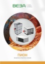
Каталог продукции Веза 2026 - Воздухонагреватели газовые ПИОН. pdf, 6.55 Mb
Каталог газовых воздухонагревателей ПИОН: назначение, конструкция и исполнения, технические характеристики, габаритные размеры, обозначение при заказе. -
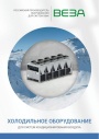
Каталог продукции Веза 2026 - Холодильное оборудование для систем кондиционирования воздуха. pdf, 4.97 Mb
Каталог холодильного оборудования Веза для систем кондиционирования: чиллеры, компрессорно-конденсаторные блоки, фанкойлы и другое оборудование — технические характеристики, габаритные размеры, обозначение при заказе. -
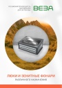
Каталог продукции Веза 2025 - Люки и зенитные фонари различного назначения. pdf, 8.45 Mb
Каталог люков дымоудаления и зенитных фонарей Веза различного назначения: конструкция и исполнения, приводы и автоматика, технические характеристики, габаритные размеры.
Новое в инструкциях
-
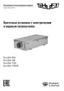
Приточные установки Shuft серии Eco-Slim. pdf, 8.64 Mb
Модели: Eco-Slim 350, 700, 1100, 1100 W. Паспорт (объединённый эксплуатационный документ) установок с электрическим и водяным нагревателем: технические характеристики, монтаж, схема электрического подключения, обслуживание, пульт управления «Oazis», неисправности. -
Канальные фанкойлы Shuft серии SFF. pdf, 1.91 Mb
Модели: SFF-200G50 … SFF-1400G50. Инструкция по эксплуатации средненапорных канальных фанкойлов: внешние виды и размеры, технические характеристики, монтаж, электропроводка, техническое обслуживание, устранение неисправностей. -
Модульные чиллеры с воздушным охлаждением конденсатора Electrolux серии EMACO. pdf, 10.13 Mb
Модели: EMACO-220.V2, EMACO-440.V2. Инструкция по эксплуатации чиллера с воздушным охлаждением конденсатора (модульного блока системы кондиционирования): меры безопасности, технические и эксплуатационные требования, принцип работы, технические характеристики, подъём блока, схема соединения нескольких модулей, вспомогательный электронагреватель, электрическая схема, регулировка и пуск, техническое обслуживание, поиск и устранение неисправностей, инструкция к пульту управления, коды аварийных сигналов, схема подключения внешнего насоса.